1
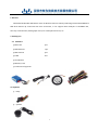
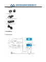
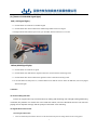
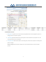
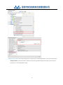
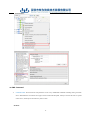
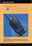
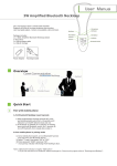
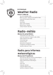
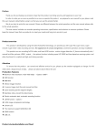
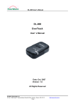
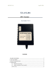
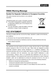
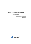
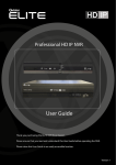
YW-2211 User Manual 深圳市有为信息技术发展有限公司 Shenzhen Yuwei Info&Tech Development Co., Ltd 1 Content 1. GENERAL .......................................................................................................................................................................3 2. PACKING LIST ................................................................................................................................................................3 3. INSTALLATION ...............................................................................................................................................................4 3.1 WIRING DIAGRAM........................................................................................................................................................4 3.2 ATTENTION .................................................................................................................................................................5 3.3 INSTALLATION ..............................................................................................................................................................5 4. FEATURE ........................................................................................................................................................................7 4.1 PHONE CALLING FUNCTION ............................................................................................................................................7 4.2 MULTIMEDIA DRIVING RECORD FUNCTION ........................................................................................ 错误!未定义书签。 4.3 SIGNAL DETECT AND CONTROL ........................................................................................................................................7 4.4 VEHICLE MONITORING FUNCTION ...................................................................................................................................8 4.5 VEHICLE ALARM FUNCTION .......................................................................................................................................... 11 4.6 SMS COMMAND ....................................................................................................................................................... 13 4.7 POWER PROTECTION FUNCTION .................................................................................................................................... 14 5. SPECIFICATION ............................................................................................................................................................ 15 6.FAQ ............................................................................................................................................................................... 16 7.WARRANTY .................................................................................................................................................................. 16 8.CONTACT US ................................................................................................................................................................. 17 2 1. General The Enhanced Mini Blue GPS Tracker is the smallest full-function vehicle positioning terminal with GPRS and SMS dual channel. By connected with extra accessories, it can support Driver Analyzer via IC&RFID card, two-way communication, Photograph record, oil consumption detector, etc. 2. Packing List 2.1 Standard ①Main Unit ②GSM Antenna 1pcs 1pcs ③GPS Antenna 1pcs ④Cable 1set ⑤User Manual ⑥Warranty Card ⑦Certificate Of Approval 2.2 Optional ① Relay ② Speaker 3 3. ③ Digital Camera ④ LCD Display ⑤ Fuel Consumption Detector ⑥ Temperature Detector Installation 3.1 Wiring Diagram 4 3.2 Attention Please make sure the SIM card should be GSM network system and GPRS function must be available. SMS function should be active if necessary. Please choose a proper place to install the device. Don’t install the device where directly over the surface of the metal cover; don’t place the device where can easily get wet and rain. All the connecting should meet the standard of installation and all the bare wire should be wrap by the insulation pipe. If relay is needed, please choose the suitable one(12V/24V) for the right vehicle. As the fuse can protect both for the device and vehicle, you need to connect the fuse if you cut short of the device wire before installation. 3.3 Installation (1)【Choose a best space for the device】 It should not affect the normal operation of the driver; It should not affect the appearance and function of the vehicle itself; Make sure not to shower by the rain or water and it strictly prohibited by water immersion; All kinds of cables shall ensure to be strapped by the insulation pipe; prevent being broken even short circuit; It should avoid direct sunlight Device should be fixed by screw or lock up. (2)【ON/OFF of Backup battery】 Switch to“ON” means battery is open; Switch to “OFF”means battery is closed; Backup battery factory capacity is no less than 70%; For the first time installation, Backup battery will automatically charge to the saturated state; Attention:Don’t switch on the battery before installation or device is not in use 5 (3) Installation of the GSM antenna Install position should be near to car window, as GSM can receive signal well Install position should be hidden in order to avoid destroy Antenna and metal panel should have 5cm distance that car can receive signal well even in high speed. Paste the antenna after choose the suitable install position.(For the D type antenna, paste it on the wheel) Do not crush the antenna cable, or snap it Attention: Use handset check the GSM signal after installation, make sure 3G signal should be above 19 Below 19 should check GSM position. (4)【GPS antenna installation】 Connect antenna & GPS tracker, do not use metal cover antenna, make sure can see 60° sky, gradients should be lower than 15°, better to put antenna near front, back windows or top of the car.( do not install if back window have car window protection film) Antenna (arc side) should be face to the sky, antenna do not use other material to cover it; Antenna bottom (flat, have word) have magnet which can stick on the car, better use double adhesive tape fixed it) Do not crush the antenna cable, or snap it 6 (5)【Status of GPS&GSM signal light】 Red(GPS signal light): 5 seconds flicker once indicates no satellite singnal 5 seconds flicker three times indicate have satellite singal which reach 4 star degree Red light indicate GPS antenna open circuit, pls check GPS antenna connection or cut off it. Yellow (GSM Signal light): 5 seconds flicker once indicate no signal 5 seconds flicker twice indicate have signal but have not connect with the monitoring center. 5 seconds flicker three times indicate have signal and connect with the monitoring center. 10 seconds flicker fast after power on, continue flicker 4 times indicate can not detect the SIM card, need to be pluged and inserted again. 4. Feature 4.1 Phone Calling Function Device can support two-way communication, by making and answering calls. Though sending Monitoring command, the platform can monitor the voice inside the vehicle; TTS voice broadcast function can real-time playing remote dispatch message and the prompt of automatic voice detecting. 4.2 Signal detect and control Smart Engine off function Smart & off electricity/fuel function: Remote cut off vehicle electricity/fuel according vehicle ACC & running speed. 7 Choose a target vehicle-click right-open the menu-choose control order-Engine off function. There are three options. Immediately cut off electricity/fuel will turn off vehicle at once; smart engine off function means first cut off vehicle, turn on again ,then turn off again repeat few times, until the vehicle speed down to safe and then the electricity/fuel is totally turned off. 4.3 Vehicle Monitoring Function Vehicle monitoring function, GEO fence function, historical trajectory function, Mileage statistics function Vehicle monitoring function: Vehicle position reply by fixed time, update vehicle position situation by real time. Setting procedure: 1. click the triangle on the right side, open the function window; 2. Click the function category, switch function setting 3. Set the parameter in the regular monitoring part. Timing monitoring means the device sends position information by a setting interval time. Distance monitoring means the device sends position information by a setting interval distance. 8 GEO-Fence alarm setting: Hardware support 108 rectangle areas (or 20 polygon areas). 9 Geo-fence in alarm: When the car enters an area which is set as forbidden, it will alarm and send alarming to the platform. (Select option when setting areas) Geo-fence out alarm: When the car drives out of an area which is set as safe, it will alarm and send the alarming to the platform. (Select option when setting areas) Realtime Photo:The device take pictures when get alarms or receive the photographing-order from the platform and then upload to the central server. Satellite mileage statistic: Satellite mileage statistic in real time 10 4.4 Vehicle Alarm Function Parking alarm: The platform sends command to device though GPRS; After ACC off, then any illegal door open, ACC on will trigger this alarm and send data to platform. Yaw alarming: Appointed vehicle should run specific appoint route; when vehicle drives away the specific route, it will arouse yaw alarming and send it to the platform. Over speed alarm: When the vehicle speed is over the setting value, it will cause alarm and upload to monitoring center platform accordingly. Platform setting step: Choose vehicle—Click right menu—Choose terminal parameter set—Click set overspeed parameter 11 Fatigue Driving Alarm: If the vehicle driving time is over preset time, it will send fatigue alarm to the control center platform. Setting Procedure: choose one vehicle in vehicle list –click mouse right button-display all the setting –choose terminal parameters set –choose fatigue driver setting 12 4.5 SMS Command Command list: Various functions and parameters can be set by GPRS/SMS commands including turning on/off the device. Meanwhile the unit software can support wireless download and update, namely no need for the users to operate on the device, which improve the efficiency and save time. As below: 13 Command Example Reply Function *=5*29*29;1:1;1*9774, *#5# *#5# 3791*4600003001586 check 2G/3G signal 43*46000 *#60*SIM *#60*3365214211 number# # *#37# *#37# *#37*1# or *#14# *#58*n# *=60*01*3365214211 According to the example, the signal is 29 *#60# check the parameters restart the device without clearing the configuration restart the device and reset *#14# *#58*0# configure the SIM number Remark to manufacturer defaults *=58*01*0 turn on/off the sleep mode n=1 stands for turn on; n=0 stands for turn off Alarm--pre-alarm speed *#160*Alar m*Alert# *#160*70*90# configure *=160*01*70,90 parameters over-speed value; Alert--alarm speed value Unit: KM/H 4.6 Power Protection Function Saving mode: After the car flameout, the device will enter the saving mode, and working current will decline to 15mA@12V. Storage battery over discharge protection: when storage battery voltage is less than 10.5V, it will switch to backup battery to protect the original car battery. Over voltage protection: When the supply voltage is over 60V, It will automatic cut down external circuit to protect the terminal. 14 5.Specification Terminal Property Terminal Use Dual-core central processing chip 3G module GSM communication module Design Battery protection Circuit protection Three anti-paint protection Specification Working Voltage 10~60 V/DC Highest Voltage 100V/DC Storage Battery Voltage Protect Lowest:9V(12V Battery) or 20V(24V Battery) Highest:60V Anti-reverse Power 100V Working current Average:70mA@12V Saving mode current:15mA Backup battery 320mAh Dimensions 72x 55 x 24 mm (L x W x H) Material aluminium alloy Unit net weight 0.12kg Port GPS Antenna SMA port:-26dB GSM Antenna SMAport:-3dB Output 1 route SOS button input 1 route Ignition Detect: 7-60V 1 route high level: 7-60V voice Interface 1 route speak output; 1 route voice input extra equipment power supply interface 1 route RS232 port, including output power DC5V/500mA Environment features Vehicle spark noise immunity Electro-transient pulse Discharge voltage 10 kV~20 kV, discharge frequency 20 times/s~200 times/s noise 4KV, experiment grade IV immunity Static discharge noise immunity Contacting discharge 6KV, air discharge 8KV, experiment grade III Conduction interference limits Accord with the requirements of class B Radiated interference limits Accord with the requirements of class B Temperature Work: -30 ℃ ~ +70 ℃ Storage:-40 ℃ ~ +85 ℃ Humidity 5% ~ 95% Non-condensing GPS Spec Sensitivity -159dBm Locating Time Cold start less 34 sec ,Hot start less 3.5sec ,Moderate Start less 33sec , Locating Accuracy 10m 2DRMS 15 Speed Accuracy 0.1M/sec Data base accuracy 100M Flash memory Blind area storage Flash memory 1400 pcs locate data Preset Road record Flash memory 8 line road data 6.FAQ No State Method Remark 1 Device not display in the 1.Check IP ,PORT ,APN parameters tracking platform 2.Check vehicle data and terminal S/N , 3.Check SIMCARD has enough money or not or open GPRS service 2 No GSM signal 1、 Check SIMCARD insert position correct or not Some SIMCARD not open GPRS 2、 Change another SIMCARD test service ,so please make sure it 3、 SIMCARD is value SIMCARD or overdue open GPRS service first when put them in the cell phone ,then put them back to the device 3 4 5 6 There the 1. GPS don’t locate, There is no enough Satellite map ,but no detail position signal, please check GPS antenna position 2. Vehicle display Data incorrect When engine off ,There is The relay red wire and green wire connect wrong , sound from Relay please follow the wiring diagram reconnect There is is device no in Speed and 1、 Check ACC wire connect mileage data of device 2、 Reconnect ACC wire SIMCARD less money ,but 1、 After recharge SIMCARD ,SIMCARD must login after recharge ,device still not again online Though center send command *#37# to device and restart. 7 There is no CAR ID display Before install the SD card ,please set up the vehicle ID when playing the video of data ,then when record data ,the CAR ID data will the SD card display 7.Warranty After Sale Service This system has been tested before sold, we ensure it can work stable below low or high temperature. We 16 strongly recommend you to get this system installed by professional. There is a one-year warranty except the following condition: 1. Installation, or connect wire broken by personally or unprofessional. 2. Warranty will eliminate if the ownership of the tracker has been changed. 3. Parts damaged or lost by man-made 4. Battery, adapter, wires, etc. Warning: this device is just auxiliary a product that applying the location of current object, we have no responsibility if you have damage or lost in using this tracker. Under the copyright laws, this manual may not be copied, in whole or in part, without the written consent of YUWEI. 8. Contact Us: Shenzhen Yuwei Information & Technology Development Co., Ltd Address: Floor 6, Taike Building No.2 Taike Road, Futian district , Shenzhen China Tel::0755-83123345 Fax:0755-53105544 Website:http://www.yuweigps.com 17