1
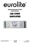
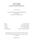
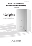
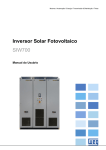
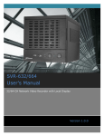
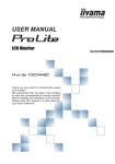
Accessories User Manual for iAMP-700 (Preliminary) Contents 1 1 Germany & Other Countries Laser Components GmbH Tel: +49 8142 2864 – 0 Fax: +49 8142 2864 – 11 [email protected] www.lasercomponents.com 1. Important remarks 2 2. Technical data 2 2.1. General 2 2.2. Absolute maximum ratings 2 2.3. Connectors 2 2.4. Test conditions 3 2.5. Gain settings 3 2.6. Connector configuration 4 2.6.1. Power supply 4 2.6.2. RS232 4 2.7. Dimensions 5 2.8. Connecting die iAMP-700 5 2.9. Signal input 6 2.10. Signal output and PSU connection 7 2.11. RS232 port 7 3. Starting up the iAMP-700 7 3.1. Important remark 7 3.2. Step1: Connecting the iAMP-700 correctly 7 3.3. Step 2: Operation via keypad 8 4. The keyboard 8 4.1. General information 8 4.2. Operation via keypad 9 4.2.1. Display 1 9 4.2.2. Display 2 9 4.2.3. Displays 3 and 4: Overview of current settings of the i-AMP 9 4.2.4. Display 5: Setting the bias voltage 10 4.2.5. Display 6: Setting the offset voltage 10 4.2.6. Display 7: Setting the gain 10 4.2.7. Display 8: High-speed-mode or Low-speed-mode 10 4.2.8. Display 9: AC or DC 10 4.2.9. Display 10: Full bandwidth or low pass filter 11 4.2.10. Display 11: Saving the current gain settings 11 Accessories User manual for IAMP-700 2 Germany & Other Countries Laser Components GmbH Tel: +49 8142 2864 – 0 Fax: +49 8142 2864 – 11 [email protected] www.lasercomponents.com 5. Operation via RS232 Interface 11 5.1. General information 11 5.2. Default Interface 11 5.3. Table of Functions 12 5.4. Direct control 13 6. Applications: Current measurement 13 6.1. Task 13 6.2. Setup 14 6.3. Carrying out the measurements 14 6.3.1. Measurement 1 14 6.3.2. Measurement 2 15 6.3.3. Measurements 3 to 7 15 6.3.3.1 Measurement 3 15 6.3.3.2 Measurement 4 16 6.3.3.3 Measurement 5 16 6.3.3.4 Measurement 6 16 6.3.3.5 Measurement 7 17 6.3.4. Measurement 8 17 6.3.5. Measurement 9 18 6.3.6. Measurement 10 19 7. Example: Measurement of laser pulses with a photodiode 19 7.1. Task 19 7.2. Experimental setup 20 7.3. Measurement 20 7.3.1. Measurement 1 20 7.3.2. Measurements 2 to 5 21 7.3.2.1 Measurement 2 21 7.3.2.2 Measurement 3 21 7.3.2.3 Measurement 4 22 7.3.2.4 Measurement 5 22 7.4. Analysis of measurement data 22 8. Applications 23 8.1. iAMP-700 with PIN-Diode 23 8.2. iAMP-700 with dBC module and APD 24 8.3. iAMP-700 with ABC-module and APD 24 9. Appendix 25 Accessories User manual for IAMP-700 1. Important remarks The iAMP-700 is a transimpedance ampflifier and can therefore only amplify currents but no voltages. It is necessary to check if the bandwidth is sufficient for a sensible use of the iAMP-700. It is important to note that the bandwidth of the amplifier decreases with increasing amplification (see section 2.5). With amplifications from 10^2 to 10^3 the bandwidth of the iAMP-700 is 720kHz. The iAMP-700 has the possibility for the output to be grounded (GND) with a resistor which means that the amplified input signal will not be given out (inactive output). This is part of the basic settings of the iAMP-700 when being switched on. In order to perform measurements the output needs to be activated with the button “OUT” (button 6, see section 4.1). 2. Technical Data 2.1 General ±15 V +5 V Operation 0…+60 °C Storage -40…+100 °C Supply voltage Temperature Table 1: General technical data It is recommended to use the i-AMP-PSU. 2.2 Absolute maximum ratings Signal input current ±40 mA Transient input voltae ±3 kV Power supply voltage ±25 V Table 2: Absolute maximum ratings 2.3 Connectors Signal input BNC Singnal output BNC Power supply LEMO ERA.2S.305.CLL RS232 D-Sub 9-pin male Table 3: Connectors 3 Germany & Other Countries Laser Components GmbH Tel: +49 8142 2864 – 0 Fax: +49 8142 2864 – 11 [email protected] www.lasercomponents.com Accessories User manual for IAMP-700 2.4 Test conditions Test conditions Gain Frequency response Input Output VS= ±15 V and +5 V, Ta= 25°C Transimpedance 102 - 1011 V/A Gain accuracy ±1 % Gain drift see table below Lower cut-off frequency DC / 1 Hz Upper cut-off frequency Up to 720 kHz (see table below), switchable to 10 Hz Gain flatness ±0.1 Equivalent input noise current see table below (value per √Hz, @ 500 Hz) Equivalent input noise voltage 4 nV/√Hz (@ 100 Hz) Input offset current drift see table below Input bias current 1 pA typ. (max. 3 pA) Max. input current see table below (value for linear amplification) Input offset compensation adjustable by control Output voltage ± 10 V (@>10 kΩ load) Output impedance 50 Ω (terminate with > 10 kW load for best performance) Max. output current ± 100 mA Detector bias Bias voltage range Offsett control Control voltage range dB 10 V, max. ± 100 mA ± 10 V Table 4: Test conditions 2.5 Gain settings Table Gain Setting: “Low Noise“ 102 103 104 105 106 107 108 109 V/A Upper cut--off frequency 720 720 480 480 72 72 1.6 1.6 kHz Rise/Fall Time (10%-90%) 0.5 0.5 0.7 0.7 5 5 200 200 µs Equivalent input noise current 26 24 2.6 2.2 0.28 0.26 0.009 0.009 pA 100000 10000 1000 100 10 1 0.1 0.01 µA 1000000 100000 10000 1000 100 10 1 0.1 nA 50 50 50 50 150 150 10000 10000 Ω Max. input current Input offset compensation range DC input impedance (//5pF) 4 Germany & Other Countries Laser Components GmbH Tel: +49 8142 2864 – 0 Fax: +49 8142 2864 – 11 [email protected] www.lasercomponents.com Accessories User manual for IAMP-700 Table Gain Setting: “High Speed“ 104 105 106 107 108 109 1010 1011 V/A Upper cut--off frequency 720 720 480 480 72 72 1.6 1.6 kHz Rise/Fall Time (10%-90%) 0.5 0.5 0.7 0.7 5 5 200 200 µs Equivalent input noise current 26 24 2.6 2.2 0.28 0.26 0.009 0.009 pA Max. input current 1000000 100000 10000 1000 100 10 1 0.1 nA Input offset compensation range 1000000 100000 10000 1000 100 10 1 0.1 nA 50 50 50 50 150 150 10000 10000 Ω DC input impedance (//5pF) 2.6 Connector Configuration 2.6.1 Power supply PIN Connection 1 -15 V 2 GND 3 +15 V 4 +5 V 5 GND Fig. 1: Pinning LEMO connector 2.6.2 RS232 5 Germany & Other Countries Laser Components GmbH Tel: +49 8142 2864 – 0 Fax: +49 8142 2864 – 11 [email protected] www.lasercomponents.com PIN Bezeichnung 1 NC 2 RXD 3 TXD 4 NC 5 GND 6 NC 7 NC 8 NC 9 NC Fig. 2: RS232 Pinning of Sub-D connector Accessories User manual for IAMP-700 2.7 Dimensions Fig. 3: Dimensions, keyboard and signal input 2.8. Connecting the iAMP-700 ▪▪ 2x BNC (current input, voltage output) ▪▪ 1x D-Sub 9-pin male (for RS232) ▪▪ 1x LEMO ERA.2S.305.CLL (power supply) Remarks: ▪▪ Bias voltage is available from the outer sleeve of the BNC input. The bias voltage can be set in the range -10 V to +10 V. At 0 V bias, the sleeve is connected to ground via an internal relay. ▪▪ The bias voltage allows straightforward operation of the iAMP with a PIN photodiode. ▪▪ The outer sleeve of the BNC output is at GND. ▪▪ The inner contact of the output BNC is connected to ground via 10 kOhm when inactive (no output signal). ▪▪ RS232 operation is described in section 5. 6 Germany & Other Countries Laser Components GmbH Tel: +49 8142 2864 – 0 Fax: +49 8142 2864 – 11 [email protected] www.lasercomponents.com Accessories User manual for IAMP-700 Signal output Signal input RS232 for communication with a PC Fig. 4: Connecting th iAMP-700 2.9 Signal input Input Biasvoltage Signal (current) Fig. 5: Signal input The bias voltage can be set between -10V and +10V with reference to GND. 7 Germany & Other Countries Laser Components GmbH Tel: +49 8142 2864 – 0 Fax: +49 8142 2864 – 11 [email protected] www.lasercomponents.com Accessories User manual for IAMP-700 2.10 Signal output and PSU connection PSU connector Output GND Signal (voltage) Fig. 6: Signal output 2.11 RS232 port RS232 port Fig. 7: RS232 port 3. Starting up the iAMP-700 3.1 Important remark Before starting up the iAMP-700 read this manual carefully. With this, many operating errors can be prevented. 3.2 Step 1: Connecting the iAMP-700 correctly The iAMP-700 is to be connected in the following way: 1. 2. 3. 4. 8 Germany & Other Countries Laser Components GmbH Tel: +49 8142 2864 – 0 Fax: +49 8142 2864 – 11 [email protected] www.lasercomponents.com Connect the PSU with the PSU connector Connect the signal source with the signal input Connect the signal output with the read-out device (for example oscilloscope, voltmeter, etc.). If digital control is requested connect the iAMP-700 via RS232 port to the PC Accessories User manual for IAMP-700 3.3 Step 2: Operation via keypad In most cases it is recommended to activate the signal output with pressing button 6. This should be done before altering any of the settings of the iAMP-700. 4. The keypad 4.1 General information Button 1 Button 2 Button 3 Button 4 Button 5 Button 6 Fig. 8: Keypad of the iAMP-700 The buttons 1 to 4 allow to navigate through the different menu items. Buttons 2 and 3 allow setting of different values for bias voltage, offset voltage and amplification. Moreover, button 2 and 3 allow to choose between different functions like high speed/ low noise, AC/DC coupling and lowpass filter. With button 5 settings can be confirmed or a reset can be carried out with holding down the button for a few seconds. Button 6 activates or deactivates the signal output. Only when the signal output is activated an output signal can be measured. 9 Germany & Other Countries Laser Components GmbH Tel: +49 8142 2864 – 0 Fax: +49 8142 2864 – 11 [email protected] www.lasercomponents.com Accessories User manual for IAMP-700 4.2 Operation via keypad 4.2.1 Display 1 When starting up the iAMP-700 the device runs through a starting routine which activates the basic settings and deactivates the output port. The starting display can be seen in Fig. 9. Navigation through the different menu items is done with buttons 1 to 4. Fig. 9: Starting display; Display 1 4.2.2 Display 2 After pressing button 4 the following display appears (Fig. 10). Here prior settings that were saved can be chosen. Fig. 10: Display 2 4.2.3 Displays 3 and 4: Overview of current settings of the i-AMP After pressing button 4 again displays 3 and 4 are shown. These two displays show an overview of the current settings of the i-AMP. Here, these settings cannot be changed. In display 3 the gain is shown with “G:1E+02” which means that the gain is: Fig. 11: Display 3 G=1E + 2 = 1 ∙ 102 = 100 The combination of letters (here: „LNDCFBW“) gives information about the status of three different functions of the amplifier: Display 10 Germany & Other Countries Laser Components GmbH Tel: +49 8142 2864 – 0 Fax: +49 8142 2864 – 11 [email protected] www.lasercomponents.com Explanation LNDCFBW Low Noise DC-coupled Full bandwidth, low pass filter disabled HSDCFBW High Speed DC-coupled Full bandwidth, low pass filter disabled LNACFBW Low Noise AC-coupled Full bandwidth, low pass filter disabled HSACFBW High Speed AC-coupled Full bandwidth, low pass filter disabled LNDC10Hz Low Noise DC-coupled Bandwidth limited to 10 Hz, low pass filter enabled HSDC10Hz High Speed DC-coupled Bandwidth limited to 10 Hz, low pass filter enabled LNAC10Hz Low Noise AC-coupled Bandwidth limited to 10 Hz, low pass filter enabled HSAC10Hz High Speed AC-coupled Bandwidth limited to 10 Hz, low pass filter enabled Table 6: Display explanation Fig. 12: Display 4 Accessories User manual for IAMP-700 4.2.4 Display 5: Setting the bias voltage Display 5 shows the index value of the bias voltage. Here, the value of the bias voltage can be changed. In the case displayed in Fig. 13 the index value is 0.00 V. The setting of the bias voltage is done by pushing buttons 2 and 3. Holding down these buttons increases the velocity of setting these values. Fig. 13: Displyay 5 The index value of the bias voltage can be set from -10V to + 10V. Once the desired value is chosen pressing button 4 changes the menu to display 6. 4.2.5 Display 6: Setting the offset voltage Analogous to the bias voltage the offset voltage can be set to an index value. It is important to note that the value of the offset voltage is a relative parameter and not absolute. This means that when setting the value to +5V not really 5V are set but 50% of the possible positive offset voltage value. How to use the offset voltage appropriately is shown in the detailed example in section 6.3.4. Fig. 14: Display 6 4.2.6 Display 7: Setting the gain Displayed here is the current gain which can be set using the buttons 2 and 3. If the amplifier is run in low-noise-mode gains in the range from 10² V/A to 109 V/A can be set. If changed into the high-speed-mode the gain region changes from 104 V/A to 1011 V/A. Fig. 15: Display 7 4.2.7 Display 8: High-speed-mode or Low-speed-mode When this menu is selected the user can choose between low-noise-mode and high-speed-mode. The high-speed-mode offers a higher bandwidth than the low-speed-mode when the gain is identical which can be helpful when working with fast signals. However, the signal-to-noise ratio deteriorates in this case. Very small signals can be illustrated very well with a frequency < 10 Hz in high-speed-mode with a gain of 10^11 along with a low pass filter. The customer can change between the low-noise and high-speed-mode with buttons 2 and 3. Fig. 16: Display 8 4.2.8 Display 9: AC or DC In the basic settings the i-AMP-700 is DC coupled, without high pass filter. If necessary a high pass filter can be activated (AC-coupling). This selection between DC and AC coupling can be made with buttons 2 and 3. 11 Germany & Other Countries Laser Components GmbH Tel: +49 8142 2864 – 0 Fax: +49 8142 2864 – 11 [email protected] www.lasercomponents.com Fig. 17: Display 9 Accessories User manual for IAMP-700 4.2.9 Display 10: Full bandwidth or low pass filter With the help of low pass filters (Tschebyscheff 8th order) the bandwidth can be reduced to 10Hz. The achievement is better signal illustration. With buttons 2 and 3 the filter can be activated or deactivated. After the choice is made pressing the button 4 changes the menu to display 11. Fig.18: Display 10 4.2.10 Display 11: Saving the current gain settings With the i-AMP-700 up to 5 complete gain settings can be saved. Each one of these settings can be reactivated after the start-up of the device. These settings can be reactivated using display 2. To save the current settings of the i-AMP-700 the customer needs to choose either “No!” or “Yes!” with buttons 2 and 3. Afterwards the selection is confirmed with the ENTER-button (button 5) which shows display 11. Fig. 19: Display 11 With buttons 2 and 3 the customer can choose the memory location. The preferred location is selected with the ENTER-button and display 2 is shown. If the customer does not want to choose a setting pressing button 4 leads to the next display which is display 1 in this case. With button 1 the prior display can be set. Fig. 10: Display 12 5. Operation via RS232 Interface 5.1 General information The information provided here are of a very general kind. Special information about the usage of the digital interface and the LabView- driver with interface will be given in a separate manual. Important: To control the i-AMP-700 via RS232 a D-Sub cable, 9-pin, female/female with 1:1 connection is necessary. A “Null-modem-cable” does not work. Operation with a “USB to Serial Converter” is possible. 5.2 Default Interface RS232 (RxD, TxD) 12 Germany & Other Countries Laser Components GmbH Tel: +49 8142 2864 – 0 Fax: +49 8142 2864 – 11 [email protected] www.lasercomponents.com Baud rate: 9600 8 bits No parity No flow control Remote operation of the iAMP via RS232 requires a 9-pin D-sub cable. USB operation using a USB to serial converter is also possible. Accessories User manual for IAMP-700 5.3 Table of Functions Function RS232 command Description UBias (-10 V bis +10 V) b˽xxxx Bias voltage UOffset o˽xxxx Offset voltage Gain g˽xx Gain 10xx A/V xx ∈ {3;4;…;11} a˽0 a˽1 AC/DC: high pass DC on AC on h˽0 h˽1 Low Noise / High Speed Low Noise (gain setting range 102 to 109) High Speed (gain setting range 104 bis 1011) t˽0 t˽1 Tschebyschow low pass filter (10 Hz) off on x˽0 x˽1 Output switching Output connected to ground via resistive load Output active AC/DC High Speed TTPF OUT Save State s˽xx Saves current setup xx: 01…05 (memory location number) Recall State r˽xx Recalls saved setup xx: 01…05 (memory location number) Riegel R˽0 R˽1 Disables keypad deactivated (keypad operation is also permitted) activated (keypad disabled; operation via RS232 only) Help H Lists all commands State H Display the current setup Table 7: RS232 Commands RS232-commands: „ ˽ “ = „space“; If a command’s numerical appendix is replaced by a „?“ the current parameter value is returned as the reply (does not apply to commands in described in red above). Space does not need to be set if a value is written after a command. ▪▪ Example: g˽? Command GAIN: 1E+02 Reply 13 Germany & Other Countries Laser Components GmbH Tel: +49 8142 2864 – 0 Fax: +49 8142 2864 – 11 [email protected] www.lasercomponents.com Accessories User manual for IAMP-700 5.4 Direct control In order to directly control the i-AMP-700 via RS232 a simple terminal program is recommended. As soon as the connection is established and the i-AMP-700 is up and running a welcome screen appears. This is to show the customer that the connection between PC and i-AMP-700 is established and functioning. The commands mentioned in table 7 can be entered here. Consequently, the state of the changed parameter is displayed if the command was entered correctly and was processed by the i-AMP-700. Welcome screen Command: Gain should be 1E+08 Answer: Gain is 1E+08 Command: Gain inquiry Answer: Error (Space missing) Command: Gain inquiry Answer: Gain is 1E+08 Command: Deactivate output Answer: Output inactive Output is on GND Fig. 21: Terminal program 6. Applications: Current measurement 6.1 Task Different currents are to be measured from a current source (here: Keithley 220) with the i-AMP-700 and an oscilloscope (here: Agilent MSO7104A) to show the voltage signal. The signals are of rectangular pulse shape with a duty cycle of 50%. The values of the different currents with repetition frequency are listed in the table below: 14 Germany & Other Countries Laser Components GmbH Tel: +49 8142 2864 – 0 Fax: +49 8142 2864 – 11 [email protected] www.lasercomponents.com Measurement High Low Frequency 1 +10 mA -10 mA 100 Hz 2 +1 mA -1 mA 100 Hz 3 +100 μA -100 μA 100 Hz 4 +10 μA -10 μA 100 Hz 5 +1 μA -1 μA 100 Hz 6 +100 nA -100 nA 100 Hz 7 +10 nA -10 nA 100 Hz 8 +2 nA -2 nA 100 Hz 9 +500 pA -500 pA 1 Hz 10 +50 pA -50 pA 1 Hz Table 8: List of current and repetition frequencies Accessories User manual for IAMP-700 6.2 Setup ▪▪ ▪▪ ▪▪ ▪▪ Current source: Keithley 220 Oscilloscope: Agilent MSO7104A Current-voltage-amplifier: i-AMP-700 Power supply unit: i-AMP-PSU Current source Oscilloscope Fig. 22: Setup 6.3 Carrying out the measurments 6.3.1 Measurement 1 Step 1: Starting up the measurement. Display 1 (see section 4.2.1) is shown on the i-AMP-700. Output must be activated by pushing button 6. Step 2: Button 4 needs to be pushed 5 times to get to display 6 (see section 4.2.6) . Here the offset voltage is set. It is set to -0.39V and like this fits nicely to the gain which is 1E+02. Summary of settings: ▪▪ ▪▪ ▪▪ ▪▪ ▪▪ ▪▪ ▪▪ 15 Germany & Other Countries Laser Components GmbH Tel: +49 8142 2864 – 0 Fax: +49 8142 2864 – 11 [email protected] www.lasercomponents.com Output inactive Gain: 1E+02 Bias: 0.0V Offset: -0.36V Low-noise-mode Coupling: DC Low pass filter: off Fig. 23: Measurement 1; signal on oscilloscope for measurement 1 Accessories User manual for IAMP-700 6.3.2 Measurement 2 Step 1: Starting up the measurement. Display 1 (see section 4.2.1) is shown on the i-AMP-700. Output must be deactivated with pushing button 6. Step 2: Button 4 needs to be pushed 6 times to get to display 7 (see section 4.2.7.). Here the gain is set. Optimum gain in this case is 10^3 V/A (1E+03). To be able to set this value, the customer needs to hold down button 2 for a few seconds. On the oscilloscope a small shift of the signal to the top is shown. This can be corrected with varying the offset voltage. Step 3: Pushing button 1 changes the screen to display 6. Here the offset voltage is set. It is set to -0.10V and like this fits nicely to the gain which is 1E+03. With pushing button 3 several times the desired value can be set. The signal curve moves slowly to the bottom. Summary of settings: ▪▪ ▪▪ ▪▪ ▪▪ ▪▪ ▪▪ ▪▪ Output active Gain: 1E+03 Bias: 0.0V Offset: -0.10V Low-noise-mode Coupling: DC Low pass filter: off Fig. 24: Measurement 2; signal on oscilloscope for measurement 2 6.3.3 Measurements 3 to 7 Measurements 3 to 7 are similar to measurement 2 (see section 6.3.2). Only the gain values have to be chosen differently. This leads to a different setting of the offset voltage as well. Regarding measurements 3 to 7 only the results as well as the summary of the settings will be mentioned in the following. 6.3.3.1 Measurement 3 Summary of settings: ▪▪ ▪▪ ▪▪ ▪▪ ▪▪ ▪▪ ▪▪ Output active Gain: 1E+04 Bias: 0.0V Offset: -0.35V Low-noise-mode Coupling: DC Low pass filter: off Fig. 25: Signal on oscilloscope for measurement 3 16 Germany & Other Countries Laser Components GmbH Tel: +49 8142 2864 – 0 Fax: +49 8142 2864 – 11 [email protected] www.lasercomponents.com Accessories User manual for IAMP-700 6.3.3.2. Measurement 4 Summary of settings: ▪▪ ▪▪ ▪▪ ▪▪ ▪▪ ▪▪ ▪▪ Output active Gain: 1E+05 Bias: 0.0V Offset: -0.10V Low-noise-mode Coupling: DC Low pass filter: off Fig. 26: Signal on oscilloscope for measurement 4 6.3.3.3 Measurement 5 Summary of settings: ▪▪ ▪▪ ▪▪ ▪▪ ▪▪ ▪▪ ▪▪ Output active Gain: 1E+06 Bias: 0.0V Offset: -0.35V Low-noise-mode Coupling: DC Low pass filter: off Fig. 27: Signal on oscilloscope for measurement 5 6.3.3.4 Measurement 6 Summary of settings: ▪▪ ▪▪ ▪▪ ▪▪ ▪▪ ▪▪ ▪▪ Output active Gain: 1E+07 Bias: 0.0V Offset: -0.06V Low-noise-mode Coupling: DC Low pass filter: off Fig. 28: Signal on oscilloscope for measurement 6 17 Germany & Other Countries Laser Components GmbH Tel: +49 8142 2864 – 0 Fax: +49 8142 2864 – 11 [email protected] www.lasercomponents.com Accessories User manual for IAMP-700 6.3.3.5 Measurement 7 Summary of settings: ▪▪ ▪▪ ▪▪ ▪▪ ▪▪ ▪▪ ▪▪ Output active Gain: 1E+08 Bias: 0.0V Offset: -1.34V Low-noise-mode Coupling: DC Low pass filter: off Fig. 29: Signal on oscilloscope for measurement 7 6.3.4 Measurement 8 The initial steps for this measurement are the same as for the prior measurements. After setting the gain to 109 V/A (1E+09) the oscilloscope shows the following picture: The influence of the offset voltage is clearly visible. Without changing the offset voltage accordingly the measurement will not lead to any useful results. Therefore, the offset voltage needs to be changed. After switching to display 6 (see section 4.2.5) the offset voltage value can be set by pushing button 3. The offset voltage can now be set to -7.42 V. Fig. 30: Signal on oscilloscope for measurement 8 without adjustment of offset voltage Summary of settings: ▪▪ ▪▪ ▪▪ ▪▪ ▪▪ ▪▪ ▪▪ Output active Gain: 1E+09 Bias: 0.0V Offset: -7.42V Low-noise-mode Coupling: DC Low pass filter: off Fig. 31: Signal on oscilloscope after adjustment of offset voltage 18 Germany & Other Countries Laser Components GmbH Tel: +49 8142 2864 – 0 Fax: +49 8142 2864 – 11 [email protected] www.lasercomponents.com Accessories User manual for IAMP-700 6.3.5 Measurement 9 For this measurement it is necessary to switch from low-noise-mode to high-speed-mode because in this mode gains of 1010 V/A and 1011 V/A are possible. For this, display 8 has to be activated (see section 4.2.7). One can change between low-noise-mode and high-speed-mode by pushing buttons 2 and 3. In the next step, the gain has to be set to 1010 V/A in display 7 (see section 4.2.6), where the output of the amplifier reaches the upper limit (+12V), see fig, 32. To be able to perform a measurement reasonably, the offset voltage has to be decreased. This is possible when activating display 6 (see section 4.2.5). After setting the offset voltage to -1.29 V the oscilloscope shows the following picture (Fig. 33): Fig. 32: Signal on oscilloscope for measurement 9 without adjustment of offset voltage The picture shows the influence of the high gain on the signal noise without reduction of the bandwidth. At this point the lowpass filter needs to be activated since the signal frequency is 1 Hz which is significantly smaller than the 10 Hz the low-pass filter is limited to. Fig. 33: Signal on oscilloscope for measurement 9 with adjustment of offset voltage but without low-pass-filter To activate the low-pass filter display 10 needs to be chosen (see section 3.2.9). To activate or deactivate the low-pass filter push buttons 2 and 3. The signal on the oscilloscope changes as shown in fig. 34 when the low-pass filter is activated. Summary of settings: ▪▪ ▪▪ ▪▪ ▪▪ ▪▪ ▪▪ ▪▪ Output active Gain: 1E+10 Bias: 0.0V Offset: -1.29V High-speed-mode Coupling: DC Low pass filter: on Fig. 34: Signal on oscilloscope for measurement 9 with adjusted offset and with low-pass-filter 19 Germany & Other Countries Laser Components GmbH Tel: +49 8142 2864 – 0 Fax: +49 8142 2864 – 11 [email protected] www.lasercomponents.com Accessories User manual for IAMP-700 6.3.6 Measurement 10 Conducting this measurement is the same as with measurement 9. Therefore, we only mention the summary of the settings: Summary of settings: ▪▪ ▪▪ ▪▪ ▪▪ ▪▪ ▪▪ ▪▪ Output active Gain: 1E+11 Bias: 0.0V Offset: -7.48V High-speed-mode Coupling: DC Low pass filter: on Fig. 35: Signal on oscilloscope for measurement 10 7. Example: Measurement of laser pulses with a photodiode 7.1 The task The task is to detect laser pulses at a wavelength of 405nm with a photodiode. The output current of the photodiode is to be converted to amplified voltage pulses using the iAMP-700. The output voltage signal is then to be displayed on an oscilloscope. A filter is placed between the laser and the photodiode which allows for the transmittance to be varied. Detailed information about the transmittance of the filter can be seen in table 9. Measurement Transmittance of filter Repetition frequency 1 100% (no filter) 100 Hz 2 32% 100 Hz 3 16% 100 Hz 4 10% 100 Hz 5 2% 100 Hz Table 9: list of filters The voltage supply of the photodiode is to be taken from the bias voltage of the iAMP-700. The laser pulse is of rectangular shape with a duty cycle of 50% and a repetition rate of 100 Hz. 20 Germany & Other Countries Laser Components GmbH Tel: +49 8142 2864 – 0 Fax: +49 8142 2864 – 11 [email protected] www.lasercomponents.com Accessories User manual for IAMP-700 7.2 Experimental setup ▪▪ ▪▪ ▪▪ ▪▪ ▪▪ Laser: wavelength: 405nm, P_opt= 1.8mW; PSU for laser: GW Instek GPS 4303 Trigger source: Agilent 3320A Photodiode: EPD-440-0-1.45 Oscilloscope: Agilent MSO7104A PSU Oscilloscope Fig. 36: Experimental setup 7.3 Measurement 7.3.1 Measurement 1 Step 1: Starting up the measurement. Display 1 (see section 4.2.1) is shown on the i-AMP-700. Output must be activated by pushing button 6. Step 2: Bias voltage is to be set to +5.0V. To achieve this, display 5 needs to be activated by pressing button 4 (see section 4.2.4). Starting from display 1 button 4 needs to pressed 4 times. The index value of 0.0V is shown. By holding down button 2 this value needs to be changed to 5.0V. Step 3: Gain is set to 104 (1E+04) by changing to display 7 (see section 4.2.6). To achieve this, button 4 needs to be pushed twice. The gain value shown is 102 (1E+02) and is changed to 104 by pushing button 2. Step 4: Finally, the offset voltage is set in a way that the base of the signal is 0.0V. To achieve this, the customer needs to switch from display 7 to display 6 by pressing button 1 (see section 4.2.5). The necessary offset voltage is -0.36V and is set by pushing button 3. 21 Germany & Other Countries Laser Components GmbH Tel: +49 8142 2864 – 0 Fax: +49 8142 2864 – 11 [email protected] www.lasercomponents.com Accessories User manual for IAMP-700 Summary of settings: ▪▪ ▪▪ ▪▪ ▪▪ ▪▪ ▪▪ ▪▪ Output active Gain: 1E+04 Bias: +5.0V Offset: -0.36V Low-noise-mode Coupling: DC Low pass filter: off Fig. 37: Signal on oscilloscope for measurement 1 7.3.2 Measurements 2 to 5 Measurements 2 to 5 are similar to measurement 1. Therefore, only the summary of the settings will be shown in the following. For measurements 3 and 4 the i-AMP 700 settings stay the same as with measurement 2, only the transmittance of the filter changes (see table 9). 7.3.2.1 Measurement 2 Summary of settings: ▪▪ ▪▪ ▪▪ ▪▪ ▪▪ ▪▪ ▪▪ Output active Gain: 1E+05 Bias: +5.0V Offset: -0.09V Low-noise-mode Coupling: DC Low pass filter: off Fig. 38: Signal on oscilloscope for measurement 2 7.3.2.2 Measurement 3 ▪▪ ▪▪ ▪▪ ▪▪ ▪▪ ▪▪ ▪▪ 22 Germany & Other Countries Laser Components GmbH Tel: +49 8142 2864 – 0 Fax: +49 8142 2864 – 11 [email protected] www.lasercomponents.com Output active Gain: 1E+05 Bias: +5.0V Offset: -0.09V Low-noise-mode Coupling: DC Low pass filter: off Accessories User manual for IAMP-700 7.3.2.3 Measurement 4 Summary of settings: ▪▪ ▪▪ ▪▪ ▪▪ ▪▪ ▪▪ ▪▪ Output active Gain: 1E+05 Bias: +5.0V Offset: -0.09V Low-noise-mode Coupling: DC Low pass filter: off Fig. 40: Signal on oscilloscope for measurement 4 7.3.2.4 Measurement 5 Summary of settings: ▪▪ ▪▪ ▪▪ ▪▪ ▪▪ ▪▪ ▪▪ Output active Gain: 1E+06 Bias: +5.0V Offset: -0.36V Low-noise-mode Coupling: DC Low pass filter: off Fig. 41: Signal on oscilloscope 7.4 Analysis of measurement data The results of the measurements are displayed in table 9. Sensitivity S [A/W] Voltage amplitude UAmpl [V] Gain kiAMP [V/A] Transmittance T Power Popt [mW] Measurement 1 0,1 1,410 10000 1,00 1,41 Measurement 2 0,1 4,710 100000 0,32 1,47 Measurement 3 0,1 2,257 100000 0,16 1,41 Measurement 4 0,1 1,478 100000 0,10 1,48 Measurement 5 0,1 3,044 1000000 0,02 1,52 Table 9: Measurement results 23 Germany & Other Countries Laser Components GmbH Tel: +49 8142 2864 – 0 Fax: +49 8142 2864 – 11 [email protected] www.lasercomponents.com Accessories User manual for IAMP-700 According to the data sheet of EPD-440-0-1.4 the sensitivity of the photodiode is around 0.1 A/W. The voltage amplitude was measured with the oscilloscope. The gain of the iAMP-700 was set in each measurement and the transmittance of the filter is known. From these values one can calculate the laser power with using the following formula: Popt = U Ampl kiAMP ⋅ S ⋅ T Important: In section 6.2 the optical power of the laser was said to be 1.8mW. This value cannot be fully achieved due to several reasons: ▪▪ The experimental setup does not feature any exact focusing of the laser onto the active area of the photodiode. The spot size of the laser beam is in fact larger than the active area, therefore the full power of the laser is not measured. ▪▪ The photodiode is a semiconductor. Therefore, the sensitivity mentioned in the data sheet can vary. ▪▪ The filters used are grey filters and their transmittance was not measured for 405nm but for 510nm. 8. Applications 8.1. iAMP-700 with PIN-Diode Oscilloscope Fig. 43: i-AMP-700 with PIN-Diode 24 Germany & Other Countries Laser Components GmbH Tel: +49 8142 2864 – 0 Fax: +49 8142 2864 – 11 [email protected] www.lasercomponents.com Accessories User manual for IAMP-700 8.2. iAMP-700 with dBC module and APD Oscilloscope Fig. 44: iAMP-700 with dBC and APD 8.3. iAMP-700 with ABC-module and APD The output voltage of the ABC-module is taken from the bias voltage of the iAMP-700. Oscilloscope Fig. 45: iAMP-700 with ABC and SAR500 25 Germany & Other Countries Laser Components GmbH Tel: +49 8142 2864 – 0 Fax: +49 8142 2864 – 11 [email protected] www.lasercomponents.com Accessories User manual for IAMP-700 9. Appendix Display Content Explanation 1 LASER COMPONENTS iAMP-700 Device is ready 2 Recall State? YES! Press ENTER! Activate saved setting 2a Recall State: State 01 Choice of 5 saved settings 3 iAMP SETTINGS: G:1E+02 LNDCFBW Overview of current settings (Part 1) 4 Bias[V]: 03.50 Offset[V]: 00.00 Overview of current settings (Part 2) 5 BIAS-Voltage ADJ VALUE [V]: 03.50 Setting the bias voltage 7 OFFSET-Voltage VALUE [V]: 00.00 Setting the offset voltage 8 GAIN-Adjustment: GAIN: 1E+02 Setting the gain 9 L.NOISE/H.SPEED: VALUE: Low Noise Setting low-noise-mode or high-speed-mode 10 AC/DC COUPLING: VALUE: DC Setting the coupling 11 Lowpass Filter: Filter OFF Setting the low pass filter 12 Save Settings? NO! PRESS ENTER! Save current settings 12a Allocated Space: State 01 Enter? choice between 5 saving spaces 09/14 / V1 / IF / lce/iamp-700-user-manual Table 10: Overview of displays 26 Germany & Other Countries Laser Components GmbH Tel: +49 8142 2864 – 0 Fax: +49 8142 2864 – 11 [email protected] www.lasercomponents.com