1
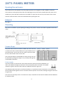
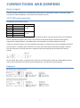
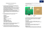
Nokeval 2071 User Manual CONTENTS Document information ...................................................................................................................................... 2 Introduction ....................................................................................................................................................... 3 Manufacturer..................................................................................................................................................... 3 2071 panel meter .............................................................................................................................................. 4 Operation........................................................................................................................................................... 5 Connections and jumpers .................................................................................................................................. 7 User interface and settings................................................................................................................................ 8 SCL protocol ..................................................................................................................................................... 11 Modbus protocol ............................................................................................................................................. 13 ASCII protocol .................................................................................................................................................. 15 Specifications ................................................................................................................................................... 16 DOCUMENT INFORMATION Device Scope: Firmware Versions: 2071 2.0 - 4.1 Document Type: Document ID: Document Version: Document Date: manual 3090 12 8.8.2013 2 INTRODUCTION 2071-RS is a serial bus controlled input card for Nokeval 2000 series. It can be utilised in all the 2000 series compatible products: the 2000 panel meter series, 2800 field display series, and large displays 575F5, 910E large panel meter series, 920E large panel meter series, FD100A-F field display series and FD200A-F field display series. This manual covers the operational description, configuration, and wiring for the 2071-RS input card and for the 2071 panel meter. With the field displays, this manual can be used where applicable. The displays equipped with the 2071-RS input card can be controlled by Nokeval SCL, Modbus RTU, or ASCII commands. The front panel keys can be read over the serial bus. MANUFACTURER Nokeval Oy Yrittäjäkatu 12 FI-37100 Nokia Finland Tel +358 3 3424800 (Mo-Fr 8:30-16:00 EET) WWW http://www.nokeval.com/ email [email protected], [email protected] 3 2071 PANEL METER Opening the enclosure The enclosure has to be opened only if the jumper positions are changed or a card is added or removed. The enclosure can be opened from either end. Opening from the front end is possible when the meter is not installed in a panel. Pull the front bezel on the middle. To open from the rear end, unscrew the four screws. The base card with other cards can be withdrawn after opening the case. Jumpers See page 7. Mounting The meter is installed in a panel opening according to the picture. Use the two holders supplied to fasten the meter. Connections The panel meter has three card slots, called A, B, and C. The slot A contains the main card that defines the type and behaviour of the whole device. In this case, the slot A must contain the 2071RS card, and the other slots are not used. The connector blocks are detachable for easier wiring. They can be detached by pulling with fingers or by carefully levering with a flat-bladed screwdriver. Korttip A Korttip B Korttip C 6 6 6 5 5 5 4 4 4 3 3 3 2 2 2 1 1 1 Käyttöjännite 7 8 9 Power supply The power supply is connected in a three-pole connector that has terminals numbered 7, 8, and 9. The supply is brought to terminals 7 and 9. The polarity does not matter. The 24VDC model has a green connector block, while the 230VAC model has a grey one. +L -N 7 8 9 The 230VAC model is built with a reinforced insulation, so a protective earth connection is not needed. The wires should be tied together near the connector block to prevent one of them reaching the signal connectors if it gets loose. The meter has internal pre-fuse. If an external is used, it should be at least 2AT for 24VDC model and 500mAT for 230VAC model. 4 OPERATION Serial buses The 2071-RS card is equipped with an RS-232 and an RS-485 port. They differ from each other electrically, but there is no difference at the protocol level. The ports should not be used simultaneously. Protocols When using the Nokeval SCL protocol, the display is controlled with DISP or OUT commands. Modbus RTU users can control the display by writing a numeric or string value to a holding register. When using the ASCII protocol, the message to be displayed is transmitted on the serial bus terminated with a CR LF. Each protocol is detailed in a chapter of its own. Channels Beginning from firmware version 4.0, 2071 can be used in a multi-channel mode. Each of the 9 channels can be controlled separately, and the user can browse the channels on the display. The multi-channel mode is enabled by adjusting the Displ/Chans setting to a value greater than 1. The leftmost display digit is reserved for the channel number 1…9, and the next digit will be blank, leaving four digits for the value. The channels are automatically scanned at an interval of 1.5 seconds. The channel can be changed manually with the ^v keys (buttons). The automatic scanning will continue when the keys are not touched for 10 seconds, or when * is pressed. When multiple channels are not desired, Displ/Chans should be set to 1. Then the whole six-digit display will serve the value. Technically, only the channel 1 is used then. Processing the message When 2071 receives a display controlling message, it can process the message with two alternate ways. These ways are detailed below. Which method is used depends on the serial command and the Displ/Mode setting. Refer to the protocol chapters. Text In the Text mode, the 2071 will display the message as is. The first character is placed in the first display digit and the following characters after it. The sender must know the size of the display and format the message accordingly. In the single-channel mode, the message can use the whole six-digit display, while in the multichannel mode there are only four digits. If the message is shorter than the display, the rest of the display will be blanked. A too long message will be truncated. A void message or a message containing a single space will clear the display. When the message contains a period (ASCII 46) or a comma (ASCII 44), it will be adopted by the previous digit whenever possible, without consuming a digit place of its own. The longest message to fill the six-digit display will contain twelve characters, e.g. ”1.2.3.4.5.6.”. To right-align the message, the only way is to start the message with a proper amount of spaces. The period adoption will make this complicated. 5 The device will show all ASCII characters 32…126, but due to the limited capability of the seven-segment display, many characters are not usable. Some characters can’t be distinguished, e.g. ”S” and ”5” will appear equally on the display. The capital and small letters look the same. Numerically When the controlling message is not formatted to fit beautifully on the six-digit display, but it contains a numerical value, the 2071 can be allowed to interpret the message into a floating point number and reformat it on the display. The numeric part of the message can contain characters -+.0123456789. There may be spaces leading the value, and between the sign and the numeric part, but not within the number. The scientific notation (1.23E+3) is not accepted. When a character that can’t be interpreted as a part of the number is encountered, the interpretation is terminated. E.g. ” - 1.23,4” will be interpreted to -1.23. The floating point value will be formatted on the display right aligned. The number of decimals (after the decimal point) depends on the Displ/Dec setting, except when there is no room for so many decimals, less will be displayed. Before the firmware version 4.0 the 2071 will not display more decimals than the message contained. The value will be rounded to the nearest. When the value does not fit in the display even without decimals, the display will show overflow indicators (^^^^^^) or underflow indicators (_ _ _ _ _ _). When the message could not be interpreted, the display will contain dashes (------). Examples, when Displ/Dec = 1 Value 3 -4.5 66.666 9999.999 99999.99 999999.9 Display 3.0 -4.5 66.7 10000.0 100000 ^^^^^^ Ageing The age of the message is counted, and when it exceeds the Serial/Tout setting (1…31 seconds), the message is regarded as aged. The display will behave according to the Displ/DefDis setting. In addition, the display is dimmed to a brightness value of 1. The purpose of this is to prevent delivering outdated information from being delivered to the user when the device sending the messages is stopped. At power-up the message is immediately aged, and the display will behave according to the DefDis setting and be dim. The age counting can be disabled by setting Serial/Tout to 0. Then the display will show the latest message forever, and be blank after power-up. In the multi-channel mode, the age of each channel is counted separately. The age of the indicator LEDs is not monitored. 6 CONNECTIONS AND JUMPERS Power supply The power supply connections of the 2000 series panel meters are described on page 4. The power supply connections of the field displays are represented in separate manuals. 2071-RS card connector The 2071-RS card must be in slot A. Terminal Description Port A6 D1 / + / A A5 D0 / - / B RS-485 A4 Common A3 TxD A2 Common RS-232 A1 RxD The data pair of the RS-485 bus is connected in terminals A6 and A5. The pair should consist of a twisted pair with an impedance of approx 100…120 Ω. The commons of all the bus devices should be tied together, typically with a dedicated wire. A shielded cable is recommended, the shield earthed at one point. If the bus is dozens of meters, the ends should be terminated. The 2071-RS card can be configured to perform the termination. In addition there should be one or two devices providing a polarization voltage on the bus (fail-safe, idle, bias); most often this task is assigned to the terminating devices (sometimes for the bus master). RS-232 wiring: 2071’s RxD is connected to the TxD of the controlling device. With SCL and Modbus protocols 2071’s TxD is connected to the RxD of the controlling device. The commons are tied together. Jumpers 7 USER INTERFACE AND SETTINGS Normal state After power-up the display will briefly indicate the type of the input card and the firmware version (e.g. 2071.4.0). Then the display and the indicator LEDs above the display will be available for serial bus control. The serial bus control is detailed in the protocol chapters starting from page 11. The keys (buttons) can be read with the SCL and Modbus protocols. If the display contents are not refreshed with a serial message within a time defined with the Serial/Tout setting, the display will indicate an aged contents by dimming and behaving as selected with the Displ/Defdis setting. Configuration state The configuration state is used to adjust the parameters affecting the operation of this device. Entering The configuration state is entered by pressing ^ and * together for one second. The Conf LED will light. If the settings have been protected with a password, the display will contain Cod-0 and the password has to be entered now. The password consists of six key presses. In case the password is lost, the device has to be reset to the factory settings by keeping * and > pressed while powering up. Navigating and editing The menu is a hierarchical structure. Within one menu you can move with the ^v keys. A submenu is entered with > and exited with *. A setting value can be viewed by pressing >. The value can be edited with ^v>. The * key is used to return to the menu. Exiting When all is done, the configuration state can be exit by pressing * on the top menu level. An option “Save” will be displayed, which should be accepted by pressing > to save the changes. Alternatively all the changes can be discarded by selecting v Undo and pressing >. The device is back in the normal state. Settings The configuration menu is divided in two submenus: Displ and Serial. Displ/Intens Display brightness 1…15. Does not affect the large displays of the 575F/1000F/1100F/1800F/FD100A/FD200A series. Displ/Chans Number of channels. When set to 1, the device is in a single-channel mode, allowing the serial controlled message to utilise the whole display. When set to 2…9, the leftmost digit on the display will indicate the current channel, and the display will scan the channels. This is explained on page 5. Available in firmware 4.0 and newer. 8 Displ/DefDis What is displayed when the messages have been aged (see page 6) and after power-up. ID: Text ADR and the serial bus address are displayed. Should not be used with the ASCII protocol (no address) nor in the multi-channel state (not enough space on the display). Dot: A dot in the leftmost digit. Blanc: A blank display. Displ/Mode How is the received message processed. Affects only the ASCII protocol and the SCL DISP command. Explained on page 5. Text: The message is displayed as is. Num: The message is interpreted as a floating-point number and reformatted on the display. Displ/Dec The maximum number of decimals to show when controlling numerically. Displ/CfCode Password for configuration settings. If set, it must be entered when re-entering the configuration menu. The password is enabled by selecting ^v Set and pressing >. Cod.0 will appear in the display. Press the keys six times to create a password. E.g. ^^vv*>. Cod.0 appears again, requesting to re-enter the password. If the passwords match, Set will appear, and all is done. The password can be disabled by selecting ^v Off. Serial/Protocol Serial bus protocol. Options SCL, Modbus, ASCII. Each protocol has a chapter of its own in this manual. Modbus is available in firmware 4.0 and newer. Serial/Baud Baud rate 300, 600, 1200, 2400, 4800, 9600 (factory setting) or 19200 bits per second. Serial/Parity Parity for Modbus protocol. Options 8N1, 8E1, 8O1, and 8N2. Serial/Addr Serial bus address. SCL allows 0…123. Modbus allows 1…247. ASCII does not use an address. Serial/BCC If set to Off, the SCL protocol will not use a checksum. Not available in firmware 4.0. Serial/Resp If set to Off, the device will not respond to SCL commands. Can be used, if there are several devices configured for the same address; their responses would collide. ASCII will never respond. Modbus will respond always except when the command is sent to the general call address 0. Serial/Delim ASCII only. The message deliminator or terminator – the byte that ends the message.Usually 13, which is CR (carriage return). When set to 13, the device will accept CR LF too (13 and 10). Serial/First ASCII only. The number of characters to ignore from the beginning of the message. 9 Serial/Count ASCII only. The maximum number of characters to use (1…12); the rest are ignored. Serial/Tout Maximum age of the messages. When the message has not been updated for a time defined with this setting, the display will be dimmed and behave as configured with the Displ/Defdis setting. See page 6. Allowed values 1…31 seconds. To disable the ageing, set this to 0. 10 SCL PROTOCOL Protocol The full description of the Nokeval SCL protocol is available on Nokeval web site. The protocol is described shortly below. The command to be sent for this device (slave) consists of an address byte, a human readable command, a terminator and a checksum byte. Address byte COMMAND ETX BCC The address byte is a single 8-bit byte containing a value of bus address + 128, or the most significant bit set. The most significant bit must not be set in any other byte. This device will accept commands sent with an address configured at Serial/Addr and also with an address 126. The commands are described below. There is a single space between the command and its parameters. The value of the ETX byte is 3. BCC is calculated with XOR over the other bytes excluding the address byte. The response frame is quite similar: ACK RESPONSE ETX BCC ACK byte has a value of 6. The response is human-readable. ETX is 3 again, and BCC is calculated with XOR over the other bytes including ACK. An error response frame is similar, but ACK is replaced by NAK (21). This device supports SCL dialects without a checksum (Serial/BCC setting) and with no response (Serial/Resp). Controlling the display The display can be controlled with DISP and OUT commands. DISP is better suited for pre-formatted and nonnumerical messages, while OUT is intended for numerical values. OUT must be used in multi-channel mode. OUT is available in firmware 4.0 and newer. DISP DISP <message>. E.g. “DISP HELLO!” or “DISP 123456” (without the quotation marks). The message is processed textually or numerically depending on the Displ/Mode setting as described on page 5. The device returns a void response ACK+ETX+BCC. OUT OUT CH <channel> <value>. E.g. “OUT CH 1 -656.777878”. The device interprets the value as a floating-point number and reformats it onto channel 1 using Displ/Dec decimals (or less if there is no space) as described on page 5. In the single-channel mode the other channels than 1 are not used. In the multi-channel mode the channel number is 1…9. Returns a void response. OUT SCAN <first> <last> <value> <value> … Controls multiple channels numerically, from first to last. E.g. “OUT SCAN 2 4 2.000 3.000 4.000” Indicator LEDs The indicator LEDs above the seven-segment display (A1…A4, M1…M2) can be controlled with SCL command LED. The Conf indicator is not user-controllable. 11 The command is of form LED <a1><a2><a3><a4><m1><m2>. There are no spaces between the individual parameters. Each parameter is a state of one indicator: 0=off, 1=on, X=blinking. E.g. LED 00011X sets the first three indicators off, then two on (A4 and M1) and blinks the last (M2). Returns a void response. Reading the keys The keys can be read either momentarily or buffered. Momentarily The command KEY will return a response containing one hexadecimal number 0…F. The number is formed as a sum of the currently pressed keys ^=1, v=2, *=4, >=8. In addition, beginning from firmware version 4.0, the hexadecimal number is suffixed with “L” when the state of the keys has remained the same for 0.5 seconds or more. Buffered The command KEYB works like KEY, but the key presses are stored in a buffer (capacity 8) in order to allow catching short keypresses with no need for a very frequent polling. The L suffix is used, but only when the key is still pressed at the moment of processing the KEYB command. There is no ageing for the buffer entries. Other commands TYPE ? Returns the device type and firmware version separated by a space, e.g. “2071 V4.1”. Available in firmware 4.0 and newer. MN <hexadecimal data> Meku commands for the Mekuwin software. 12 MODBUS PROTOCOL Modbus RTU is available in firmware 4.0 and newer. This is a slave device. The maximum length of the command and the response frames is 80 bytes including the address and CRC bytes. In this manual, the Modbus registers are numbered using the raw address, i.e. the PDU address. In many occasions a logical or data register numbering is used, which is obtained by adding 1 to the raw address. The Modicon people add 10001, 20001, etc. This device supports commands 1, 2, 3, 4, 5, 6, 15, 16, and 109. Controlling the display The display can be controlled with an integer, a floating-point value, or a character string. The Displ/Mode setting does not affect. In the single-channel mode (Displ/Chans set to 1) only channel 1 is used. With an integer When a 16-bit signed integer is written to the holding register 1, the device converts it to a floating-point number and divides by 10Dec where Dec is the Displ/Dec setting. Then the number is formatted on the display using Displ/Dec decimals (or less if there is no space). In the multi-channel mode the holding registers 1…9 are used. With a floating point number least significant word first A 32 bit IEEE 754 floating point number having the least significant word first can be written to the holding register pair 101…102. Both words must be written at once using the Write multiple registers command. Within the registers, the most significant byte comes first as always. The number is formatted on the display using Displ/Dec decimals (or less if there is no space). In the multi-channel mode the registers 101…102 control the channel 1, the registers 103…104 control the channel 2, etc. With a floating point number most significant word first Like above, but using the holding registers 201 onwards. With a string A string containing ASCII characters can be written to the holding registers 301…306. Each register contains two characters. The message should be terminated with a zero byte except when it fills the whole 12-byte space. The characters after the zero byte do not matter. The message is processed as a text as described on page 5. In the multi-channel mode the channel 2 uses registers 307…312, etc. Indicator LEDs The indicators above the seven-segment display (A1…A4, M1…M2) can be controlled with two alternate ways. There are two bits controlling each indicator. 13 With an integer The indicator LEDs can be controlled by writing a 16-bit integer in holding register 0, 100, 200, or 300. The registers are chosen to allow controlling the indicators along with the main display. The bits have the following meanings: Bit Purpose 0 (last) A1 1 A2 2 A3 3 A4 4 M1 5 M2 8 Blink A1 9 Blink A2 10 Blink A3 11 Blink A4 12 Blink M1 13 Blink M2 The indicator is on, when its bit is on and the blink bit off. The indicator will blink when the blink bit is on. If both bits are on, the indicator will blink reversely. Coil registers Register Purpose 0 A1 1 A2 2 A3 3 A4 4 M1 5 M2 6 Blink A1 7 Blink A2 8 Blink A3 9 Blink A4 10 Blink M1 11 Blink M2 The bits operate as when writing an integer. The register numbering is according to Modbus.org: the first register is in the least significant bit of the first byte. Reading the keys As an integer The momentary state of the keys can be read from input register 1 or holding register 5001. The bits of the lower (rightmost) byte correspond to the keys .0=^ .1=v .2=* .3=>. If the state has remained the same at least 0.5 seconds, the lowest bit of the upper byte is set. The buffered state of the keys is available in input register 0 or holding register 5000. The buffering is explained at SCL KEYB command on page 12. Discrete inputs The momentary state of the keys is available in discrete inputs 0=^ 1=v 2=* 3=>. The discrete input 4 is one if the key state has remained unchanged at least 0.5 s. 14 Configuration settings All the configuration settings are readable and writable using the holding registers. Register PDU 2000 2001 2002 2003 2004 2005 2006 2007 Name Conf/Displ/Intens Conf/Displ/Chans Conf/Displ/DefDis Conf/Displ/Mode Conf/Displ/Dec Conf/Displ/Cfcode Conf/Serial/Protocol Conf/Serial/Baud 2008 2009 2010 2011 2012 2013 2014 2015 Conf/Serial/Parity Conf/Serial/Addr Conf/Serial/Bcc Conf/Serial/Resp Conf/Serial/Delim Conf/Serial/First Conf/Serial/Count Conf/Serial/Tout Values 1…15 1…9 0=id, 1=dot, 2=blanc 0=text, 1=num 0…5 0…4095 0=SCL, 1=Modbus, 2=ASCII 0=300, 1=600, 2=1200, 3=2400, 4=4800, 5=9600, 6=19200 0=8N1, 1=8E1, 2=8O1, 3=8N2 0…255 0/1 0/1 0…255 0…255 0…12 0…31 Other commands 109 Meku A command for Mekuwin. Nokeval specific. ASCII PROTOCOL The display is controlled simply by sending a character string over the serial bus, terminated with a known byte. Bytes are received as far as the terminating byte defined the Serial/Delim setting, which is usually 13 (CR) but can be any value 0…255. When it is configured to CR (13), this device accepts CR+LF also. The maximum number of characters before the terminating byte is 80. Some of the first characters can be ignored, depending on the Serial/First setting. The number of characters to accept after the ignored characters can be defined with the Serial/Count setting (1…12). The string is processed either textually or numerically depending on the Displ/Mode setting as described on page 5. This device will never respond. It is not possible to neither read the keys nor control the indicator LEDs. 15 SPECIFICATIONS Environment (2000 series) Operating temperature -10…+60 °C Storage temperature -30…+60 °C Humidity 10…90 %Rh noncondensing Altitude Max 2000 m IP classification Front panel with gasket IP 65, rear IP 20 Pollution degree Front panel 3, rear 2 Dimensions 96x48x115 WHD Supply voltage (2000 series) 24VDC model Voltage 12…32 VDC or 24 VAC ±15% Frequency 45…450 Hz Typical consumption 2W Maximum consumption 4 W 230VAC model Voltage Frequency Overvoltage category Insulation class Maximum consumption 85…265 VAC or VDC 45…450 Hz Cat II 2 (reinforced insulation) 4W Input card 2071-RS Ports Galvanic isolation Protocols Baud rates Modbus parities ASCII parities Min response time Typ response time Max response time RS-232 and RS-485 Isolated from power supply Nokeval SCL, Modbus RTU, ASCII. Slave only. 300…19200 bit/s 8E1, 8O1, 8N2, 8N1 8N1, 8E1, 8O1 (most significant bit is ignored) 3.5 chars or 1.7 ms whichever greater 5…50 ms 200 ms 16