1
Application Note
Freescale Semiconductor, Inc.
AN2668/D
Rev. 0, 1/2004
Dual Controller Software
Development for
MPC561/MPC563 EVB
Freescale Semiconductor, Inc...
Neil Farnham
TECD Applications
1. Introduction
Technologies for complex high-end systems continue to drive demand for
higher performance and I/O expansion. One potential solution to this
increase in performance is the implementation of a dual processor system.
The configuration of a dual controller system would typically consist of a
MPC563 as a master device with onboard flash and a MPC561 as a slave
device.
The increase in hardware complexity for a dual processor system also
results in an increase in the software development complexity.
This applications note is intended to describe an environment that
minimises the software development complexity for a dual controller
application. The environment for this dual processor configuration uses
relocate-able code stored in the flash of the master device (MPC563) that
runs on the slave device (MPC561).
The software environment detailed in this applications note was developed
for the MPC561/2/3/4 Dual Controller EVB, using the Wind River
Systems’ DIAB C complier and linker.
For a hardware description refer to Multi-controller Hardware
Development for MPC5xx Family, AN2667.
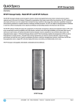
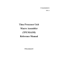
2. Functional Overview
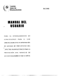
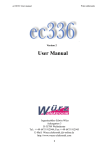
The configuration of the Dual Controller EVB uses a MPC563 master
device connected to a MPC561 slave device. The MPC563 master device
has on chip flash memory that contains the master code and the relocatable slave code. See Figure 1.
For More Information On This Product,
Go to: www.freescale.com
Freescale Semiconductor, Inc.
Slave Reset
Config Word
General IO
Master Reset
Config Word
Data
General IO
Address
Flash
Control
KaPwr
MPC561
Freescale Semiconductor, Inc...
MPC563
ExtClk
I/O
Reset
Gnd
POReset
20MHz
Osc
Gnd
Figure 1
On system boot up the master device boots from its internal flash memory while holding
the slave device in reset. The master device uses the internal flash reset configuration
word (RCW) on system boot.
The master device releases the slave device from reset, which samples the reset
configuration word (RCW) from the external data bus. The RCW is setup via dipswitches on the dual-controller EVB. The RCW is presented to the slave device on the
data bus with use of external logic that monitors the slave poreset and sreset signals.
Refer to Dual MPC561/2/3/4 Autotemp Evaluation Board User’s Manual,
MPC561AEVBUM/D for more detail on the hardware description.
The reset configuration word for the slave places the device in peripheral mode. In
peripheral mode the master has access to the internal memory map of the slave. The
master then configures the slave and loads the re-locatable code into the slave’s
CALRAM.
Dual Controller Software Development for MPC561/MPC563 EVB
For More Information On This Product,
Go to: www.freescale.com
2
Freescale Semiconductor, Inc.
The master releases the slave from peripheral mode into slave mode. The slave then
executes the loaded code. In this configuration the slave does not have access to the
master device.
The master executes it own code from its internal flash memory.
It is the advanced features of the linker that provide the ability to partition and relocate
the code.
3. Detailed Description
3.1. Hardware Configuration
Freescale Semiconductor, Inc...
For a hardware description refer to Multi-controller Hardware Development for MPC5xx
Family, AN2667.
The extclk input on the slave device is connected to the clkout pin of the master device.
The modck[1:3] pins for the slave device are set to 0b100 which selects extclk pin as a
1:1 clock source for the slave. This enables the clock on slave device to synchronise to
the clock on the master device.
Slave Device Configuration
The slave device reads the reset configuration word from the data bus, as the EXTCONF
pin is pulled low.
The reset configuration word sets up the following conditions:
•
Address Map (D28:30 = 0b001): Selects the slave device to reside at address
0x40000- 0x7FFFFF. This is the IMMR[ISB0:2 = 0b001] settings.
•
Peripheral Mode (D16= 0b1): Allows the Master device to access the internal
memory mapped address of the slave.
•
External Arbitration(D0 = 0b1): Allows master device to control bus arbitration.
•
Re-locatable Exception Table: The base address of the slave device is set to
0x400000 (IMMR[ISB0:2]=0b001) and the default location for the exception
table is expected at address 0x400000 through 0x402000. However, the Slave
MPC561 has no internal or external memory mapped to this address to store the
exception table. Therefore the exception table has to be relocated into the slave
internal CALRAM. This is achieved by setting the following bits:
•
IP bit(D1 = 0b1) is required to be set.
•
ETRE bit(D19 = 0b1). Exception Table Relocation Enable is set to enable the
BBCMCR[OERC] bits.
•
OERC bits (D24:25 =0b11). This sets the bits in the BBCMCR which relocates
the Exception Table to the internal CALRAM at address 0x7FE000 for the slave
device. Note that the exception table is a list of branch absolute commands set at
double-word boundaries.
Dual Controller Software Development for MPC561/MPC563 EVB
For More Information On This Product,
Go to: www.freescale.com
3
Freescale Semiconductor, Inc.
Master Device Configuration
The master device uses the internal reset configuration word as UC3FCFG is erased
(0x00000000). This RCW is selected as the active low bit UC3FCFG[HC](RCW:D20) is
erased.
This sets the device to be master with internal memory space, mapped from 0x0000000 0x3FFFFFF (IMMR[ISB0:2] = 0b000) with internal bus arbitration enabled. The
exception table for the master device is at address 0x00000000-0x00002000.
Reference the MPC561/MPC563 User Manual and for a more detailed description of the
reset configuration word.
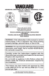
3.2. Single Processor Software
Freescale Semiconductor, Inc...
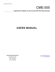
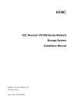
For single processor development the software structure is shown in Figure 2.
Single Processor Software
M563 Memory Map
0x0000 0000
0x0000 0100
ex_tbl.s
Exception table
_start
POReset
0x0000 2000
_start
Init Device
ert0etas.s
m563_setup
Exception Functions
m563_setup.c
main code
ex_tbl_func.c
Exception Functions
main.c
Main Code
m563.h
Const/Initialised Var
Unused Flash
0x0007 FFFF
Memory
Mapped
Registers
0x003F 8000
M563_common.h
file
FLASH
m563_<Module.h>
Files
Variables
CALRAM
0x003F FFFF
Figure 2
Dual Controller Software Development for MPC561/MPC563 EVB
For More Information On This Product,
Go to: www.freescale.com
4
Freescale Semiconductor, Inc.
Header Files
The header files contain definitions for registers defined within the device for each
module and are combined into a single device header file mpc563.h. These are defined as
structures that allow register, bit-group or bit-wise access. There is an additional
m563_common.h header file that holds global module definitions.
crt0.s
The crt0.s file is an assembler file that initialises the device.
The function _start is defined as the address to run at boot-up, which is called from the
reset vector by the branch absolute _start instruction.
The following diagram show the startup and termination control of the crt0.s file.
Crt0etas.s
Initialise .sdata/.sdata2 base address
User’s Init Program
Freescale Semiconductor, Inc...
_start:
Call setup_mpc563()
…
void
setup_mpc563()
{
…
return();
}
This file performs the standard DIAB crt0 actions. It is important to understand the
sequence for the single processor as this file needs to be modified for the dual processor
software. The following describes the operations in this file:
1.
2.
3.
Initialize stack: Loads Register1 with the Stack Pointer
Loads Register13 with the SDA (Small Data Area) base address.
Global or static variables are accessed relative to the base address with a
16bit offset.
Loads Register2 with the SDA2 (Small Const Area) base address. Constant
initialised/uninitialised variables are accessed relative to the base address
with a 16bit offset.
Dual Controller Software Development for MPC561/MPC563 EVB
For More Information On This Product,
Go to: www.freescale.com
5
Freescale Semiconductor, Inc.
4.
5.
Calls the setup_mpc563 function in mpc563.c, which configures the device.
The file then calls __init_main function to initialize local variables which
then calls the users main() function. The main function in the demo code
never returns.
mpc563.c
The setup_mpc563 function call from the crt0.s file configures the device:
1. Disables the watchdog timer.
2. Sets the system clock frequency to 56MHz.
3. Disables the time base decrementor hardware.
4. Sets the IMB bus to run at full system clock frequency.
5. And finally configures the core special purpose registers.
Freescale Semiconductor, Inc...
Note
If you only use MPC563 internal flash memory as storage
you should not enable BBC burst in the dual processor
system. A master cannot burst internally when connected to
a slave device.
ex_tbl.s and ex_funcs.c
The assembler file ex_tbl.s uses the .org command to setup function calls for the
exception table at 0x100 byte intervals. The NMI/Reset (System Boot) function at
address location 0x100 calls the _start function. The branch instructions for all other
interrupts are defined in the ex_funcs.c file.
The exception functions in the ex_funcs.c file places the device into an endless loop
should an exception occur. This allows exceptions to be trapped. Alternatively the user
may define their exception handler functions in this file.
main.c
The main.c file contains the main code for the processor to run. The main code is the top
level user specific code.
makefile
This file defines the files to be compiled, assembled and linked to generate a .ELF file
that can be downloaded into FLASH memory.
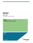
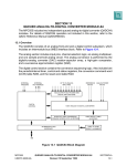
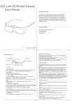
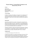
3.3. Dual Processor Software
For the dual processor configuration the master device stores the software in an unused
area of flash that is relocated to the slave device during execution initialisation. This is
shown in Figure 3.
Dual Controller Software Development for MPC561/MPC563 EVB
For More Information On This Product,
Go to: www.freescale.com
6
M 5 6 3 _co m m o n .h
f ile
m 5 63 _ < M od u le.h >
Files
m 5 6 3 .h
0 x 00 0 0 7 00 0
FL A S H
0 x 00 0 0 2 00 0
0 x 00 0 0 0 00 0
0 x 00 0 0 0 10 0
For More Information On This Product,
Go to: www.freescale.com
0 x 00 3 F F F F F
0 x 00 3 F 80 0 0
M e m o ry 0 x 00 0 7 F F F F
M a p p ed
R e g is te rs
S t a rt S la v e D e v ic e
m ain .c
ex _ tb l_ f un c. c
E x ceptio n Fu n ctio ns
In i t S la v e C od e
m 56 3 _ setup . c
er t0 etas .s
ex _ tb l.s
E x cep tio n tab le
D u a l P ro c e s so r S o ftw a re
Figure 3
C AL RA M
V a ri a bl e s
U nu s ed F l a sh
S la v e C o de
U nu s ed F l a sh
C o ns t/ Ini ti a l is e d V a r
m a in c od e
Ex c e pt io n Fu n c ti on s
m 56 3_ se t up
_ st a rt
In i t D e vi c e
_ st a rt
E xc e p ti on T a bl e
P O Res et
M 5 6 3 M e m o r y M ap
ct ea
t
e
0 x 00 7 F F F F F
0 x 00 7 F e 00 0
Re
Rl o
ecl
oa
R e lo c a te
R e loc a te
0 x 00 0 7 F 8 0 0
Sl a v e
M e m o ry
M apped
R e g i ste rs
0 x 00 0 7 F F F F
E xc e p ti on T a bl e
_s ta rt
C AL RA M
C o ns t/ Ini ti a li s e d V a r
V a ri a bl e s
m a in c o d e
Ex c e pt io n Fu n c ti on s
_s ta rt
In i t D e vi c e
m 56 1_ se t up
N o Ex te rn a l M e m ory
M 5 6 1 M e m o ry M a p
0 x 00 0 0 0 00 0
Freescale Semiconductor, Inc...
E n te r
S la ve
M ode
Freescale Semiconductor, Inc.
Freescale Semiconductor, Inc.
m563_common.h
The base address for slave device is defined in the m563_common.h header file:
#ifndef
#define
#endif
#ifndef
#define
#endif
INTERNAL_MEMORY_BASE
INTERNAL_MEMORY_BASE 0x00000000
SLAVE_INTERNAL_MEMORY_BASE
SLAVE_INTERNAL_MEMORY_BASE 0x00400000
The RCW base address (IMMR[ISB0:2]) for both the master and slave MUST match the
address defined in the m563_common.h file.
Freescale Semiconductor, Inc...
The header files were modified to define the slave hardware registers in addition to the
master hardware registers. An examples is shown for definition of the slave UISU
module:
struct USIU_tag *USIU = (struct USIU_tag *) (INTERNAL_MEMORY_BASE + 0x2FC000);
struct USIU_tag *SLAVE_USIU = (struct USIU_tag *) (SLAVE_INTERNAL_MEMORY_BASE +
0x2FC000));
crt0.s
The crt0.s file for the dual controller is the same as for the single processor, except that
the function setup_mpc563 has been renamed to setup_master. And the file containing
this function has been renamed from mpc563.c to setup_master.c file.
setup_master.c
This file is the same as the mpc563.c for the single processor development with some
extended functions detailed below.
In the dual processor application the master device also configures the slave device with
memory-mapped accesses. In addition to setting up the master device the code also
performs the following:
1.
2.
3.
4.
Configures Master IO for Slave Reset control.
Waits for the master PLL to lock on set frequency.
Disables the slave device watchdog timer.
Sets up TSIZE to be driven by external data bus. Master/Slave mode
requirement.
5. Retry function enabled. When an external master owns the bus and the
internal bus on the slave initiates access to the external bus at the same time as
the master, this signal is used to cause the external master to relinquish the bus
for one clock to solve the contention. This is a Master/Slave mode
requirement.
6. Sets IMB bus to run at system frequency as default is half the system
frequency.
The following operations relocate code from the master internal FLASH memory to the
slave CALRAM. The master internal FLASH memory address location and size and the
slave CALRAM address are provided by user define variables defined in the linker file.
7. Copies the exception table to the slave CALRAM at
-8-
Dual Controller Software Development for MPC561/MPC563 EVB
For More Information On This Product,
Go to: www.freescale.com
8
Freescale Semiconductor, Inc.
8. Copies the code to the slave CALRAM at address 0x07F8000.
9. Copies the data section to the slave CALRAM following the Code section.
This contains DATA, CONST and STRING data types.
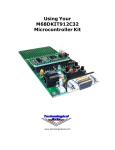
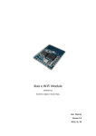
main.c
The main.c file contains the code to start the slave processor running.
The additional files required for the dual controller are depicted in Figure 4.
M561 Memory Map
Dual Processor Software
Freescale Semiconductor, Inc...
M563_common.h
file
0x0000 0000
m563_<Module.h>
Files
No External Memory
0x0007 FFFF
Slave
Memory
Mapped
Registers
m563.h
start_slave.s
.section “.text_slave”,,c
0x0007 F800
_start
Init Device
m561_setup
setup_slave.c
Exception Functions
ex_tbl_func_slave.c
Exception Functions
main code
Const/Initialised Var
Variables
main_slave.c
CALRAM
slave.h
ex_tbl_slave.s
Exception table
0x007F e000
Enter
Slave
Mode
_start
Exception Table
.section “.text_slave”,,c
0x007F FFFF
Figure 4
Dual Controller Software Development for MPC561/MPC563 EVB
For More Information On This Product,
Go to: www.freescale.com
9
Freescale Semiconductor, Inc.
slave.h
The slave.h file contains linker information that is used to partition the slave and master
software. The default complier sections names are used to define sections for the master
device and the user defines section names are used to define sections for the slave device
Freescale Semiconductor, Inc...
Section
Description
Section Names
Default
User Defined
CODE
code generated in functions
.text
.test_slave
DATA
static and global variables size in bytes > Xsmall-data:
.data
.data_slave
SDATA
Variables, size in bytes <= -Xsmall-data:
.sdata/.sbss
.sdata_slave/
.sbbs_slave
CONST
const variables, size in bytes > -Xsmall-const:
.text
.text_slave
SCONST
const variables, size in bytes <= -Xsmall-const:
.sdata2
.sdata2_slave
STRING
string constants:
.text
.text_slave
Figure 5
The slave.h file is included into all .c files that are specific to the slave device. These files
use pragma statements to section the code:
#pragma
#pragma
#pragma
#pragma
#pragma
#pragma
section
section
section
section
section
section
CODE
DATA
SDATA
CONST
SCONST
STRING
".text_slave"
".data_slave"
".sdata_slave" ".sbss_slave"
".text_slave" ".text_slave"
".sdata2_slave" ".sdata2_slave"
".data_slave"
Refer to Figure 5 and the Diab Users’ Manual for further information.
The slave .s assembler files were modified directly with an explicit section command:
.section “.text_slave”,,c
There is an option in linker to generate and combine sections together by using file
names. However individual files have to be specified in the linker file as no method exists
to use “wild-star” characters to identify files by type.
start_slave.c
The slave device does not use a crt0.s file. The slave device uses a file called
start_slave.c. This file contains the _start_slave routine. This is the routine, called from
the reset vector, to run the slave at boot-up.
Dual Controller Software Development for MPC561/MPC563 EVB
For More Information On This Product,
Go to: www.freescale.com
10
Freescale Semiconductor, Inc.
Freescale Semiconductor, Inc...
This file:
1. Loads Register1 with the Slave Stack Pointer.
2. Loads Register13 with the Slave SDA (Small Data Area) base address. Global
or static variables are accessed relative to the base address with a 16bit offset.
The base address is calculated by adding 0x7FF0 to the slave address of the
small data area which is provided by the dual.dld linker file.
This 0x7FF0 offset permits any variable in either section to accessed with a
single instruction using a 16-bit offset from the r13 register. Note that this
limits the combined size of the two sections to 64KB - 0x10 (the 0x10
facilitates certain optimizations). Refer to the Diab Tools Suite Users’ Manual
for more information.
3. Loads Register2 with the Slave SDA2 (Small Const Area) base address.
Constant initialised/uninitialised variables are accessed relative to the base
address with a 16bit offset. The base address is calculated by adding 0x7FF0
to the slave address of the small data area which is provided by the dual.dld
linker file.
4. The file then calls the setup_slave function in setup_slave.c, which configures
the device special purpose registers, non memory-mapped functions, which
need to be executed by the slave.
5. Calls the main_slave function. The main_slave function in our demo code
never returns.
setup_slave.c
Not all the setups required for the slave are memory mapped. The special purpose
registers in the core need to be setup from the slave itself. This function is called during
the slave startup.
ex_tbl_slave.s
This file contains the re-locatable exception table. This assembler file contains the branch
absolute commands to the functions defined in ex_funcs_slave.c and the _start_slave
function defined in the start_slave.c file.
This file was generated using an “.align 3” assembler directive to ensure an 8byte
boundary for the branch calls. (Compressed code can use all 8bytes as instructions can be
> 4bytes). This code can then be directly copied into the relocated exception table in the
slave CALRAM at 0x7FE000. An alternative method would be to use the .word
command to align the vector branch instructions.
NOTE
The use of the .org statement cannot be used to generate the
vector table because the code has to be re-locatable.
ex_funcs_slave.c
The example exception functions in the ex_funcs_slave.c file place the device into an
endless loop should an undefined exception occur in the slave device. The loop allows
exception to be trapped. Alternatively the user may define their exception handler
functions in this file.
Dual Controller Software Development for MPC561/MPC563 EVB
For More Information On This Product,
Go to: www.freescale.com
11
Freescale Semiconductor, Inc.
main_slave.c
The main_slave.c file contains the main code for the processor to run.
The makefile
This file defines the files to be compiled, assembled and linked to generate a .ELF file
that can be downloaded into FLASH.
3.4. Dual Processor Software Compiler Options
Freescale Semiconductor, Inc...
The dual processor code is compiled with the following additional options:
•
-Xpragma-section-last
Normally the pragma section returns to the default section when a definition or
declaration is seen in the compiled code. Setting the option -Xpragma-section-last
allows prototype definitions or declarations within the *.c code, without reverting
to the default pragma section. This allows the use of the “pragma section”
statements to be defined once in the slave.h header file. Including this header into
any slave code *.c file will automatically define to code in the slave section for
the linker. Refer to Diab 4.4b release note for further information and slave.h
description.
•
-Xcode-relative-far-all
Required for short variable definitions that are out-with the 64K offset boundary.
This is used for variables that are relocated in the slave device which has a
0x400000 base address offset.
3.5. Dual Processor Linker File
The linker file, dual.dld, is used to generate the .ELF file by placing code and data into
the appropriate memory mapped locations for both the master and the slave and resolving
all addressing.
The linker file defines the memory map areas area:
MEMORY
{
rom_vtbl:
rom:
org = 0x000000, len = 0x2000
org = 0x002000, len = 0x5000
/* Master Vector Table */
/* Master Flash - Master Code
ram:
stack:
rom2:
org = 0x3f8000, len = 0x2000
org = 0x3fa000, len = 0x5000
org = 0x007000, len = 0x5000
/* Master RAM */
/* Master Stack */
/* Master Flash - Slave Code
ram_vtbl_slave:
ram_slave:
stack_slave:
org = 0x7fe000, len = 0x2000
org = 0x7f8000, len = 0x4000
org = 0x7fc000, len = 0x2000
/* Slave Vector Table */
/* Slave RAM */
/* Slave Stack */
*/
*/
}
The linker file then extracts all slave code from the object files of the types defined with
the section definitions. All default section code is considered to be master code.
The memory map in Figure 6 shows where the code sections will be located and user
defined memory pointers.
Dual Controller Software Development for MPC561/MPC563 EVB
For More Information On This Product,
Go to: www.freescale.com
12
Freescale Semiconductor, Inc.
Freescale Semiconductor, Inc...
/* This block specifies where and how the linker should locate different
* modules of the system.
*
* This example will allocate according to the following map:
*
* 0x0:
+-------------------------------+
*
| Exception Routines
|
* 0x2000
+-------------------------------+
* "rom"
| Program code(1)
|
*
| (2)
|
*
+-------------------------------+ <- __DATA_ROM
*
| ROM Image of initialized data |
*
| (3)
|
*
+-------------------------------+
*
| (Unused portion of "rom")
|
* 0x7000
+-------------------------------+ <- __VTBL_ROM_SLAVE
* "rom2"
| Slave Exception Routines
|
*
+-------------------------------+ <- __CODE_ROM_SLAVE
*
| Slave Program code
|
*
|
|
*
+-------------------------------+
*
| ROM Image of Constants
|
*
+-------------------------------+ <- __DATA_ROM_SLAVE
*
| ROM Image of initialized
|
*
| Slave data
|
*
+-------------------------------+
*
| (Unused portion of "rom")
|
*
+-------------------------------+
*
*
Gap -- Not used
*
* 0x3f8000:
+-------------------------------+ <- __DATA_RAM
* "ram"
| Memory reserved for
|
*
| initialized data
|
*
+-------------------------------+ <- __DATA_END, __BSS_START
*
| Uninitialized data
|
*
|
|
*
+-------------------------------+ <- __BSS_END, __HEAP_START
*
| Memory reserved for the heap |
*
| (all unused "ram")
|
* 0x3fa000:
+-------------------------------+ <- __HEAP_END (3) & __SP_END (3)
* "stack"
| Memory reserved for the stack |
*
| (all of the "stack")
|
* 0x400000:
+-------------------------------+ <- __SP_INIT
*
*
*************************************************************************************
* SLAVE DEVICE
*************************************************************************************
* 0x7f8000
+-------------------------------+ <- __CODE_START_SLAVE
* "ram"
| Slave Program code
|
*
|
|
*
+-------------------------------+ <- __CODE_END_SLAVE,__DATA_RAM_SLAVE
*
| Memory reserved for
|
*
| initialized data
|
*
+-------------------------------+ <- __DATA_END_SLAVE, __BSS_START_SLAVE
*
| Uninitialized data
|
*
|
|
*
+-------------------------------+ <- __BSS_END_SLAVE, __HEAP_START_SLAVE
*
| Memory reserved for the heap |
*
| (all unused "ram")
|
* 0x3fa000:
+-------------------------------+ <- __HEAP_END_SLAVE, __SP_END_SLAVE
* "stack"
| Memory reserved for the stack |
*
| (all of the "stack")
|
* 0x3fe000:
+-------------------------------+ <- __SP_INIT_SLAVE,VTBL_START_SLAVE
*
| Relocated Vector Table
|
* 0x400000:
+-------------------------------+ <- VTBL_END_SLAVE
*************************************************************************************
Figure 6
Dual Controller Software Development for MPC561/MPC563 EVB
For More Information On This Product,
Go to: www.freescale.com
13
Freescale Semiconductor, Inc.
The linker file uses the LOAD command to place all the slave sections into the virtual
memory of the slave device. This is shown in Figure 6.
The slave vector table is stored in to the internal flash memory of the master device at
address 0x7000(rom2) and loaded into the virtual (run time) address 0x7FE000
(ram_vtbl_slave) of the slave CALRAM.
.text_vtbl_slave (TEXT) LOAD(ADDR(rom2)) :
{ ex_tbl_slave.o(.text_slave) } > ram_vtbl_slave
Freescale Semiconductor, Inc...
The CODE and DATA sections are stored in the master device internal flash memory
following the slave vector table and loaded into the virtual(run time) address 0x7F8000
(ram_slave) of the slave CALRAM. The syntax *(.<type>) identifies all files in the
current directory where the code <type> matches. The data types are defined in Figure 5.
GROUP : {
.text_slave (TEXT) LOAD(ADDR(rom2)+SIZEOF(.text_vtbl_slave)):
{
*(.text_slave)
}
These link commands select the CODE section at the rom2(slave code) address in the
master device offset by the size of the VECTOR TABLE. Refer to block description
above.
.sdata2_slave (TEXT) LOAD(ADDR(.text_slave)+SIZEOF(.text_slave)):
{
*(.sdata2_slave)
}
These link commands select the SCONT section at the rom2(slave code) address in the
master device offset by the size of the VECTOR TABLE and CODE.
/* This will reserve space for the .data in the beginning
* of "ram" but actually place the image at the end of
* .text segment
*/
.data_slave (DATA) LOAD(ADDR(.sdata2_slave)+SIZEOF(.sdata2_slave)) :
{
*(.data_slave)
}
These link commands select the DATA section at the rom2(slave code) address in the
master device offset by the size of the VECTOR TABLE, CODE and SCONT.
/* .sdata contains small address data */
.sdata_slave (DATA) LOAD(ADDR(.data_slave)+SIZEOF(.data_slave)) :
{
*(.sdata_slave)
}
Dual Controller Software Development for MPC561/MPC563 EVB
For More Information On This Product,
Go to: www.freescale.com
14
Freescale Semiconductor, Inc.
These link commands select the .SDATA section at the rom2(slave code) address in the
master device offset by the size of the VECTOR TABLE, CODE, SCONT and DATA
/* This will allocate the .bss symbols */
/* LOAD command not need for un-initialised
variables codes initialises RAM to 0x00 */
.sbss_slave (BSS)
:
{
*(.sbss_slave)
}
.bss_slave (BSS)
:
{
*(.bss_slave)
}
These link commands select the .SBSS and .BSS un-initialised variables section at the
rom2(slave code) address in the master device offset by the size of the VECTOR
TABLE, CODE, SCONT, DATA and SDATA.
/* Any space left over will be used as a heap */
} > ram_slave
Freescale Semiconductor, Inc...
Place all CODE and DATA identified above into the virtual address of the slave
CALRAM defined by ram_slave.
The remaining sections defined in the object files are placed into the master device.
GROUP : {
.text (TEXT)
:
*(.text)
}
/* Next take all
.sdata2 (TEXT) :
} > rom
{
*(.rodata) *(.rdata) *(.init) *(.fini)
small CONST data */
{}
/* The second section will allocate space for the initialized data
* (.data/.sdata) and the unititialized data (.bss/.sbss) in the "ram" section.
*
* Initialized data is actually put at the end of the .text section
* with the LOAD command. The function __init_main() moves the
* initialized data from ROM to RAM.
*/
GROUP : {
/* This will reserve space for the .data in the beginning
* of "ram" but actually place the image at the end of
* .text segment
*/
.data (DATA) LOAD(ADDR(.sdata2)+SIZEOF(.sdata2)) : {}
/* .sdata contains small address data */
.sdata (DATA) LOAD(ADDR(.sdata2)+SIZEOF(.sdata2)+SIZEOF(.data)) : {}
/* This will allocate the .bss symbols */
.sbss (BSS)
: {}
.bss (BSS)
: {}
/* Any space left over will be used as a heap */
} >ram
The linker also sets up memory pointers based on the size and location of the sections.
These pointers are used in the object files to setup:
1.
2.
3.
4.
Master and Slave Stack Pointers
Base Address Locations for Slave short data sections
Slave relocation routines for code, data and Exception Table.
Library Functions
Common functions MUST be defined ONLY once for the dual processor application,
otherwise the complier generates a function redefinition error.
To resolve this on the dual controller board the hardware needs to be configured to allow
both processors to access the same executable code. In the current configuration the
Master device can access the internal address space of the Slave device however the
Dual Controller Software Development for MPC561/MPC563 EVB
For More Information On This Product,
Go to: www.freescale.com
15
Freescale Semiconductor, Inc.
Slave device has no access to the internal address space of the Master device as this is
configured for master mode.
Configuring the Master device in a slave configuration allows the Slave device to access
the internal address space of the Master device.
This method is very inefficient from a performance point of view. For performance
critical functions separate functions should be defined for the slave and master device.
Refer to Section 7 of Multi-controller Hardware Development for MPC5xx Family,
AN2667.
Freescale Semiconductor, Inc...
This is accomplished by setting SLVM bit in the EMCR register from the Master device
code.
//******************************************************************************
// Function
: master_to_slave_mode
// Description : switches MASTER Device from MSTR to SLVM mode.
// Parameters
: none
// Returns
: none
// ******************************************************************************
void master_to_slave_mode()
{
USIU.EMCR.B.SLVM = 0x1;
}
In addition to configuring the Master device to slave mode, the BDIS bit is also set to
ensure the memory controller on the slave device is not active after reset. This is
accomplished by setting the DBIS bit on the data bus reset configuration word (RCW)
(D4 = 0x1).
Slave inter communication with the master does NOT require chip select. On system boot
the slave code is run from its internal CALRAM.
The example code was modified to use the Slave device to call an external function
defined in the internal flash memory of the master device. This function was used switch
an LED on and off by accessing the master PortQA pin PQA7.
This function subsequently called an external function on the slave to delay the turn onoff time of the LED.
The Slave device used a similar function to call its own local function to flash the slave
LED on PortQA pin PQA7.
Slave Code:
External definition:
// *** External function prototype definitions *************************
extern void flash_master_led();
Slave device main function:
void main_slave(void)
{
// Function to Flash Slave LED
SLAVE_QADC_A.DDRQA.B.DDQA7 = 1;
/* setup QADC A port A7 as output */
while(1){
SLAVE_QADC_A.PORTQA.B.PQA7 = 0;
delay(100);
SLAVE_QADC_A.PORTQA.B.PQA7 = 1;
delay(100);
flash_master_led();
}
}
Dual Controller Software Development for MPC561/MPC563 EVB
For More Information On This Product,
Go to: www.freescale.com
16
Freescale Semiconductor, Inc.
Master Code:
External definition:
// *** External function prototype definitions *************************
extern void delay(UINT8);
Master Device function:
Freescale Semiconductor, Inc...
void flash_master_led()
{
// Function to Flash Slave LED
QADC_A.DDRQA.B.DDQA7 = 1;
/* setup QADC A port A7 as output */
QADC_A.PORTQA.B.PQA7 = 0;
delay(100);
QADC_A.PORTQA.B.PQA7 = 1;
delay(100);
}
5.
Limitations
The Diab compiler/linker used for the code compilation has a limitation with global
variable assignments definitions for the slave device. The compiler/linker allocates
memory location but does not initialize the contents.
That is,
// *** Global Variable Definition ***********************************
UINT32 delay_value = 0x0007FFFF;
The work around for global variables assignments is to assign the global variable at run
time.
That is,
// *** Global Variable Definition ***********************************
UINT32 delay_value;
void init_gvars(void)
{
delay_value = 0x0007FFFF;
}
Local function global variables assignments are not affected.
6.
Conclusion
This application note demonstrates one method in developing code for a dual master and
slave device using the linker to relocate the code from the master device to the slave
device. This method allows simple generation of dual processor code that shares common
library functions. For increased performance common functions can be defined by the
user for each processor. The proposed method minimises code depth but with
performance trade offs.
Alternative methods are available that include writing separate code for the master and
slave. A runtime loader would need to be developed for the master device to relocate a
separately generated s-record into the slave at startup. This method would minimise interprocessor communication but maximise code size.
Dual Controller Software Development for MPC561/MPC563 EVB
For More Information On This Product,
Go to: www.freescale.com
17
Freescale Semiconductor, Inc.
Freescale Semiconductor, Inc...
THIS PAGE INTENTIONALLY LEFT BLANK
Dual Controller Software Development for MPC561/MPC563 EVB
For More Information On This Product,
Go to: www.freescale.com
18
Freescale Semiconductor, Inc.
Freescale Semiconductor, Inc...
THIS PAGE INTENTIONALLY LEFT BLANK
Dual Controller Software Development for MPC561/MPC563 EVB
For More Information On This Product,
Go to: www.freescale.com
19
Freescale Semiconductor, Inc.
HOW TO REACH US:
USA / EUROPE / Locations Not Listed:
Freescale Semiconductor, Inc...
Motorola Literature Distribution
P.O. Box 5405
Denver, Colorado 80217
1-800-521-6274 or 480-768-2130
JAPAN:
Home Page:
www.freescale.comMotorola Japan Ltd.
email:
SPS, Technical Information Center
[email protected]
3-20-1, Minami-Azabu Minato-ku
USA/Europe or Locations
Not Listed:
Tokyo, 106-8573
Japan
Freescale Semiconductor
81-3-3440-3569
Technical Information Center, CH370
ASIA/PACIFIC:
1300 N. Alma School Road
Motorola Semiconductors H.K. Ltd.
Chandler, Arizona 85224
Silicon Harbour Centre
(800) 521-6274
2 Dai King Street
480-768-2130
Tai Po Industrial Estate
[email protected]
Tai and
Po, N.T.,
Hong Kong
Europe, Middle East,
Africa:
Freescale Halbleiter852-26668334
Deutschland GmbH
Technical Information
Center
HOME
PAGE:
Schatzbogen 7
http://motorola.com/semiconductors
81829 Muenchen, Germany
+44 1296 380 456 (English)
+46 8 52200080 (English)
+49 89 92103 559 (German)
+33 1 69 35 48 48 (French)
[email protected]
Japan:
Freescale Semiconductor Japan Ltd.
Headquarters
ARCO Tower 15F
Information in this document is provided solely to enable system and software
1-8-1, Shimo-Meguro, Meguro-ku
implementers to use Freescale Semiconductor products. There are no express or
Tokyo 153-0064, Japan
implied copyright licenses granted hereunder to design or fabricate any integrated
0120 191014
circuits or integrated circuits based on the information in this document.
+81 2666 8080
Freescale Semiconductor reserves the right to make changes without further notice to
any products herein. Freescale Semiconductor makes no warranty, representation or
[email protected]
Information
in
this
document
is
provided
solely
to enable
system and
to use
guarantee
regarding
the suitability
of itssoftware
productsimplementers
for any particular
purpose, nor does
Asia/Pacific:
Motorola products. There are no express
or implied
copyright
licenses
or
Freescale
Semiconductor
assume
anygranted
liability hereunder
arising out to
of design
the application
or use of
Freescale Semiconductor
Hong
Kong
Ltd.
fabricate any integrated circuits or integrated
circuits
based
on
the
information
in
this
document.
any product or circuit, and specifically disclaims any and all liability, including without
Technical Information Motorola
Center reserves the right to make
changes
without
further
notice
to
any
products
herein.
Motorola
limitation consequential or incidental damages. “Typical” parameters which may be
2 Dai King Street
makes no warranty, representation
or guarantee
regarding
the suitability
of its and/or
products
for any can and do
provided
in Freescale
Semiconductor
data sheets
specifications
Tai Po Industrial Estate,
particular purpose, nor does Motorola
anyapplications
liability arising
of performance
the application
or vary
use of
any
vary assume
in different
and out
actual
may
over
time. All operating
product or circuit, and specifically
disclaims
any and
all liability,
without
limitation application by
Tai Po, N.T., Hong Kong
parameters,
including
“Typicals”
must beincluding
validated for
each customer
consequential
or
incidental
damages.
“Typical”
parameters
which
may
be
provided
in
Motorola
data
customer’s technical experts. Freescale Semiconductor does not convey any license
+800 2666 8080
sheets and/or specifications can and
do vary
in different
applications
actual Freescale
performance
may vary products are
under
its patent
rights nor
the rightsand
of others.
Semiconductor
[email protected]
over time. All operating parameters,
includingintended,
“Typicals”
must be for
validated
for each customer
not
designed,
or
authorized
use
as
components
in systems intended for
For Literature Requests
Only:
application by customer’s technical
experts.
Motorola
does
notorconvey
any licenseintended
under itsto patent
surgical
implant
into the
body,
other applications
support or sustain life,
Freescale Semiconductor
rights nor the rights of others. Motorola
products
not designed,
intended,
or of
authorized
for use
as
or for any
other are
application
in which
the failure
the Freescale
Semiconductor
product
Literature Distribution components
Center
in systems intended for
surgical
intowhere
the body,
or other
intended
to
could
createimplant
a situation
personal
injuryapplications
or death may
occur. Should
Buyer
P.O. Box 5405
support or sustain life, or for any purchase
other application
in which Semiconductor
the failure of the
Motorola
or use Freescale
products
for product
any suchcould
unintended or
create a situation where personal unauthorized
injury or death
may occur.
Should
purchase
or use
Motorola
Denver, Colorado 80217
application,
Buyer
shallBuyer
indemnify
and hold
Freescale
Semiconductor
products for any such unintended or
unauthorized
application, subsidiaries,
Buyer shall indemnify
hold Motorola
and
its officers, employees,
affiliates, and distributors
harmless against all
(800) 441-2447
and its officers, employees, subsidiaries,
and distributors
harmless
all claims,
costs,
claims, affiliates,
costs, damages,
and expenses,
and against
reasonable
attorney
fees arising out of,
303-675-2140
damages, and expenses, and reasonable
feesany
arising
out
directlyinjury
or indirectly,
claim ofwith such
directly attorney
or indirectly,
claim
of of,
personal
or deathany
associated
Fax: 303-675-2150 personal injury or death associated
with such
unintended oruse,
unauthorized
even
if such
claim
unintended
or unauthorized
even if suchuse,
claim
alleges
that Freescale
LDCForFreescaleSemiconductor
alleges that Motorola was negligentSemiconductor
regarding the design
or manufacture
of the
the design
part. or manufacture of the part.
was negligent
regarding
@hibbertgroup.com MOTOROLA and the Stylized M Logo are registered in the U.S. Patent and Trademark Office. The
described product contains a PowerPC processor core. The PowerPC name is a trademark of IBM
Corp. and used under license. The described product is a PowerPC microprocessor. The PowerPC
name is a trademark of IBM Corp. and used under license. The described product is a PowerPC
microprocessor core. The PowerPC name is a trademark of IBM Corp. and is used under license. The
PowerPC name is a trademark of IBM Corp. and is used under license. All other product or service
names are the property of their respective owners. Motorola, Inc. is an Equal Opportunity/Affirmative
Action Employer.
© Motorola, Inc. 2004
Dual Controller Software Development for MPC561/MPC563 EVB
For More Information On This Product,
Go to: www.freescale.com
20