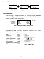
1
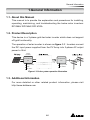
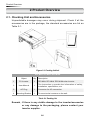
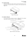
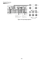
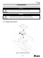
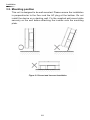
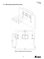
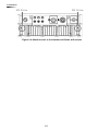
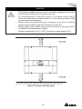
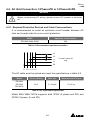
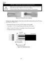
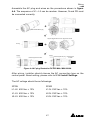
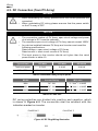
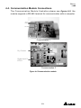
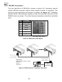
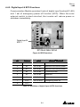
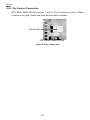
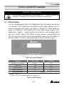
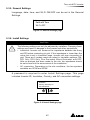
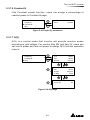
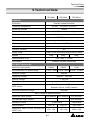
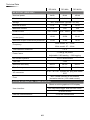
The power behind competitiveness
Grid-tie Transfomerless Solar Inverter
RPI M6A / M8A / M10A Operation and Installation Manual
www.deltaww.com
Contents
1. General Information --------------------------------------------------------------5
1.1. About this Manual ------------------------------------------------------------ 5
1.2. Product Description ---------------------------------------------------------- 5
1.3. Additional Information ------------------------------------------------------- 5
2. Product Overview -----------------------------------------------------------------6
2.1. Checking Unit and Accessories ------------------------------------------- 6
2.2. Product Label ------------------------------------------------------------------ 7
2.3. Exterior Objects --------------------------------------------------------------- 7
3. Installation --------------------------------------------------------------------------9
3.1. Unpack the Inverter ---------------------------------------------------------- 9
3.2. Mounting position ------------------------------------------------------------10
3.3. Mounting Dimension -------------------------------------------------------- 11
4. Wiring
--------------------------------------------------------------------------- 14
4.1. Preparation before Wiring -------------------------------------------------14
4.2. AC Grid Connection: 3-Phase+PE or 3-Phase+N+PE -------------15
4.2.1. Required Protective Devices and Cable Cross-sections -15
4.3. DC Connection (from PV Array) -----------------------------------------18
4.4. Communication Module Connections ----------------------------------19
4.4.1. RS-485 Connection ------------------------------------------------20
4.4.2. Digital Input & EPO Functions ----------------------------------21
4.4.3. Dry Contact Connection ------------------------------------------22
5. Turn on/off PV inverter -------------------------------------------------------- 23
5.1. First startup -------------------------------------------------------------------23
5.2. Home Page -------------------------------------------------------------------24
5.3. LCD Flow Chart --------------------------------------------------------------24
5.3.1. Power Meter ---------------------------------------------------------25
5.3.2. Energy Log -----------------------------------------------------------25
5.3.3. Event Log -------------------------------------------------------------26
5.3.4. Inverter Information ------------------------------------------------26
5.3.5. General Settings ----------------------------------------------------27
5.3.6. Install Settings -------------------------------------------------------27
5.3.7. Active/Reactive power---------------------------------------------28
5.3.8. FRT (Fault ride through) ------------------------------------------32
6. Maintenance ---------------------------------------------------------------------- 33
7. Error message and Trouble Shooting ----------------------------------- 34
8. De-Commissioning ------------------------------------------------------------- 40
9. Technical Data ------------------------------------------------------------------- 41
03
Safety Instructions
This manual uses the following instructions for conveying important safety related
information.
CAUTION !
Machine and equipment damage may occur if this hazardous situation is
not avoided.
WARNING !
Death and serious injury may occur if this hazardous situation is not
avoided.
Repair work on the device should ONLY be carried out by the
manufacturer. No user serviceable parts inside.
In Australia, installation and maintenance work shall be conducted by
qualified electrician and shall comply with Australian Regulations.
DANGER !
To avoid risk of electrical shock, do not open the solar inverter. Death
and serious injury will occur if this hazardous situation is not avoided.
WARNING ! BURN HAZARD
The unit may reach very high temperatures and the device surface can
become quite hot. Sufficient cooling time is necessary for optimal yield.
04
General Information
1.General Information
1.1. About this Manual
This manual is to provide the explanation and procedures for installing,
operating, maintaining, and troubleshooting the below solar inverters:
RPI M6A/ RPI M8A/ RPI M10A
1.2. Product Description
This device is a 3-phase grid-tied solar inverter which does not support
off-grid functionality.
The operation of solar inverter is shown as figure 1-1 . Inverters convert
the DC input power supplied from the PV Array into 3-phase AC output
power to Grid.
Install if
necessary
DC Distribution
box
AC Distribution
box
3 phase,
N, PE
Surge arrestor
Surge arrestor
Fuse
AC breaker
DC switch
Figure 1-1 Solar system operation illustration
1.3. Additional Information
For more detailed or other related product information, please visit
http://www.deltaww.com
05
Product Overview
2.Product Overview
2.1. Checking Unit and Accessories
Unpredictable damages may occur during shipment. Check if all the
accessories are in the package, the standard accessories are list as
Table 2-1:
Figure 2-1 Packing listUnit
RPI M6A/ RPI M8A/ RPI M10A
Object
Qty
Description
1
PV Inverter
1
RPI M6A/ RPI M8A/ RPI M10A solar inverter
2
User Manual
1
The Instruction to provide the information of safety,
Installation, specification, etc.
3
AC Plug
1
Connector for AC connection
4
Mounting Bracket
1
To mount solar inverters on the wall.
Table 2-1 Packing list
Remark;If there is any visible damage to the inverter/accesories
or any damage to the packaging, please contact your
inverter supplier.
06
Product Overview
2.2. Product Label
Users can identify the model number and the specifications by the
information on the product label. The location for the label please sees
Figure 2-2.
RPI M6A/ M8A/ M10A
Figure 2-2 Product label
2.3. Exterior Objects
The Inverter's exterior objects are shown in Figure 2-3. The detailed
input/output interfaces illustration is shown in Figure 2-4.
RPI M6A/ M8A/ M10A
AC/DC Switch
LCD/LED Display
and Buttons
DC Connectors
Communication Connection 1
AC Connectors
Label
Communication Connections 2
Grounding Hole
Figure 2-3 Inverter’s exterior objects
07
Product Overview
RPI M6A/ M8A
AC/DC Switch
AC Connector
400Vac, 3Ph
Communication 1
-RS-485 *2
-Ethernet (optional)
-Wi-Fi (optional)
Grounding
Mark
Communication 2
-EPO *1
-Dry Contact *1
-Digital Input*6
Figure 2-4 Input/output panels
08
RPI M10A
Installation
3.Installation
CAUTION !
The unit should not be installed in a direct sunlight.
WARNING !
•
•
Do not install the unit near or on flammable surfaces.
Please mount the unit tightly on a solid/smooth surface.
3.1. Unpack the Inverter
Figure 3-1 Unpacking the inverter
09
Installation
3.2. Mounting position
This unit is designed to be wall-mounted. Please ensure the installation
is perpendicular to the floor and the AC plug at the bottom. Do not
install the device on a slanting wall. Fix the supplied wall-mount plate
securely on the wall before attaching the inverter onto the mounting
plate.
Figure 3-2 Correct and incorrect installation
10
Installation
3.3. Mounting braket Dimension
Figure 3-3 Mounting bracket demension
11
Installation
M4 Screw
M4 Screw
Figure 3-4 Attach inverter to the bracket and fasten with screws
12
Installation
CAUTION !
•
•
•
•
•
The bracket supplied with the unit is specially designed and should
be the only mounting device used for the unit.
It is recommended to install the inverter in a suitable location which
offers non-obscured and safe access, in turn ensuring easy access
for service and maintenance.
Please leave an appropriate gap in between units when installing
several solar inverter systems as shown in Figure 3-5.
Please install solar inverter at an eye level to allow easy observation
for operation and parameter setting.
Ambient temperature -25° C~60° C.(power de-rating above 40° C)
Figure 3-5 Proper installation gap
13
Wiring
4.Wiring
4.1. Preparation before Wiring
• When grounding the solar array, an isolation transformer is required
due to the RPI M6A/ M8A/ M10A not having galvanic isolation
between the DC-input and AC-output. Wiring illustrations please refer
to Figure 4-1.
• Inverters provide DC inputs in parallel (2 MPP tracker/ 3 parallel
inputs).
• Different DC connections type need different settings of insulation
detection.
+
+
+
1 AC Wiring
DC Wiring
*
PE
-
-
Parallel or
Separate
L1
L2
L3
N
3
-
2
1
2
3
4
Communication
Wiring
* RPI M6A/ M8A/ M10A
can also support 3P3W system.
Figure 4-1 Connection of a system for floating solar array
WARNING ! SHOCK HAZARD
Whenever a PV array is exposed to sunlight, a shock hazard may exist
due to output wires or exposed terminals. To reduce the risk of shock
during installation, cover the array with an opaque (dark) material and
ensure that the Disconnect Device in the inverter is set to OFF before
commencing any wiring.
14
Wiring
4.2. AC Grid Connection: 3-Phase+PE or 3-Phase+N+PE
WARNING !
Before commencing AC wiring, please ensure AC breaker is switched
off.
4.2.1. Required Protective Devices and Cable Cross-sections
It is recommended to install an upstream circuit breaker between AC
side and inverter side for over current protection.
Model
Upstream circuit breaker
RPI M6A/ M8A/ M10A
20A
Table 4-1 Recommended upstream protection
L3
L2
L1
N
To solar inverter AC
plug
PE
G
N L1 L2 L3
The AC cable must be jacked and meet the specifications in table 4-2.
Model
Current Rating
Wire size
25 A
5 - 8 mm2
Recommended Torque
RPI M6A
RPI M8A
0.7 N
m
RPI M10A
Table 4-2 AC input cable requirement
Model M6A/ M8A/ M10A supports both 3P3W (3-phase and PE) and
3P4W (3-phase, N, and PE).
15
Wiring
CAUTION ! Machine and equipment damage may occur.
•
•
Make sure to choose proper size for AC cable. Please choose the
terminals as shown in figure 4-2 for wires crimping.
Failed to follow these instructions may cause AC plug damage.
Figure 4-2 Terminal for wire crimping
Follow the steps below to strip the wires before assembling the AC plug
as shown in Figure 4-3:
• Remove 55 mm (2.2 inch) of AC cable outer jacket.
• Trim the L1, L2, L3, and N wire to 52.5 mm (2.0 inch).
• Strip 12 mm (0.5 inch) of insulation from all wires ends.
• Crimp terminals for all wires.
52.2 mm
[2.0 in.]
12 mm
[0.5 in.]
55 mm [2.2 in.] (PE)
Figure 4-3 Striping the wires
16
Outer jacket
Wiring
Assemble the AC plug and wires as the procedures shown in figure
4-4. The sequence of L1~ L3 can be random. However, N and PE must
be connected correctly.
Fix it
Rotate to loose the AC plug
Align the biggest latch of the AC plug and the socket
AC Plug
Socket
Inverter
AC plug
Inverter
Rotate to tighten the plug
Rotate to tighten the inserter
Rotate gland to
fix cable
Figure 4-4 AC plug illustration for RPI M6A/ M8A/ M10A.
After wiring, installer should choose the AC connection type on the
control panel. About setting, please refer to 5.3.6 Install Settings.
The AC voltage should be as followings:
3P3W
3P4W
L1-L2: 400 Vac ± 10%
L1-N: 230 Vac ± 10%
L1-L3: 400 Vac ± 10%
L2-N: 230 Vac ± 10%
L2-L3: 400 Vac ± 10%
L3-N: 230 Vac ± 10%
17
Wiring
4.3. DC Connection (from PV Array)
WARNING !
•
•
When undertaking DC wiring, please ensure the correct polarities are
connected.
When undertaking DC wiring please ensures that the power switch
on the PV array is OFF.
CAUTION !
•
•
•
•
The connection number of PV Array, open circuit voltage and power
of all strings in DC1 must be coherent.
The maximum open circuit voltage of PV Array cannot exceed 1000V.
Any device installed between PV Array and inverter must meet the
following specifications:
Rated voltage > open-circuit voltage of PV Array.
Rated current > short-circuit current of PV Array.
The input power to the inverter should not higher than the rated
power shown in table 4-3.
Type of limit
RPI M6A
RPI M8A
RPI M10A
Total input power
6.5 kW
8.6 kW
10.8 kW
DC1 / DC2
3.25 kW / 3.25 kW
4.3 kW / 4.3 kW
7.1 kW / 3.6 kW
Table 4-3 Maximum rating of input power
Model
Current Rating
Wire size
M6A
DC 10A
2 - 3mm2 / 14 AWG
M8A
DC 10A
2 - 3mm2 / 14 AWG
M10A
DC 15A
3 - 5mm2 / 12 AWG
Table 4-4 Cable size
DC wiring polarities are divided into positive and negative, which
is shown in Figure 4-5. The connection shall be coherent with the
indication marked on inverter.
PV-KBT4/6 Ⅱ
PV-KST4/6 Ⅱ
Figure 4-5 DC Plug Wiring illustration
18
Wiring
4.4. Communication Module Connections
The Communication Module illustration please see figure 4-6 , the
module supports a RS-485 terminal for communication with a computer.
VCC
GND
RS-485
+
+
-
Terminal Resistor
Communication 1
Dry Contact
Digital Input*6
EPO*1
Communication 2
Figure 4-6 Communication module
19
Wiring
4.4.1. RS-485 Connection
The pin definition of RS-485 is shown in table 4-5. Installers should
switch ON the terminal resistor when single inverter is installed. The
wiring of multi-inverters connection is shown as figure 4-7. Installers
should switch ON terminal resister at the first and last devices of the
RS485 chain as shown. The other terminal resisters should be switched
OFF.
Pin
Function
1
VCC (+12V)
2
GND
3
DATA+
4
DATA-
5
DATA+
6
DATARPI M6A/ M8A/ M10A
Table 4-5 Definition of RS 485 pin
Terminal Resister
120Ω(1/2W)
DATA+ to DATAData Format:
Baud rate: 9600, 19200, or 38400
Data bits: 8
Stop bit: 1
Parity: N/A
Terminal Resister
120Ω(1/2W)
DATA+ to DATA-
RS485/USB
or
RS485/RS232
Figure 4-7 Multi-inverter connection illustration
20
Wiring
4.4.2. Digital Input & EPO Functions
Communication Module provides 6 sets of digital input function(K1~K6)
and 1 set of emergency power off function (EPO). When the outer
external switch is short-circuited, the inverter will reduce power or
shutdown immediately.
Digital Input*6
EPO*1
RPI M6A/ M8A/ M10A
Figure 4-8 EPO functions
Pin
Define
Short
Inverter’s action
1
K1
VCC & K1
No active power
2
K2
VCC & K2
Maximum 30% active power
3
K3
VCC & K3
Maximum 60% active power
4
K4
VCC & K4
Full active power
5
K5
VCC & K5
Reserved
6
K6
VCC & K6
Reserved
7
EPO
VCC & EPO
Emergency power off
8
VCC
Table 4-6 Definition of digital input & EPO functions
21
Wiring
4.4.3. Dry Contact Connection
RPI M6A/ M8A/ M10A provide 1 set of Dry Contact function. When
inverter is on grid, these two pins will be short-circuited.
Dry Contact
RPI M6A/ M8A/ M10A
Figure 4-9 Dry contact port
22
Turn on/off PV inverter
5.Turn on/off PV inverter
WARNING ! BURN HAZARD
The enclosure temperature may exceed 70 ° C while inverter is
operation. A dangerous burn hazard is present in this situation.
5.1. First startup
Turn AC power switch ON in AC distribution box, AC power can be fed
into inverter. LCD display will be lighting up and then asking users to
select Language and Country as shown in Figure 5-2. After these two
items set correctly, LCD display will enter home page (Figure 5-3).
Make sure “status:” showing no errors or faults on home page. Users
can turn the DC switch ON. When enough power is generated from
the PV array, the device will initially self-test which may take about 2
minutes. After it is done, inverter will start to feed in power to grid.
Figure 5-1 panel indicator
Condition
Green LED
Red LED
Standby or Countdown
FLASH *1
OFF
Power ON
ON
OFF
Error or Fault
OFF
ON
Night time (No DC)
OFF
OFF
FLASH *2
Bootloader mode
*1 ON 1s / OFF 1s
*2 ON 1s / OFF 1s, Green and Red are interleaving
Table 5-1 LED indicator
23
Turn on/off PV inverter
First Startup
Figure 5-2 Country and language settings for first startup
5.2. Home Page
When inverter is operating normally, the LCD will display homepage
as shown in Figure 5-3, user can get the information of output power,
inverter status, E-today, date and time.
Day - Time
Inverter Status
Output Power
Today Energy
Figure 5-3 Home page for M6A/ M8A and M10A
5.3. LCD Flow Chart
Press EXIT to enter menu page (shown as Figure 5-4). The option
“E-today” is homepage.
Meter
Energy Log
Event Log
Inverter Information
General Setting
Install Setting
Active/Reactive Power
FRT
5.3.1
5.3.2
5.3.3
5.3.4
5.3.5
5.3.6
5.3.7
5.3.8
Figure 5-4 Menu page
24
Turn on/off PV inverter
5.3.1. Power Meter
This page displays voltage, current and power from both AC and DC
side.
Figure 5-5 Power meter page
5.3.2. Energy Log
Press ENT to view the historical data on the power generated.
Energy Log,
Life Energy:
Runtime:
CO2 Saved:
29200 kWh
7302 Hrs
54312 kg
Figure 5-6 Energy log flow chart
25
Turn on/off PV inverter
5.3.3. Event Log
This page displays all error or fault events and it can show 30 records
at a time. The latest event will be showed on the top.
Figure 5-7 Event log flow chart
5.3.4. Inverter Information
This page has the following information: serial number, firmware
version, inverter ID, country, insulation setting. If user wants to change
inverter ID, please refer to 5.3.6 Install Settings.
S/N: RN11179CB0
DSP 1.80
Red. 1.65
Comm. 1.65 Wifi 1.33
Page 1.11
ID: 002
or
ENT
or
ENT
Country: Germany LV
Insulation: 1200k
Baud Rate: 9600bps
AC connection: 3P4W
Wi-Fi: OFF
140.115.150.150
Ethernet:
140.115.170.129
Figure 5-8 Inverter information page
26
Turn on/off PV inverter
5.3.5. General Settings
Language, date, time, and Wi-Fi ON/OFF can be set in the General
Settings.
► Language
Date and Time
Wi-Fi: OFF
Figure 5-9 General Settings page
5.3.6. Install Settings
CAUTION !
The following settings can only be adjusted by installers. Changing these
settings may result in damage to the inverter and other equipments.
• Insulation: Inverter will measure the impedance between the Array
and PE before connecting to grid. If the impedance is lower than the
value that is set in Insulation page, inverter will stop connecting to
grid. There are 6 modes users can select in Insulation settings: ON,
DC1 Only, DC2 Only, Plus Grounded, Minus Grounded, and OFF.
After an analysis has been made for the site, the impedance should
be set to best suit the environment of the installation.
• AC connection: Depending on the site conditions, the two systems
available are 3P3W and 3P4W.
A password is required to enter Install Settings page. This page
includes Inverter ID, Insulation, Country, and AC connection settings.
► Inverter ID: 001
Insulation
Country: Germany LV
AC Connection
► Return to Factory
Figure 5-10 Install Settings page
27
Turn on/off PV inverter
5.3.7. Active/Reactive power
A password is required to enter Active/Reactive Power page. This
page includes two kinds of function: active power control and reactive
power control. In active power control function, there are 3 control
modes: Power Limit, Power vs. Frequency, and P(V). In reactive power
control function, there are 4 control modes: Constant cosphi, cosphi(P),
Constant Q, and q(V). These modes will be introduced in next section.
► Active Power Ctrl
Reactive Power Ctrl
Figure 5-11 Active/Reactive power page
5.3.7.1 Power Limit
This control mode can reduce the output power to a percentage of
inverter’s rated power. Users can limit the output power by set the Set
Point in Power Limit page.
► Power Limit
Power vs. Frequency
P(V)
ENT
► Mode:
Set Point:
EXIT
Figure 5-12 Power Limit page
28
ON
100%
Turn on/off PV inverter
5.3.7.2 Power vs. Frequency
Inverter will reduce output power when grid frequency rises up if this
mode enabled. Users can tune the parameters in Power vs. Frequency
page to change the inverter’s behavior.
Power Limit
► Power vs. Frequency
P(V)
ENT
EXIT
EXIT
► Mode
F start
F recovery
Gradient
ON
50.20 Hz
50.20 Hz
40%
► T recovery
300s
Figure 5-13 Power vs Frequency page
P
Others
Germany MV & Italy
P
Pm
Pm
Gradient
Gradient
f (Hz)
f(Hz)
f start = f recovery f protection
f recovery
f start
f protection
Figure 5-14 Power vs Frequency parameters
5.3.7.3 P(V)
When grid voltage rises up to a lock-in voltage(V lock-in) and
inverter’s present output power is greater than lock-in power(P lockin), inverter will reduce the output power and keep it at a certain value(P
lock-out) until grid voltage drop back to lock-out voltage(V lock-out) and
passing a certen time(T revcovery).
Power Limit
Power vs. Frequency
► P(V)
ENT
EXIT
EXIT
► Mode
P lock-in
P lock-out
V lock-in
OFF
20%
5%
253.0V
► V lock-out
T recovery
248.4V
300s
Figure 5-15 P(V) page
29
Turn on/off PV inverter
5.3.7.4 Constant cosphi
Inverter can feed in a fixed reactive power to grid. Users can set the
power factor(cosphi) in Constant cosphi page.
► Constant cosphi
Cosphi (P)
Constant Q
Q(V)
ENT
► Mode
cosphi
OFF
Ind 1.00
EXIT
Figure 5-16 Constant cosphi page
5.3.7.5 Cosphi (P)
Cosphi (P) is a function that inverter will feed in reactive power when its
output active power reach the setting values. For country Italy MV and
Italy LV, users can set lock-in voltage and lock-out voltage to assign the
operation interval. When grid voltage reach the lock-in voltage(V lockin), inverter will enable cosphi (P) function automatically and disabled it
when grid voltage reach lock-out voltage(V lock-out).
Constant cosphi
► Cosphi (P)
Constant Q
Q(V)
ENT
EXIT
EXIT
► Mode
Q upper
P lower
Q lower
OFF
Ind 1.00
45%
Ind 0.90
► P upper
V lock-in
V lock-out
Figure 5-17 Cosphi (P) page
cosφ
Q upper
1
P/Pn
Q lower
P lower
P upper
Figure 5-18 Cosphi (P) parameters
30
90%
241.5V
230.0V
Turn on/off PV inverter
5.3.7.6 Constant Q
Like Constant cosphi function, users can assign a percentage of
reactive power in Constant Q page.
Constant cosphi
Cosphi (P)
► Constant Q
Q(V)
ENT
► Mode
Fix Q
OFF
Ind 90%
EXIT
Figure 5-18 Cosphi (P) parameters
5.3.7.7 Q(V)
Q(V) is a control mode that inverter will provide reactive power
accroding to grid voltage. For country Italy MV and Italy LV, users can
set lock-in power and lock-out power to assign Q(V) function operation
interval.
Constant cosphi
Cosphi (P)
Constant Q
► Q(V)
ENT
EXIT
EXIT
EXIT
► Mode
V1s
V2s
Qs limit
OFF
248.4V
253.0V
Ind 44%
► V1i
V2i
Qi limit
T delay
211.6V
207.0V
Cap 44%
10.00s
► P lock-in
P lock-out
Figure 5-19 Q(V) page
31
20%
5%
Turn on/off PV inverter
Others
Italy MV & Italy LV
V
V
V2s
V2s
V1s
Qs limit
V1s
Qi limit
Q
V1i
Qs limit
Qi limit
Q
V1i
V2i
V2i
Curve A
Curve B
Figure 5-20 Q(V) parameters
5.3.8. FRT (Fault ride through)
Some area requests that inverter should keep connected to grid
when grid voltage drops suddenly in few seconds. In these areas,
users can enable FRT function and adjust the parameters to meet the
requirement.
General Settings
Install Settings
Active/Reactive Pwr
► FRT
ENT
Password
****
EXIT
ENT
EXIT
EXIT
► Mode
Dead Band
Vdrop
t1
OFF
-10%
0%
0.30s
► U1
t3
K factor
20%
3.00s
2.0
Figure 5-21 FRT page
Ugrid/Unom
100%
Umin
Stay connected
U1
Disconnect from grid
Udrop
0 t1
t3
Fault occurence
Figure 5-22 FRT Parameters
32
time
Maintenance
6.Maintenance
In order to ensure normal operation of the inverter, please check the unit
regularly. Check that all terminals, screws and cables are connected and
appeared as they did upon installation. If there are any impaired or loose
parts, please contact your solar installer.
Ensure that there are no foreign objects in the path of the heat outlet and
keep the unit and its surroundings clean and tidy.
Warning ! Electric Shock
Before any maintenance, please switch AC and DC power off to avoid risk
of electric shock.
33
Error message and Trouble Shooting
7.Error message and Trouble Shooting
ERROR
Message
AC Freq
High
AC Freq
Low
Grid
Quality
HW
Connect
Fail
No Grid
AC Volt
Low
Possible cause
1. Actual utility frequency is
over the OFR setting
1. Check the utility frequency on the
inverter terminal
2. Incorrect country setting
2. Check country setting
3. Detection circuit malfunction 3. Check the detection circuit inside the
inverter
1. Actual utility frequency is
under the UFR setting
1. Check the utility frequency on the
inverter terminal
2. Incorrect country or Grid
setting
2. Check country & Grid setting
3. Detection circuit malfunction
3. Check the detection circuit inside the
inverter
Non-linear load in Grid and
near to inverter
Grid connection of inverter need to be far
away from non-linear load if necessary
1. Wrong connection in AC
plug
1. Check the AC connection, must
accords to manual
2. Detection circuit malfunction 2. Check the detection circuit inside the
inverter
1. AC breaker is OFF
1. Switch on AC breaker
2. Disconnect in AC plug
2. Check the connection in AC plug and
make sure it connects to inverter
1. Actual utility voltage is
under the UVR setting
1. Check the utility voltage connection to
the inverter terminal
2. Incorrect country or Grid
setting
2. Check country & Grid setting
3. Wrong connections in AC
plug
4. Check the detection circuit inside the
inverter
4. Detection circuit malfunction
AC Volt
High
Action
3. Check the connection in AC plug
1. Actual utility voltage is over
the OVR setting
1. Check the utility voltage on the
inverter terminal
2. Utility voltage is over the
Slow OVR setting during
operation
2. Check the utility voltage on the
inverter terminal
3. Incorrect country or Grid
setting
4. Check the detection circuit inside the
inverter
4. Detection circuit malfunction
34
3. Check country & Grid setting
Error message and Trouble Shooting
ERROR
Message
Solar1
High
Solar2
High
Insulation
Possible cause
Action
1. Actual Solar1 voltage is
over 1000Vdc
1. Modify the solar array setting, and
make the Voc less than 1000Vdc
2. Detection circuit malfunction 2. Check the detection circuit inside the
inverter
1. Actual Solar2 voltage is
over 1000Vdc
1. Modify the solar array setting, and
make the Voc less than 1000Vdc
2. Detection circuit malfunction 2. Check the detection circuit inside the
inverter
1. PV array insulation fault
1. Check the insulation of Solar inputs
2. Large PV array capacitance
between Plus to Ground or
Minus to Ground or both.
2. Check the capacitance, dry PV panel
if necessary
3. Check the detection circuit inside the
3. Detection circuit malfunction
inverter
Table 7-1 Error Message
Warning
Message
Solar1
Low
Possible cause
Action
1. Actual Solar1 voltage is
under the limit
1. Check the Solar1 voltage connection
to the inverter terminal
2. Some devices were
damaged inside the inverter
if the actual Solar1 voltage
is close to "0"
2. Check all switching devices in boost1
3. Check the detection circuit inside the
inverter
3. Detection circuit malfunction
Solar2
Low
1. Actual Solar2 voltage is
under the limit
1. Check the Solar2 voltage connection
to the inverter terminal
2. Some devices were
damaged inside the inverter
if the actual Solar2 voltage
is close to "0"
2. Check all switching devices in boost2
3. Detection circuit malfunction
Table 7-2 Warning Message
35
3. Check the detection circuit inside the
inverter
Error message and Trouble Shooting
FAULT
Message
HW DC
Injection
Possible cause
Action
1. Utility waveform is abnormal 1. Check the utility waveform. Grid
connection of inverter need to be
2. Detection circuit malfunction
far away from non-linear load if
necessary
2. Check the detection circuit inside
the inverter
Temperature
High
HW NTC1
Fail
Temperature
Low
HW NTC2
Fail
HW NTC3
Fail
HW NTC4
Fail
1. The ambient is over
60℃ (The installation is
abnormal)
1. Check the installation ambient and
environment
1. Ambient temperature
>90℃ or <-30℃
1. Check the installation ambient and
environment
2. Check the detection circuit inside
2. Detection circuit malfunction
the inverter
2. Detection circuit malfunction 2. Check the detection circuit inside
the inverter
1. Ambient temperature is
<-30℃
2. Detection circuit malfunction 2. Check the detection circuit inside
the inverter
1. Ambient temperature
>90℃ or <-30℃
1. Check the installation ambient and
environment
2. Detection circuit malfunction 2. Check the detection circuit inside
the inverter
1. Ambient temperature
>90℃ or <-30℃
1. Check the installation ambient and
environment
2. Detection circuit malfunction 2. Check the detection circuit inside
the inverter
1. Ambient temperature
>90℃ or <-30℃
1. Check the installation ambient and
environment
2. Detection circuit malfunction 2. Check the detection circuit inside
the inverter
1. Insufficient input power
HW DSP
ADC1
1. Check the installation ambient and
environment
2. Auxiliary power circuitry
malfunction
1. Check the input voltage, must >
150Vdc
2. Check the auxiliary circuitry inside
the inverter
3. Detection circuit malfunction
3. Check the detection circuit inside
the inverter
36
Error message and Trouble Shooting
FAULT
Message
Possible cause
Action
1. Insufficient input power
HW DSP
ADC2
HW DSP
ADC3
1. Check the input voltage, must >
150Vdc
2. Auxiliary power circuitry
malfunction
3. Detection circuit
2. Check the auxiliary circuitry inside
the inverter
malfunction
3. Check the detection circuit inside
the inverter
1. Insufficient input power
1. Check the input voltage, must >
150Vdc
2. Auxiliary power circuitry
malfunction
2. Check the auxiliary circuitry inside
the inverter
3. Detection circuit malfunction
3. Check the detection circuit inside
the inverter
1. Insufficient input power
HW Red
ADC1
1. Check the input voltage, must >
150Vdc
2. Auxiliary power circuitry
malfunction
2. Check the auxiliary circuitry inside
the inverter
3. Detection circuit malfunction
3. Check the detection circuit inside
the inverter
1. Check the input voltage, must >
150Vdc
1. Insufficient input power
HW Red
ADC2
2. Auxiliary power circuitry
malfunction
2. Check the auxiliary circuitry inside
the inverter
3. Detection circuit malfunction
3. Check the detection circuit inside
the inverter
1. The calibration is incorrect
HW
Efficiency
2. Current feedback circuit is
defective
1. Red. CPU is idling
HW COMM2
HW COMM1
2. The communication
connection is disconnected
1. Check the accuracy of current and
power
2. Check the current feedback circuit
inside the inverter
1. Check reset and crystal in Red.
CPU
2. Check the connection between Red.
CPU and DSP
1. DSP is idling
1. Check reset and crystal in DSP
2. The communication
connection is disconnected
2. Check the connection between DSP
and COMM
3. The communication circuit
malfunction
3. Check the communication circuit
37
Error message and Trouble Shooting
FAULT
Message
Ground
Current
Possible cause
Action
1. PV array insulation fault
1. Check the insulation of Solar inputs
2. Large PV array capacitance
between Plus to Ground or
Minus to Ground
2. Check the capacitance (+ <-> GND
& - <-> GND), must < 2.5uF. Install
a external transformer if necessary
3. Either side of boost driver
or boost choke malfunction
3. Check boost driver & boost choke
4. Detection circuit malfunction
1. Power line is disconnected
inside the inverter
HW Connect
Fail
2. Current feedback circuit is
defective
4. Check the detection circuit inside
the inverter
1. Check the power lines inside the
inverter
2. Check the current feedback circuit
inside the inverter
1. RCMU is disconnected
RCMU Fail
Relay Test
Short
1. Check the RCMU connection inside
the inverter
2. Detection circuit malfunction
2. Check the detection circuit inside
the inverter
1. One or more relays are
sticking
2. The driver circuit for the
relay malfunction
1. One or more relays are
abnormal
Relay Test
Open
Bus
Unbalance
2. The driver circuit for the
relay malfunction
3. The detection accuracy is
not correct for Vgrid and
Vout
1. Replace the defective relay(s)
2. Check the driver circuit inside the
inverter
1. Replace the defective relay(s)
2. Check the driver circuit inside the
inverter
3. Check the Vgrid and Vout voltage
detection accuracy
1. Not totally independent or
parallel between inputs
1. Check the inputs connections
2. PV Array short to Ground
3. Check the driver circuit for boost
inside the inverter
3. Driver for boost is defective
or disconnected
2. Check the PV Array insulation
4. Check the detection circuit inside
the inverter
4. Detection circuit malfunction
1. Driver for boost is defective
HW Bus
OVR
2. Voc of PV array is over
1000Vdc
3. Surge occurs during
operation
1. Check the driver circuit for boost
inside the inverter
2. Modify the solar array setting, and
make the Voc less than 1000Vdc
3. N/A
4. Detection circuit malfunction 4. Check the detection circuit inside
the inverter
38
Error message and Trouble Shooting
FAULT
Message
Possible cause
Action
1. Surge occurs during
operation
AC Current
High
1. N/A
2. Driver for inverter stage is
defective
3. Switching device is
defective
4. Detection circuit malfunction
1. Test current loop is broken
HW CT A
Fail
2. CTP3 is defective
2. CTP4 is defective
4. Check the detect circuit inside the
inverter
1. Check the connection of CNP4 to
CNM4
1. Check the connection of CNP4 to
CNM4
3. Detection circuit malfunction 2. Replace CTP4 with new one
3. Check the detection circuit inside
the inverter
1. Test current loop is broken
HW CT C
Fail
3. Check all switching devices in
inverter stage
3. Detection circuit malfunction 2. Replay CTP3 with new one
3. Check the detection circuit inside
the inverter
1. Test current loop is broken
HW CT B
Fail
2. Check the driver circuit in inverter
stage
2. CTP5 is defective
1. Check the connection of CNP4 to
CNM4
3. Detection circuit malfunction 2. Replace CTP5 with new one
3. Check the detection circuit inside
the inverter
1. Check the utility waveform. Grid
connection of inverter need to be
2. Switching device is
far away from non-linear load if
defective
necessary
HW AC OCR 3. Detection circuit malfunction
2. Check all switching devices in
inverter stage
1. Large Grid harmonics
3. Check the detection circuit inside
the inverter
HW ZC Fail
DC Current
High
The detection circuit for
synchronal signal malfunction
Check the detection circuit for
synchronal signal inside the inverter
1. Switching device in boost is
defective
1. Check all switching device in boost
2. Driver for boost is defective
3. Input current detection
circuit malfunction
2. Check the driver curcuit for boost
inside the inverter
3. Check input current detection circuit
Table 7-3 Fault Message
39
De-Commissioning
8.De-Commissioning
If it is necessary to put the device out of operation for maintenance or
storage, please follow the instructions below.
WARNING !
To
•
•
•
•
avoid injuries, please follow the procedures:
Switch off AC circuit breaker to disconnect with electricity grid.
Switch off DC switch to disconnect with DC source.
Switch off the PV array switch to disconnect from the PV array.
Use proper voltmeter to confirm that the AC and DC power are
disconnected from the unit.
• Remove the AC wiring immediately to completely disconnect from
electricity grid.
• Remove the DC wiring to disconnect from PV Array.
• Remove the communication module RS-485 connection from the
computer connection.
Now you may unload the inverter.
40
Technical Data
9.Technical Data
RPI M6A
RPI M8A
RPI M10A
GENERAL
Enclosure
Powder coated aluminum
-25~60℃ , full power up to 40℃
Operating temperature
Operating Altitude
2000m
Relative humidity
0 – 100% non-condensing.
Environmental category
Outdoor, wet locations
Protection degree
IP65 (Electronics)
Pollution degree
II
Overvoltage category
AC output :III, DC Input :II
Maximum backfeed current to the array
0
Galvanic isolation
NO
Safety class
Class I metal enclosure with protective earth
Weight
25kg
25kg
26kg
510 × 445 × 117mm
Dimensions(W*H*D)
Connectors
Weather resistant connectors
DC INPUT (Solar side)
Maximum input power
6.6kW
Recommended PV power range
8.8kW
11kW
5.7kW–7.5kW 7.6kW–10kW 9.5kW– 12.5kW
Nominal voltage
600Vdc
Operating voltage
200Vdc – 1000Vdc
Startup voltage
> 250 Vdc
Start up power
40W
Parallel inputs: 1 MPP tracker
MPP tracker
Separate inputs: 2 MPP trackers
Absolute maximum voltage
1000Vdc
MPPT range at Nominal Power
Balanced inputs (50/50)
315~800Vdc
415~800Vdc
415~800Vdc
-
-
415~800Vdc
Unbalanced inputs (60/40)
Number of inputs
Rated current
M a x i m u m s h o r t c i r c u i t c u r r ent per
MPPT (Isc)
2 pairs MC4
3 pairs MC4
10A * 2
10A * 2
15A / 10A
13A / 13A
13A / 13A
19.5A / 13A
41
Technical Data
RPI M6A
RPI M8A
RPI M10A
6kVA
8kVA
10kVA
6.3kVA
8.4kVA
10.5kVA
AC OUTPUT (GRID SIDE)
Nominal power
Maximum power
Voltage
3Ph, 230/400Vac (3phase / N / PE)
Nominal current
8.7A
11.6A
14.5A
Maximum current
9.7A
13A
16A
31A / 100us
31A / 100us
31A / 100us
13.6A
18.2A
22.4A
11.6A
15.6A
19.2A
Inrush current
Maximum output fault
current (rms)
Maximum output overcurrent protection
50Hz model: 47 – 53Hz
Frequency
60Hz model: 57 – 63Hz
Total harmonic distortion
<3%
> 0.99 @ full power
Power factor
Adjustable: 0.80 leading – 0.80 lagging
DC current injection
<0.5% rated current
Tare loss
< 2W
Maximum efficiency
98.3%
98.3%
98.3%
EU efficiency
97.6%
97.9%
98.0%
3 Ph + N + PE; 3-phase AC plug that meets
IP67
AC connector
N/A. Please connect to an external
protection device (1.25 rated current)
Fuse
SYSTEM INFORMATION / COMMUNICATION
Black-on-white graphical LCD display
User interface
365 days data logger and real time clock
30 event record
External communication
2 RS-485 connections
42
Technical Data
RPI M6A
RPI M8A
RPI M10A
REGULATIONS & DIRECTIVES
CE conformity
Yes
Grid interface
VDE0126-1-1, VDE-AR-N 4105, RD1699, CEI 0-21
Emission
EN 61000-6-3
Harmonics
EN 61000-3-2
EN 61000-3-12
Variations and flicker
EN 61000-3-3
EN 61000-3-11
Immunity
EN 61000-6-2
Immunity
Electrical safety
ESD
IEC 61000-4-2
RS
IEC 61000-4-3
EFT
IEC 61000-4-4
Surge
IEC 61000-4-5
CS
IEC 61000-4-6
PFMF
IEC 61000-4-8
IEC 62109-1/ -2
MISCELLANEOUS
Enclosure
Mounting bracket
Aluminum with powder coating
Table 9-1 Specifications for RPI M6A/ M8A/ M10A
43