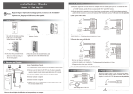
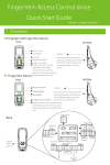
Download MA500 Access Control System User Manual
Transcript
Access Control Installation Guide & User Manual Important Note Document Privacy Note: Thank you for purchasing this product. Before using the unit, please read this manual carefully to avoid any unnecessary damage. The correct usage of this unit ensures fast and effect performance. No written consent will be given by our company, or individual representing our company to copy the content of this manual in part or in full, or distribute in any form what so ever. Except for the permission of the relevant holder, any person who copy’s, distributes, revises, modifies, extracts, decompiles, disassembles, decrypts, reverse engineers, leasing, transfers or sub-licenses the software, other acts of copyright infringement. All limitations applied to by law are excluded. Document use statement: Due to the constant renewal of products, the company can not undertake the actual product in consistence with the information in the document, also any dispute caused by the difference between the actual technical parameters and the information in this document. Please forgive any change without notice. Reserve the final rights of modification and interpretation. Table of contents Installation Guide 1. 2. 3. 4. 5. 6. 7. Equipment Installation ……………………………………………………………………………………………………………………………….......…i Structure and Function …………………………………………………………………………………………………………………………….........…ii Lock Connection …………………………………………………………………………………………………………………………………….......…....ii Connected with Other Parts …………………………………………………………………………………………………………………...…......…iv Connected with Power …………………………………………………………………………………………………………………………………..... iv Wiegand Output……………………………………………………………………………………………………………………………………..…..….... iv Communication ……………………………………………………………………………………………………………………………………….…........v User Manual 1. User Management................................................................................................................................................. 1 1.1 Administrator Operations ........................................................................................................................... 1 Change Administrator Password.......................................................................................................... 2 Open the Door by Entering the Administrator Password ...................................................................... 2 Forgot the Password by Administrator................................................................................................. 2 1.2 Add Users ................................................................................................................................................... 3 Batch registration (add series cards) .................................................................................................... 3 Backup registered user ........................................................................................................................ 4 1.3 User Authentication ................................................................................................................................... 4 1.4 Delete Users ............................................................................................................................................... 5 Delete a User ...................................................................................................................................... 5 Delete All Users................................................................................................................................... 6 2. Access Control Management ................................................................................................................................. 6 2.1 Configure Unlocking Duration ..................................................................................................................... 6 2.2 Configure Authentication Mode ................................................................................................................. 7 2.3 Configure Stealth Mode.............................................................................................................................. 7 2.4 Configure Door Sensor Mode ..................................................................................................................... 8 2.5 Configure Alarm ......................................................................................................................................... 8 Configure Error Operation-Triggered Alarm ......................................................................................... 9 Configure Tamper Alarm ..................................................................................................................... 9 Configure Delay for the Door Status Sensor ........................................................................................ 10 FAQ .......................................................................................................................................................................... 11 MA500 Access Control System Installation Guide 1. Equipment Installation Wall mount installation (1)Paste the mounting template (2)Remove the screws on (3)Take away the back plate. (4)Fix the back plate on on the wall. Drill the holes the bottom of device. the solid wall according according to the marks on the to the mounting paper. template. (holes for screws and wiring). (5)Fix the device to the back plate. (6)Tighten the screws at the bottom of the device. i Note: If it is not possible to drill on the hollow wall, please select a plastic box instead of iron plate. MA500 Access Control System Installation Guide 2. Structure and Function Access Control System Function: (1) If a registered user is verified, the device will trigger the lock control relay to open the door. (2) The door sensor will detect the on-off state. If the door is unexpectedly opened or improperly closed, the alarm relay will be triggered. (3) If the device is illegally removed, the alarm relay will be triggered. (4) External reader is supported. (5) External exit button is supported. (6) RS485, TCP/IP communication are supported. One PC can manage multiple devices. 3. Lock Connection Warning: Do not operate with Power connected. (1) The system supports NO LOCK and NC LOCK. It is supposed to connect with different terminals. (2)When the Electrical Lock is connected to the Access Control System, to prevent the self-inductance EMF feedback to the system, please connect one FR107 diode (shipped in the package) in parallel with the connection. NB: Do not reverse the polarities! ii MA500 Access Control System Installation Guide (I) Share power with the lock: + - Red +12V Black GND - Red +12V Black GND DC 12V DC 12V White SEN Black GND Gray FR107 - + NO LOCK BUT FR107 White SEN Black GND Gray BUT Blue NO Red COM Blue NO Red COM Yellow NC Yellow NC Orange AL- Orange AL- Orange AL+ Orange AL+ + - NC LOCK + Device share power with the lock: ULOCK=12V, I-ILOCK>1A……; And the lock is near to the device. (II) Separate power for both device and lock: +12V GND + DC 12V DC 12V + DC power - + + - FR107 White SEN Black GND Gray BUT Blue NO Red COM Yellow NC Orange AL- Orange AL+ + FR107 NO LOCK + DC power + - Red Black Red +12V Black GND - + White SEN Black GND Gray NO Red COM Yellow NC Orange AL- Orange AL+ NC LOCK ①: ‘I’: device output current, ‘ULOCK’: lock voltage, ‘ILOCK’: lock current. iii BUT Blue Device separate power with the lock: A. ULOCK =12V I-ILOCK ≤1A; B. ULOCK ≠12V; C. The lock is far apart from the device. D. We suggest user select “separate power for both device and lock”. MA500 Access Control System Installation Guide 4. Connected with Other Parts 5. Connected with Power The device working voltage is DC 12V, electric current is 500mA (50mA for standby current). Positive is connected with ‘+12V’, negative is connect with ‘GND’. (Do not reverse the polarities). 6. Wiegand Output The device supports standard Wiegand output, it is able to connect with various third party access control panel, which has Wiegand input. (1)Do not exceed 90m (meters) distance between the Device and Access Control Lock OR Card reader. (In the case of long distance installation, use the Wiegand Signal Extender, to minimize interference.) (2)To keep a balanced and stable Wiegand signal, connect the device, access control lock or card reader on the same "GND"(ground) port. iv MA500 Access Control System Installation Guide 7. Communication There are two modes that the PC software communicate and exchange information with the device: RS485 and TCP/IP, and supports remote control. (1) RS485 Mode: Please use specified RS485 wire, RS232/485 active converter, which consists of bus-type wiring. If the communication wire is longer than 100 meters, you need to parallel a terminal resistance on the receiving end, and resistance value is about 120Ω(ohm). RS485 Reader Function: Equipment supports RS485 reader function, can be through the RS485 communication connected to FR1200 reader which is for slaver achieves RS485 Anti-passback function. If RS485 of device is used for connecting with RS485 slave reader, then RS485 communication to PC is disabled. Diagram of the device connect to reader as below (The device act master): v MA500 Access Control System Installation Guide Diagram of the device connect to controller as below: Set the 485 address (device number) by Access3.5 software. (2) TCP/IP Mode: (A)Cross-Over cable: the device connects to PC directly (B)Straight-through: The device and PC are connected to Switch. vi MA500 Access Control User Manual Instructions Recommended Procedure: Step 1: Install the device and power on. Step 2: The administrator password is authenticated and changed. Step 3: Register users' fingerprints, cards, or passwords. Step 4: Configure access control parameters, including configuring the unlocking duration, authentication mode, stealth mode, door status sensor mode, and alarm. Note: The function like multi-card opening, first-card normal opening, register users, delete users, anti-pass back and so on in the access control system, refers to setting of Access3.5 software. Operation Instructions To enter into the system setting mode, first press * #, then enter system password and press # subsequently to enter into system setting mode. When entered into system setting mode, the status light (green) will be on with a beep sound. Users should enter any functional selections within 20 seconds. The reader will automatically terminate the system setting mode function after 20 seconds. The function of * key and # key: While the device is in the state of awaiting verification, press * key to enter the system, then press # key to confirm; while operating, press * to exit. Note: 1. Four-digit passwords are automatically verified. For passwords with less than four digits, press # to enter the verification process. 2. The initial administrator password is 1234. You are advised to change the initial password at the beginning. 1. User Management 1.1 Administrator Operations To ensure the security of the data in device, you can operate the device only after the administrator password is authenticated. 1 MA500 Access Control User Manual Change Administrator Password 1. Enter “* #” System password “ #” 2. Press [8]. (The indicator turns green and makes a beep.) 3. Enter a new administrator password. Failed. (The indicator turns red and makes three beeps.) 6. Exit. (The device automatically exits the process when the operation is completed.) 5. Succeeded. (The indicator turns green and makes a long beep.) YES 4. Enter the new administrator password again for authentication. Open the Door by Entering the Administrator Password 1. Enter “* #” system password “#” 2. Press [0] or[#]. (The indicator turns green and makes a long beep.) 5. Exit. (The indicator turns red and device automatically exits the process when the operation is completed.) 3. Press [0] or [#]. (The indicator turns green and makes a long beep.) 4. The door is opened. (The indicator turns green and makes a long beep.) Note: This function can be used to open the door. “#” key: Confirmation key. Forgot the Administrator password If the administrator password is forgotten, you can swap the magnet tamper switch three times after the alarm being triggered 30 seconds but no more than 60 seconds to restore initial administrator password. Meanwhile, it can restore factory settings, such as device number, IP address etc. (There is a long beep after 30 seconds of the tamper state.) 2 MA500 Access Control User Manual 1.2 Add Users Register the fingerprint or card of a user or register cards in batches. Add Users 1. Enter “* #” system password “#” 2. Press [1]. (The indicator turns green and makes a long beep.) 3.Enter a user ID Failed. (The indicator turns red and makes three beeps.) 6. Exit. (Press * to exit.) 5. Adding Users is successful. (The indicator turns green and makes a long beep.) YES 4. Register fingerprints or cards. (Press a finger three times to get a fingerprint or swipe the card once.) Note: 1. In the process of entering the user ID, 9 digits are verified automatically. For numbers with less than 9 digits, press # to enter the verification process. 2. If the process of registering fingerprint or card is failed, you can register the user again after the device indicator turns green. Registered users must not be registered again. 3. Password registration: please refer to Backup registered user. Batch registration (add series cards) 1. Enter “* #” system password “#” 2. Press [6]. (The indicator turns green and makes a long beep.) 3.Enter a user ID 4. Swipe the first card once only. Failed. (The indicator turns red and makes three beeps.) 7. Exit. (The device automatically exits the process when the operation is completed.) YES 6. Cards are successfully registered in YES 5. Enter the total number of batches.(The indicator turns green cards. and makes a beep.) Note: 1. In the process of entering the user ID, 9 digits are verified automatically. For numbers with less than 9 digits, press # to enter the verification process. If the use ID exists, the indicator turns red 3 MA500 Access Control User Manual and makes three beeps. 2. In the process of entering the total number of cards (0~999), three-digit numbers are automatically verified. For numbers with less than three digits, press # to enter the verification process. Press * to re-enter the total number of cards. 3. You must clear all the registered users before registering cards in batches. IDs of to-be-registered cards must be consecutive numbers. Backup registered user 1. Enter “* #” system password “#” 2. Press [3]. (The indicator turns green and makes a long beep.) 3.Enter a user ID, press the fingerprint or swipe the card Failed. (The indicator turns red and makes three beeps.) 6. Exit (Press * to exit.) 4. Backup fingerprint, password or card. YES 5. Succeeded (The indicator turns green and makes a long beep.) Note: 1. You can enter a user ID, press the fingerprint or swipe the card to backup registered user. The user ID, fingerprint or card must be registered, if it is not, the indicator turns red and makes three beeps. 2. Backup fingerprint and password, it will backup fingerprint when you press the fingerprint, and if you input numbers, it will backup the password. The indicator turns green and makes a long beep means it is successful. If it is failed, it will turn red and makes three beeps. 3. One time only backup one user. Press * to exit. 4. You can register password in step 4. 1.3 User Authentication Authenticate Users' Fingerprint/Card/Password After the device is powered on, it is in standby mode, for user authentication and unlocking the door. 4 MA500 Access Control User Manual 1. The device is in the authentication state. 2. Press fingerprint, swipe card, or YES enter password. Press # after entering a password. 3. The authentication is successful (The indicator turns green.) Failed. (The indicator turns red and makes two beeps.) Note: 1. Press # after entering a user ID for authentication, then entering a password, after that press #. 2. Duress password and Emergency password: First press #, enter a password, after that press # (You can configure the duress password and the emergency password by Access3.5 software). 3. You can open the door with the duress password when verification is password allowed only. 1.4 Delete Users Delete a user whose fingerprint or card is registered, or delete all users. Delete a User 1. Enter “* #” system password “#” 2. Press[2]. (The indicator turns green and makes a long beep.) 3. Enter a user ID, press the fingerprint, or swipe the card. Failed. (The indicator turns red and makes three beeps.) 6. Exit. (Press * or do not operate the device within 20 seconds.) 5. The user is deleted.(The indicator turns green and makes a long beep.) YES 4. Determine whether the user is authentic. Note: 1. You can enter a user ID, press the fingerprint or swipe the card to delete the user. The user ID, fingerprint or card must be registered, if it is not, the indicator turns red and makes three beeps. In the process of entering user IDs, 9 digit IDs are automatically verified. For IDs with less than 9 digits, press # to enter the verification process. 2. The device automatically enters the process of deleting the next user when a user is deleted, and the indicator turns green and makes a long beep. 3. Press* to exit. 5 MA500 Access Control User Manual Delete All Users 1. Enter “* #” system password “#” 2. Press[9]. (The indicator turns green and makes a long beep.) 5. Exit. (The device automatically exits the process when the operation is completed.) 3.Press[9] (The indicator turns green and makes a long beep.) 4. Deleting All Users is successful. (The indicator turns green and makes a long beep.) Note: 1. When it passes, the indicator turns green and buzzer rings. Then the indicator turns red and the buzzer rings again, that means the device is out of setting mode. 2. If you do not press 9 for the second time, the indicator turns red and makes three beeps, after that, the indicator turns red and makes a long beep, and the device exits the process. 2. Access Control Management 2.1 Configure Unlocking Duration 1. Enter “* #” system password “#” 2. Press [4]. (The indicator turns green and makes a long beep.) 5.Exit. (The device automatically exits the process when the operation is completed.) 3. Enter the unlocking duration.(Range: 1 to 10) 4. The unlocking duration is modified. (The indicator turns green and makes a long beep.) Note: Two-digit values are automatically verified. For values with less than two digits, press # to enter the verification process. Values greater than 10 are considered invalid. 6 MA500 Access Control User Manual 2.2 Configure Authentication Mode 1. Enter “* #” 2. Press [5]. system password (The indicator turns green “#” and makes a long beep.) 5.Exit. (The device automatically exits the process when the operation is completed.) 3. Enter the authentication mode. 4.The configuration is successful. (The indicator turns green and makes a long beep.) Note: 1. Input digitals 1~6, the system confirm automatically. Input digitals beside 1~6, the indicator turns red and makes three beeps, the setting is failing. When the indicator turns red and makes a beep, the device is exit. 2. Details about the authentication mode are as follows: Authentication Mode type Description Mode 1 (number1) PW Only password verification Mode 2 (number2) RF Only RF Card verification Mode 3 (number3) FP Only fingerprint verification Mode 4 (number4) FP/PW/RF fingerprint or password or RF verification Mode 5 (number5) RF&PW RF plus password verification Mode 6 (number6) FP&PW fingerprint plus password verification 2.3 Configure Stealth Mode If the Stealth mode is opened, the indicator light is off when device is in standby mode. 1. Enter “* #” system password “#” 6. Exit. (The indicator turns red and device automatically exits the process when the operation is completed.) 2. Press [0]. (The indicator turns green and makes a long beep.) 3. Press [3]. (The indicator turns green and makes a long beep.) 5. The configuration is successful. (The indicator turns green and makes a long beep.) 4. Configure stealth mode (0: enable; 1: disable). 7 MA500 Access Control User Manual Note: 1. If the stealth mode is enable, the indicator light prompts the status of this function when users authenticating or administrator operation. 2. In the process of configure stealth mode setting, press 0 or 1 which is verified automatically, the indicator turns green and makes a long beep when the authentication is successful, the device automatically exits the process when the operation is completed, and the indicator turns red and makes a long beep. 2.4 Configure Door Sensor Mode The door sensor switch includes three modes: NONE: The door sensor switch is not used. NO: The lock is open as long as the door is open. NC: The lock is closed after the door is closed. 1. Enter “* #” system password “#” 6.Exit. (The device automatically exits the process when the operation is completed.) 2. Press [0]. (The indicator turns green and makes a long beep.) 5. The configuration is successful. (The indicator turns green and makes a long beep.) 3. Press [5]. (The indicator turns green and makes a long beep.) 4. Configure the door sensor mode . (0: NONE; 1: NO; 2: NC) Note: 1. The door sensor mode configured here is used as the basis for the door sensor alarm. 2. In the process of configure door sensor mode setting, press 0 or 1 or 2 which is verified automatically, the indicator turns green and makes a long beep when the authentication is successful, the device automatically exits the process when the operation is completed, and the indicator turns red and makes a long beep. 2.5 Configure Alarm Configure Alarm setting The switch should be on, when it is set to be close, Error Operation-Triggered Alarm, Tamper Alarm, the Alarm Delay for the Door Status Sensor will be disabled. 8 MA500 Access Control User Manual 1. Enter “* #” system password “#” 6.Exit. (The red light flashing and device automatically exits the process when the operation is completed.) 2. Press [0]. (The indicator turns green and makes a long beep.) 5. The configuration is successful. (The indicator turns green and makes a long beep.) 3. Press [1]. (The indicator turns green and makes a long beep.) 4. Configure the alarm setting. (0: enable; 1: disable). Note: In the process of configure alarm setting, press 0 or 1 which is verified automatically, the indicator turns green and makes a long beep when the authentication is successful, the device automatically exits the process when the operation is completed, and the indicator turns red and makes a long beep. Configure Error Operation-Triggered Alarm If this function is enabled, alarms are generated if administrator fails the authentication upon three attempts. The administrator authentication is not allowed within 20 seconds after an alarm is generated. 1. Enter “* #” system password “#” 6. Exit. (The red light flashing and device automatically exits the process when the operation is completed.) 2. Press[0]. (The indicator turns green and makes a long beep.) 5. The configuration is successful. (The indicator turns green and makes a long beep.) 3. Press [2]. (The indicator turns green and makes a long beep.) 4. Configure the error operation-triggered alarm switch. (0: enable; 1: disable). Note: In the process of configure the error operation-triggered alarm switch, press 0 or 1 which is verified automatically, the indicator turns green and makes a long beep when the authentication is successful, the device automatically exits the process when the operation is completed, and the indicator turns red and makes a long beep. Configure Tamper Alarm If this function is enabled, alarms are generated upon device disassembly. Configure whether to enable the disassembly alarm. 9 MA500 Access Control User Manual 1. Enter “* #” system password “#” 2. Press[7]. (The indicator turns green and makes a long beep.) 5. Exit. (The red light flashing and device automatically exits the process when the operation is completed.) 3. Configure whether to enable the tamper alarm (0: enable; 1: disable) 4. The configuration is successful. (The indicator turns green and makes a long beep.) Note: In the process of configure whether to enable the tamper alarm, press 0 or 1 is automatically verified, the indicator turns green and makes a long beep when the authentication is successful, the device automatically exits the process when the operation is completed, and the indicator turns red and makes a long beep. Configure Delay for the Door Status Sensor DSen. Delay (Door Sensor Delay): indicates the delay in checking the door sensor after the door is open. If door sensor state is inconsistent with the normal state set by the door sensor switch, an alarm will be generated, and this period of time is regarded as the “door sensor delay”. 1. Enter “* #” system password “#” 6. Exit. (The indicator turns red and device automatically exits the process when the operation is completed.) 2. Press[0]. (The indicator turns green and makes a long beep.) 5. The configuration is successful. (The indicator turns green and makes a long beep.) 3. Press[4]. (The indicator turns green and makes a long beep.) 4. Configure the delay. (Range:1 to 254) Note: 1. In the process of configure the alarm delay, three-digit values are automatically verified. For values with less than three digits, press # to enter the verification process. The indicator turns green and makes a long beep when the authentication is successful, the device automatically exits the process when the operation is completed, and the indicator turns red and makes a long beep. Values greater than 254 are considered as invalid. 2. When alarm is triggered, the alarm process as follow: 1) Firstly, the buzzer inside the device beeps. 2) Secondly, after about 30 seconds, buzzer beep stop, and external alarm set off. 10 MA500 Access Control User Manual 3) On one hand, any valid user does the verification to stop alarm. On the other hand, if the current door sensor is coordinated with the set one, the terminal stops to alarm. FAQ Q: Does the device support connect with external fingerprint reader? How to set the RS485 address of the external fingerprint reader? A: Yes, the device support connect with one external fingerprint reader via RS485 communication way. For the setting of its RS485 address, please refer to corresponding document of reader. Normally, the address set via decimal code switches, and the RS485 address of reader only can be 0 or 1. Q: Which Wiegand-out format does device support? A: The device is preset with Wiegand 26-bit Output format, it also support Wiegand 34-bit Output format and other 9 format. (Please using Acccess3.5.2.1449 or above version to edit Wiegand out format) Q: What's the users and fingerprint capacity of device? A: 30,000 users and 3,000 fingerprint templates. 11


