1
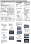
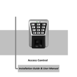
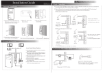
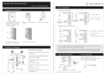
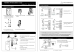
Installation Guide & User Manual Standalone Metal RFID Series Version: 2.1 Date: January, 2015 Important Note Document Privacy Note: Firstly thank you for purchasing the product. Before use, please read this manual carefully to avoid the unnecessary damage! The company reminds you that the proper user will improve the use affect and authentication speed. No written consent by company, any unit or individual isn’t allowed to excerpt, copy the content of this manual in part or in full, also spread in any form. Document use statement: Due to the constant renewal of products, the company can not undertake the actual product in consistence with the information in the document, also any dispute caused by the difference between the actual technical parameters and the information in this document. Please forgive any change without notice. Reserve the final rights of modification and interpretation. Contents Installation Guide 1. Equipment Installation 2. Structure and Function 3. Lock Connection 4. Connected with Other Parts ………………………………………………………………IV 5. Connect with Power…………………………………………………………..……………IV User Manual 1. User Management..................................................................................................... 1 1.1 Administrator Operations .................................................................................. 1 1.2 Add Users ........................................................................................................ 2 1.3 Register Eight Passwords for Opening the Door .............................................. 3 1.4 Authenticate User ............................................................................................. 3 1.5 Delete Users .................................................................................................... 4 2. Access Control Management .................................................................................... 5 2.1 Configure Unlocking Duration .......................................................................... 5 2.2 Configure Authentication Mode ........................................................................ 5 2.3 Configure Concealed Mode .............................................................................. 6 2.4 Configure Door Sensor Mode ........................................................................... 6 2.5 Configure Alarm ............................................................................................... 7 2.6 SRB ................................................................................................................. 8 2.7 Factory Reset................................................................................................... 9 3. Switch Working Mode................................................................................................ 9 3.1 Controller Mode Switch to Reader Mode .......................................................... 9 3.2 Reader Mode Switch to Controller Mode ........................................................ 10 Appendix ..................................................................................................................... 11 Packing List ................................................................................................................ 11 1. Equipment Installation 1 Optical Tamper Switch 2 Remove the screw on the bottom of device. 4 3 Fix the back cover on the wall. 6 5 Fix the device to the back cover. Fix the screw. Please pick off the plastic 6 Exposed wire Take away the back cover. when exposed wire Buried wire I 2. Structure and Function Access Control System Function (1) If a registered user is verified, the device will send a signal to unlock the door. (2) Door Sensor will detect the door is open or not. If the door is unexpectedly opened or improperly closed, the alarm will be triggered. (3) It supports Exit Button; it is convenient to open the door inside. (4) It supports Smoke Detector etc., it will alarm and open the door when receives the signal of detector. (5) It supports Door Bell; visitors could call by the door bell. (6) If the device is dismantled, it will send an alarm signal. Linkage Function This device has an Auxiliary Input interface (AUX+) which allows it to be connected with an external source, for instance a smoke detector, gas detector, infrared sensor or emergency switch. Trigger Linkage Once detectors or sensors are connected to AUX+ and are triggered, the II system receives the linkage signal and would generate an alarm and open the door, the door keeps open and alarm keeps on until the linkage is canceled. Cancel Linkage The linkage can be canceled when a user is verified, or the Administrator opens the door with password. 3. Lock Connection Warning: No operation when power on! (1) The system supports NO LOCK and NC LOCK. For example the NO LOCK (normally open by power on) is connected with NO terminal, and the NC LOCK is connected with NC terminal. (2) When the Electrical Lock is connected to the Access Control System, you need to parallel one FR107 diode (equipped in the package) to prevent the self-inductance EMF affecting the system, do not reverse the polarities. (I) Share power with the lock ULOCK=12V, I ≥ IDevice + ILock (The maximum operating current of device is 100mA, and the rated current is 60mA); And the lock is near to the device. III (II) Does not share power with the lock Device does not share power with the lock: ULOCK=12V, I < IDevice + ILock (The maximum operating current of device is 100mA, and the rated current is 60mA); ULOCK≠12V; The lock is far from the device. I: device output current; ULOCK: lock voltage; ILOCK: lock current. 5. Connect with Power 4. Connect with Other Parts Voltage output ≤ DC 12V for Alarm IV Input DC12V, ≤110mA (≤80mA standby) Positive is connected with +12V, negative is connected with GND (do not reverse the polarities). Recommended procedure Step 1: Power on after the device is completely installed on the wall. Step 2: Change the administrator password, and configure access control parameters, including unlocking duration, authentication mode, concealed mode, door sensor mode, and alarm etc. Step 3: Register users' cards, or eight passwords. 1. User Management 1.1 Administrator Operations To ensure data security of the device, you can operate the device only after the administrator password is authenticated. Authenticate the Administrator Password 1. Press [*] (The indicator is off and makes a long beep.) 2. Press [#] . (You can authenticate the password.) 3. Enter the administrator password. (The initial password is 1234.) 5. Exit. (Press [*] or do not operate the device within 20 seconds ,The indicator turns red and makes a long beep, then automatically exit.) 4. The authentication is successful. (The indicator turns blue.) Yes Note: The initial administrator password is 1234. Change Administrator Password 1. The administrator password is authenticated. 2. Press [8]. (You can change the password.) 3. Enter a new administrator password. Failed. (The indicator turns red and makes three beeps.) 6. Exit. (The indicator turns red and makes a long beep, then automatically exit.) 5. Succeed. (The indicator turns blue and the makes a long beep.) Yes 4. Enter the new administrator password again for authentication. Note: Four-digit passwords are automatically verified. For passwords with less than four digits, press [#] to enter the verification process. 1 Open the Door by Entering the Administrator Password 1. The administrator password is authenticated. 2. Press [0]. (The indicator turns blue and makes a long beep.) 3. Press [0]. (The indicator turns blue and makes a long beep.) 5. Exit. (The indicator turns red and makes a long beep, then automatically exit.) 4. The door is opened (The indicator turns blue and makes a long beep.) Note: This function can be used to open the door. Administrator Password is Forgotten? If the administrator password is forgotten, please dismantle the device and wait 30 seconds when there is a long beep, then press the Optical Tamper Switch three times to reset to the initial administrator password, each press shall take 2~5 seconds and it comes a beep each time, note this operation must be done within 30 seconds. It is successfully reset when it has a long beep after the third press; the Red LED blinks and quits the operation by itself. Note: The initial administrator password is 1234. 1.2 Add Users Register the card of a user or register cards in batches. Add Users 1. The administrator password is authenticated. 2. Press [1]. (The indicator turns blue and makes a long beep.) 4. Register cards. ( Swipe the card once.) 3. Input user ID twice (The indicator turns blue and makes a long beep.) 6. Exit. (Press [*], the indicator turns red and makes a long beep, then automatically exit. ) 4. Register cards. ( Swipe the card once.) 5. Adding users successfully. (The indicator turns blue and makes a long beep.) Note: 1. Nine-digit user ID is automatically verified. For user ID with less than nine-digit, press [#] to confirm. 2. If the user ID is not available, the ID number increases automatically. It continues to register new one once a user is successfully registered. 3. The registration fails if the user ID or the card has been registered (the indicator turns 2 red and makes three short beeps). When the indicator turns blue, you can register the user again. If you fail in swiping card or entering user ID three times, the device will enter the standby state. Register Cards in Batches 1. The administrator password is authenticated. 2. Press [6]. (Registering Cards in Batches.) 3. Swipe the first card once. (Swipe the card once.) Failed. (The indicator turns red and makes three beeps.) 6. Exit. (The indicator turns red and makes a long beep, then automatically exit.) 5. Cards are registered in batches successfully. Yes 4. Enter the total number of cards. Note: 1. In the process of entering the total number of cards, three-digit numbers are automatically verified. For numbers with less than three digits, press [#] to enter the verification process. Press [*] to reenter the total number of cards. 2. IDs of to-be-registered cards must be consecutive numbers. 1.3 Register Eight Passwords for Opening the Door This device supports 8 passwords, each password has a Group ID ranges from 1~8. The default password value is 0 for all groups, which means passwords are disabled. You can modify the passwords under 8 groups to open the door. 1. The administrator password is authenticated. 2. Press [3]. (The indicator turns blue and makes a long beep.) 3. Enter the group ID of password.(Group ID: 1 ~ 8.) 7. Exit. (Press [*], the indicator turns red and makes a long beep, then automatically exit) 6. Register successfully. (The indicator turns blue and makes a long beep.) 4. Enter the password twice. (The password consists of four digits.) Note: If a password is successfully changed, enter the Group ID to change next one. 1.4 Authenticate User Card / Password Authentication 3 After the device is powered on, it enters the authentication state for unlocking the door. 1. The device is in the authentication state. 2. Swipe the card, or enter Yes 3. The authentication is the password. Press [#] successful. (The indicator after entering the turns blue and makes a password. long beep.) Failed. (The indicator turns red and makes two short beeps.) Note: Press [#] after entering a password for authentication. The door opens if the entered password is identical with one of the eight passwords for opening the door. 1.5 Delete Users Delete a user whose card is registered, or delete all users. Delete a User 1. The administrator password is authenticated. 2. Press [2]. (The indicator turns blue and makes a long beep.) 3. Swipe the user card or input user ID once which to be deleted. Failed. (The indicator turns red and makes three beeps.) 6. Exit. (Press [*] or do not operate the device within 20 seconds, the indicator turns red and makes a long beep, then automatically exit.) 5. The user is deleted. (The indicator turns blue and makes a long beep.) Yes 4. Determine whether the user is authentic. (The indicator turns blue and makes a long beep.) Note: 1. You can swipe the card or input user ID to delete a user. Nine-digit user ID is automatically verified. For user ID with less than nine-digit, press [#] to confirm. 2. The device automatically enters the process of deleting the next user when a user is deleted, or press [*] to exit. 4 Delete All Users 1. The administrator password is authenticated. 2. Press [9]. (The indicator turns blue and makes a long beep.) 3. Press [9]. (The indicator turns blue and makes a long beep.) 5. Exit. (The indicator turns red and makes a long beep, then automatically exit.) 4. Deleting All Users is successful. (The indicator turns blue and makes a long beep.) Note: Press [9] for automatic confirmation. Other values are considered invalid. If an invalid value is entered, the device indicator turns red, and the device makes a long beep and exits the process. 2. Access Control Management 2.1 Configure Unlocking Duration 1. The administrator password is authenticated. 2. Press [4]. (The indicator turns blue and makes a long beep.) 3. Enter the unlocking duration. (range: 1s to 254s) 5. Exit. (The indicator turns red and makes a long beep, then automatically exit.) 4. The unlocking duration is modified. (The indicator turns blue and makes a long beep.) Note: The unit of Unlocking Duration is second. Three-digit values are automatically verified. For values with less than three digits, press [#] to enter the verification process. 2.2 Configure Authentication Mode 1. The administrator password is authenticated. 2. Press [5]. (The indicator turns blue and makes a long beep.) 3. Enter the authentication mode. 5. Exit. (The indicator turns red and makes a long beep, then automatically exit.) 4. The configuration is successful. (The indicator turns blue and makes a long beep.) 5 Note: 1. When the authentication mode is RF & password, swipe card and then enter the passwords please. 2. Details about the authentication modes are as follows: Authentication Mode Value Description PW 1 Only password verification RF 2 Only RF Card verification RF/PW (default) 3 RF or password verification RF&PW 4 RF and password verification 2.3 Configure Concealed Mode If the Concealed Mode is enabled, the indicator is off. 1. The administrator password is authenticated. 2. Press [0]. (The indicator turns blue and makes a long beep.) 3. Press [3]. (The indicator turns blue and makes a long beep.) 6. Exit. (The indicator turns red and makes a long beep, then automatically exit.) 5. The configuration is successful. (The indicator turns blue and makes a long beep.) 4. Configure the concealed mode. (0: enable; 1: disable). Note: An indicator blinks to indicate the status of this function when users are authenticating their cards or passwords. 2.4 Configure Door Sensor Mode The door sensor has three modes: ● NONE: The door sensor is disabled. ● NO: The door sensor will send an alarm signal if it detects the door is closed. ● NC: The door sensor will send an alarm signal if it detects the door is open. 6 1. The administrator password is authenticated. 2. Press [0]. (The indicator turns blue and makes a long beep.) 3. Press [5]. (The indicator turns blue and makes a long beep.) 6. Exit. (The indicator turns red and makes a long beep, then automatically exit.) 5. The configuration is successful. (The indicator turns blue and makes a long beep.) 4. Configure the door sensor mode. (0: Normally Open; 1: Normally Closed; 2: Disabled). Note: The door sensor mode configured here is used as the basis for the door sensor alarm. 2.5 Configure Alarm Configure Alarm Switch The alarm switch is turned on by default. When it’s disabled, then Error Operation-Triggered Alarm and the Alarm Delay for the Door Status Sensor will be disabled, but Tamper Alarm still works. 1. The administrator password is authenticated. 2. Press [0]. (The indicator turns blue and makes a long beep.) 3. Press [1]. (The indicator turns blue and makes a long beep.) 6. Exit. (The indicator turns red and makes a long beep, then automatically exit.) 5. The configuration is successful. (The indicator turns blue and makes a long beep.) 4. Configure the alarm setting. (0: enable; 1: disable). Configure Error Operation-Triggered Alarm Alarms will be generated if the administrator fails the authentication upon three attempts under this function enabled, and it is not allowed to continue within 20 seconds. 1. The administrator password is authenticated. 2. Press [0]. (The indicator turns blue and makes a long beep.) 3. Press [2]. (The indicator turns blue and makes a long beep.) 6. Exit. (The indicator turns red and makes a long beep, then automatically exit.) 5. The configuration is successful. (The indicator turns blue and makes a long beep.) 4. Configure the error operation-triggered alarm switch. (0: enable; 1: disable) 7 Configure Tamper Alarm If this function is enabled, alarms will be generated when device is dismantled from the wall. 1. The administrator password is authenticated. 2. Press [7]. (The indicator turns blue and makes a long beep.) 3. Configure whether to enable the tamper alarm. (0: enable; 1: disable) 5. Exit. The indicator turns red and makes a long beep, then automatically exit.) 4. The configuration is successful. (The indicator turns blue and makes a long beep.) Configure Alarm Delay for the Door Status Sensor DSen. Delay (Door Sensor Delay): It is to configure the time how long would the door sensor would do check the door status. 1. The administrator password is authenticated. 2. Press [0]. (The indicator turns blue and makes a long beep.) 3. Press [4]. (The indicator turns blue and makes a long beep.) 6.Exit. (The indicator turns red and makes a long beep, then automatically exit.) 5. The configuration is successful. (The indicator turns blue and makes a long beep.) 4.Configure the alarm delay. (range: 1s to 254s) Note: Three-digit values are automatically verified. For values with less than three digits, press [#] to confirm. Values greater than 254 are considered invalid. 2.6 SRB Security Relay Box (SRB) is a relay switch to control electric lock, exit button to provide higher security level for access control. It is installed on a secured place and connected with standalone access control devices by Wiegand out. Note: For electrical parameters and connection guide, please consult SRB Simple Access Controller Connection Guide. 8 2.7 Factory Reset 1. The administrator password is authenticated. 2. Press [0]. (The indicator turns blue and makes a long beep.) 3. Press [9]. (The indicator turns blue and makes a long beep.) 6.Exit. (The indicator turns red and makes a long beep, then automatically exit.) 5. The configuration is successful. (The indicator turns blue and makes a long beep.) 4. Press [9]. (a short beep) The Factory Default Settings Unlock Authentication Mode Door Sensor Mode Alarm Switch Error Operation-Triggered Alarm Switch Tamper Alarm Switch Concealed Mode Unlocking Duration Door Sensor Delay RF/PW None Enabled Enabled Enabled Disabled 5 seconds 15 seconds 3. Switch Working Mode This device could work as a standalone controller or as a wiegand reader, which offers flexibility to use depending on actual needs. It is a standalone controller by default setting but you could switch the working mode by the following instruction. If the indicator blinks blue, indicates that the device is set to Controller Mode. If the indicator stays in red, indicates that the device is set to Reader Mode. Note: For wiring diagram of reader mode, please consult Appendix. 3.1 Controller Mode Switch to Reader Mode 1. The administrator password is authenticated. 2. Press [0]. (The indicator turns blue and makes a long beep.) 6. Exit. (The indicator turns red and makes a long beep, then automatically exit.) 5. Set mode successfully. (The indicator turns blue and makes a long beep.) 3. Press [6]. (The indicator turns blue and makes a long beep.) 4. Press [1]. (The indicator turns blue and makes a long beep.) Note: The device makes three short beeps when fails in setting, then the indicator turns red and makes a long beep, then automatically exit. 9 Set Weigand Format When the device is in Reader Mode, hold and press [*] five seconds, press [#] when the red indicator turns off, then input administrator password to enter the device. It can be set to Weigand 26 or Weigand 34. 1. The administrator password is authenticated. 2. Press [0]. (The indicator turns blue and makes a long beep.) 6. Exit. (The indicator turns red and makes a long beep, then automatically exit.) 5. Set format successfully. (The indicator turns blue and makes a long beep.) 3. Press [7]. (The indicator turns blue and makes a long beep.) 4. Set Weigand format (0:WG26, 1:WG34.) Note: The device makes three short beeps when fails in setting, then the indicator turns red and makes a long beep, then automatically exit. 3.2 Reader Mode Switch to Controller Mode When the device is in Reader Mode, hold and press [*] five seconds, press [#] when the red indicator turns off, then input administrator password to enter the device. 1. The administrator password is authenticated. 2. Press [0]. (The indicator turns blue and makes a long beep.) 3. Press [6]. (The indicator turns blue and makes a long beep.) 6. Exit. (The indicator turns red and makes a long beep, then automatically exit.) 5. Set mode successfully. (The indicator turns blue and makes a long beep.) 4. Press [0]. (The indicator turns blue and makes a long beep.) Note: The device makes three short beeps when fails in setting, then the indicator turns red and makes a long beep, then automatically exit. 10 Appendix Wiring Diagram of Controller Mode Wiring Diagram of Reader Mode Red: DC 12V Light Blue: SEN Red: DC 12V Black: GND Black: GND Gray: BUT Green: WD0 White: WD1 Light Blue: LED Yellow: NC Purple: BELL+ (Bell) Gray: BEEP Pink: COM Brown: BELL- (Bell) Purple: BELL+ (Bell) Blue: NO Brown: BELL- (Bell) Weigand Output Linkage Function Green: WD0 Orange: AL (Alarm) White: WD1 Light Green: AUX+ Packing List Access Device & Mounting Plate 4 Screws 1 Card 4 Diodes (FR107) 4 Wall Plugs 1 Star-shaped Screw 11 Screwdriver 1 Installation Guide