1
1
Introduction
1.1
Project Sponsor
The Vanderbilt University School of Engineering (VUSE) is sponsoring this project.
Lewis Saettel, a manager of VUSE, is in charge of programming the locks so that
appropriate faculty, staff and students can access rooms within Featheringhill and
Jacobs Hall.
1.2
Executive Summary
Locknetics (Ingersoll Rand/Schlage) locks secure most areas of Featheringhill and
Jacobs Hall. The Computer Interface Programming (CIP) module is the device that is
used to program the door. Lewis Saettel, our project sponsor, and manager of facilities
at Vanderbilt University School of Engineering uses this module daily to grant (or
remove) students and faculty access to the doors in the engineering building. Because
the locks are reprogrammed on a frequent basis, the programming hardware
subsequently suffers damage over time. After multiple uses, the pins of the CIP module
break, or begin to break in such a way that they are no longer useable. About four new
modules are purchased yearly, totaling over $1000 of programming equipment
purchases.
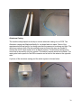
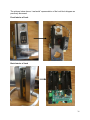
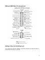
Various issues were encountered as problems with the existing system. The banana
pins of the CIP module are unable to withstand stress of the CIP module and bulky
cable hanging from the module. An additional source of stress arises from the banana
pins being the same length, but the banana pin slots being inconsistent in depths. This
requires the user programming the locks to have to maneuver the module in a manner
that adds stress to the pins. In addition to the stress issues, common occurrences are
electrical connection problems between the CIP module and the lock due to the poor fit
of the pins. In many cases, this requires multiple attempts to program the locks.
These problems have made it necessary to produce a method for programming the
locks that will alleviate the hassle of frequently reordering CIP modules due to broken
pins and save money. The final solution that was implemented an entirely new design
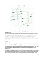
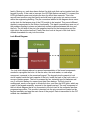
for the CIP module. Circuit analysis was performed which consisted of tracing the
original circuit inside the CIP module using a high magnification microscope and lamp.
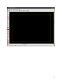
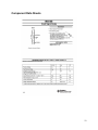
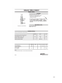
The components and their values were identified and ordered. Next, a PSpice
schematic of the existing circuit was formulated and the design was tested for its
functionality on an electric breadboard. Finally, a printed circuit board was ordered and
soldered. New casing, wiring, and pin handles were also created with the assistance of
a machine shop. The new model allowed for the depth of the banana pins to be
3