1
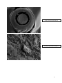
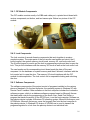
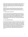
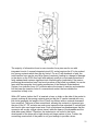
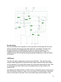
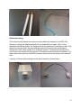
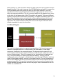
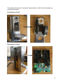
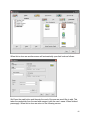
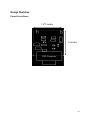
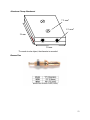
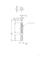
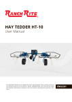
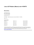
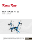
A picture of the constructed PCB is shown below.
Pin Handles and Wiring
We enlisted the machine shop associated with the Vanderbilt Physics Department to
help us with several parts of our final hardware design. The first of these parts was the
custom handles that we now have. One problem that the design of the original is that
pins were fixed in relation to one another. This coupled with the fact that the holes with
which the pins interface were not leveled but the pins were led to extra stress being
placed on the pins when trying to make a good electrical contact.
In order to combat this problem we wanted to make the interface with the lock as free as
possible. To accomplish this we made the pins connected to handles which were in
turn connected to two separate wires. This allowed for a great deal of freedom.
The pin handles themselves were custom made at the machine shop. They were
molded from plastic and made to fit our banana pins in terms of threading and pin
diameter. The pins are simply screwed into the handles due to the custom threading
inside of the handles.
The pins had holes drilled into them bottom of them. The 18 gauge wire was placed in
these holes. The pins were heated up with a high power soldering iron and rosin core
solder was placed in the pin hole with the wire and melted to the exposed copper wire
that composed the wire. This wire was then run through the pin handle and the pin was
screwed into the handle. This made electrical connection with the pin/pin handle and the
wire.
The wires that extended from the pins were connected on the other end to the PCB. To
make a cleaner design we put the two individual wires inside a heat shrink tubing. The
heat shrink tubing was made to shrink using a novel idea of a paint stripping tool.
Pictures of the pin handles and wiring are shown below.
29