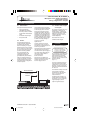
1
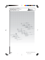
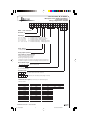
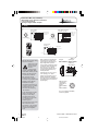
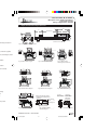
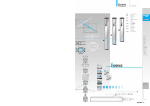
www.balluff.com
Sensors Worldwide
Technical Description / User’s Guide
BTL5-I/K/L/M/P_-M_-R-S32/KA_
Micropulse Linear Transducer
Analog & Digital-Pulse Outputs
Low-Profile Housing
™
R_102003.pmd
1
12/11/2003, 4:06 PM
BTL5-I/K/L/M/P_-M_-R-S32/KA_
Micropulse Linear Position Transducer
Low-Profile Housing
Analog & Digital-Pulse Outputs
1-800-543-8390 • WWW.BALLUFF.COM
2
R_102003.pmd
™
2
12/11/2003, 4:06 PM
BTL5-I/K/L/M/P_-M_-R-S32/KA_
Micropulse Linear Position Transducer
Low-Profile Housing
Analog & Digital-Pulse Outputs
™
1 2 3
Rod Style
4 5 Rugged,
6 7 8
B T L -
5
9 10 11 12 13 14 15 16 17 18 19 20 21 22
Compact
- A 1 1
Rod Style
- M 0 3
0 5 -
R - S 3 2
K A 0
5
Balluff - Linear Transducer
Generation 5
Output Type
A
B
C
E
G
=
=
=
=
=
I =
K =
L =
M=
P =
0 to 10Vdc
-5 to +5Vdc
0 to 20 mA
4 to 20 mA
-10 to +10 Vdc
Differential
Differential
Differential
Differential
Differential
start/stop with tri-state
stop - leading edge active
pulse-width modulated
start/stop - leading edge active
start/stop - trailing edge active
Compact,
bolt-in
Rod Style
Supply Voltage
1 = 24 Vdc ±20%
Analog Output Operation
(Leave Blank for Digital Versions)
Voltage type (Output type A, B & G)
1 = User selectable rising or falling
Current type (Output type C & E)
0 = Minimum output at connector end (rising towards opposite end)
7= Maximum output at connector end (falling towards opposite end)
Normal Stroke Length
0
3
0
5
= 305mm active stroke
Housing Type
R = Low Profile Housing
Connection Type
S
3
2
K
A
0
= 8-pin quick disconnect metal connector
5
= Cable out (5m standard; specify length in meters)
Standard Stroke Lengths (consult factory for additional lengths)
Electrical Stroke
inches
2
3
4
5
6
7
8
9
10
11
12
13
mm
0051
0077
0102
0127
0152
0178
0203
0230
0254
0280
0305
0330
inches
15
16
18
20
22
24
26
28
30
32
36
40
mm
0381
0407
0457
0508
0560
0610
0661
0711
0762
0813
0914
1016
inches
42
48
50
60
70
80
90
100
110
120
130
142
mm
1067
1220
1270
1524
1778
2032
2286
2540
2794
3048
3302
3606
inches
148
156
mm
3759
3962
WWW.BALLUFF.COM • 1-800-543-8390
R_102003.pmd
3
3
12/11/2003, 4:06 PM
BTL5-I/K/L/M/P_-M_-R-S32/KA_
Micropulse Linear Position Transducer
Low-Profile Housing
Analog & Digital-Pulse Outputs
1
Contents
1
1.1
1.2
1.3
1.4
Safety Advisory .............
Proper application ............
Qualified personnel ..........
Use and inspection ..........
Scope ..............................
2
Function and
Characteristics ..............
Characteristics ................
Function ...........................
Available stroke lengths
and magnets ...................
2.1
2.2
2.3
4
4
4
4
4
5
5
5
5
3
3.1
3.2
3.3
Installation ....................
Transducer installation ....
Floating magnets .............
Captive magnets .............
4
Wiring ............................. 8
5
5.1
5.2
5.3
5.4
5.5
5.6
Startup ...........................
Check connections .........
Turning on the system .....
Check output values .......
Check functionality ..........
Fault conditions ...............
Noise elimination .............
6
Versions (indicated
on part label) ................ 9
7
7.1
Technical Data ............. 10
Dimensions, weights,
ambient conditions ......... 10
Supply voltage (external) . 10
Outputs .......................... 10
Connection to processor..10
Included in shipment ...... 10
Magnets
(order separately) ........... 10
Accessories (optional) .... 10
7.2
7.3
7.4
7.5
7.6
7.7
5
5
6
7
9
9
9
9
9
9
9
Safety Advisory
Read this manual before installing and operating the Micropulse
Transducer.
1.1
Proper application
The BTL5 Micropulse transducer is intended to be installed in a
machine or system. Together with a controller (PLC) or a processor
(BTA) it comprises a position measuring system and may only be
used for this purpose.
Unauthorized modifications and non-permitted usage will result in the
loss of warranty and liability claims.
1.2
Qualified personnel
This guide is intended for specialized personnel who will perform the
installation and setup of the system.
1.3
Use and inspection
The relevant safety regulations must be followed when using the
transducer system. In particular, steps must be taken to ensure that
should the transducer system become defective, no hazards to
persons or property can result. This includes the installation of
additional safety limit switches, emergency shutoff switches and
maintaining the permissible ambient conditions.
1.4 Scope
This guide applies to the model BTL5-A/C/E/G...R... Micropulse
transducer with analog outputs
and to model BTL5-P/I/K/L/
M...R... Micropluse transducer
Note: For special versions,
with digital output.
which are indicated by an An overview of the various
models can be found in section
6 Versions (indicated on part
label) on page 9.
SU_ _ _ designation in the
part number, other technical
data may apply (affecting
calibration, wiring, dimensions etc.).
Emission tests:
RF Emission
EN 55011 Group 1, Class A
Noise immunity tests:
Static electricity (ESD)
Severity level 3
89/336/EEC (EMC Directive) EN 61000-4-2
Electromagnetic fields (RFI)
and the EMC Law. Testing in our EN 61000-4-3 Severity level 3
EMC Laboratory, which is
Fast transients (Burst)
accredited by DATech for Testing EN 61000-4-4 Severity level 3
Electromagnetic Compatibility,
Surge
has confirmed that Balluff
EN 61000-4-5 Severity level 2
products meet the EMC
Line-induced noise induced by
requirements of the following
high-frequency fields
Generic Standards:
EN 61000-4-6
Severity level 3
•EN 50081-2 (emission)
Magnetic fields
•EN 61000-6-2 (noise immunity) EN 61000-4-8 Severity level 4
The CE Mark verifies
that our products meet
the requirements of
EC Directive
The following patents
have been granted in
connection with this
product:
US Patent 5 923 164
Apparatus and Method
for Automatically Tuning
the Gain of an Amplifier
1-800-543-8390 • WWW.BALLUFF.COM
4
R_102003.pmd
™
4
12/11/2003, 4:06 PM
BTL5-I/K/L/M/P_-M_-R-S32/KA_
Micropulse Linear Position Transducer
Low-Profile Housing
Analog & Digital-Pulse Outputs
™
2
Function and Characteristics
2.1
Characteristics
Micropulse transducers feature:
— Very high resolution,
repeatability and linearity
— Immunity to shock, vibration,
contamination and electrical
noise
— An absolute output signal
— IP 67 per IEC 529
2.2
Function
The Micropulse transducer
contains a tubular waveguide
enclosed by an extruded
aluminum housing. A magnet
attached to the moving member
of the machine is moved across
the top of the housing and its
position constantly updated.
The magnet defines the
measured position on the
waveguide. An internally
generated INIT pulse interacts
with the magnetic field of the
magnet to generate a magnetostrictive torsional wave in the
waveguide which propagates at
ultrasonic speed.
2.3
The torsional wave arriving at the
end of the waveguide is absorbed
in the damping zone. The wave
arriving at the beginning of the
waveguide creates an electrical
signal in the coil surrounding the
waveguide. The propagation time
of the wave is used to derive the
position. Depending on the version
the corresponding value is output
as either an analog voltage or
current or as various
digital formats.
On both ends of the nominal
stroke length is an area which
provides an unreliable signal, but
which may be entered.
The electrical connection between
the transducer, the processor/
controller and the power supply is
via a cable, which depending on
the version is either fixed or
connected using a
female connector.
Dimensions for installing the
Micropulse transducer and for the
magnets and control arm are
found on pages 6 and 7.
Available stroke lengths
and magnets
To provide for optimum fit in any
application, a wide range of
stroke lengths, magnets and
mounting hardware is available.
Magnets, control arms and
mounting brackets must be
ordered separately.
See inside front cover for
available stroke lengths.
3
Installation
3.1
Transducer installation
Ensure that no strong
electrical or magnetic fields
are present in the immediate
vicinity of the transducer.
Any orientation is permitted. The
mounting brackets and cylinder
head screws allow the transducer to be mounted on a flat
machine surface. These should
be evenly spaced
(Fig. 3-1).
The recommended spacing for
long transducers and extreme
conditions (e.g. strong shock or
vibration): A = 80 mm; spacing
between the individual brackets
B = 250 mm.
The isolation bushings are used
to electrically insulate the
transducer from the machine
(Fig. 3-1 and chapter 5.6
noise elimination).
Electrical Stroke
Present position
of the magnet
element
The Micropulse transducer in
profile housing is suitable both
for floating, i.e. non-contacting
magnets (Page 6) and for
captive magnets (Page 7).
Fig. 2-1
WWW.BALLUFF.COM • 1-800-543-8390
R_102003.pmd
5
5
12/11/2003, 4:06 PM
BTL5-I/K/L/M/P_-M_-R-S32/KA_
Micropulse Linear Position Transducer
Low-Profile Housing
Analog & Digital-Pulse Outputs
3
™
Installation (cont.)
105
5
70
95
Nominal stroke
46
32
12
35
1
15
50
68
M5x22 ISO 4762
Fig 3-1: Transducer BTL5...R Dimensions
55
38
C
21
Ø4.2
28
28
25
C
Ø4.2
15
C
Ø8 x 3.2 deep c-bore
7.5
16.5
D
40 + 10
D
50
36 + 2
15
20
40
9
28 + 4
D
25
Ø4.2
14
20
45
45
28
M5 x 8
50
68
68
50
68
3.2 Floating magnets
The floating magnet (Figs. 3-2
to 3-4) is attached to the
moving member of the
machine using non-magnetizable screws (brass, aluminum). To ensure the accuracy
of the transducer system, the
moving member must carry
the magnet on a track parallel
to the transducer.
Magnet type
Distance
“D”
Offset
“C”
BTL5-P-3800-2
0.1 ... 4
±2
BTL5-P-5500-2
5 ... 15
± 15
BTL5-P-4500-1
0.1 ... 2
±2
BTL5-P-4500-1 magnet,
special features: Multiple
magnets on the same
transducer can be turned on
and off individually (PLC
control signal).
Ensure that the
distance E between
parts made of
magnetizable material
and the
BTL5-P-5500-2 magnet is at
least 12 mm (Fig. 3-3).
The following table provides
figures in [mm] for the spacing
which must be maintained
between magnet and
transducer and for the
permissible center offset:
The stroke range is offset
4 mm towards the BTL
connector/cable (Fig. 3-4).
1-800-543-8390 • WWW.BALLUFF.COM
6
R_102003.pmd
Fig. 3-4: BTL5-P-4500-1
electromagnet (24 V/100 mA)
Fig. 3-3: BTL5-P-5500-2 magnet
Fig. 3-2: BTL5-P-3800-2 magnet
6
12/11/2003, 4:06 PM
BTL5-I/K/L/M/P_-M_-R-S32/KA_
Micropulse Linear Position Transducer
Low-Profile Housing
Analog & Digital-Pulse Outputs
™
Installation (cont.)
40.5
21
M5
15.5
M5
23.5
23.5
40.5
21
15.5
3
28
18
28
37
29
35
27
18
50
50
68
68
Fig 3-6: BTL5-N-2814-15 Magnet
Fig 3-5: BTL5-M-2814-15
Magnet
70.5
40
23
18°
−
18°
14.5
14.5
±18°
40
28
31
24
41
24
M5 x 10
50
68
50
Fig 3-8:BTL-R-2814-15 Magnet
68
Fig 3-7: BTL-F-2814-15
Magnet
3 . 3 Captive magnets
stroke range. It is assumed
that the BTL5-F-2814-1S
magnet is connected to the
machine member using a
connecting rod. The
BTL2-GS08...A connecting rod
(Fig. 3-9) is available as an
accessory (please indicate
length LS when ordering).
Ball joint "B" DIN 71805,
rotates horizontally (part of
BTL5-F-2814-1S) magnet)
08
Lateral forces are to be
avoided when using captive
magnets (Figs. 3-6 thru 3-8).
Connections are required
here which permit the
corresponding degree of
freedom with respect to the
direction of movement of the
magnet along the
Jam nut DIN 934 M5
Swivel eye DIN 648
Fig. 3-9: BTL2-GS08-_ _ _ _-A
Connecting Rod
WWW.BALLUFF.COM • 1-800-543-8390
R_102003.pmd
7
7
12/11/2003, 4:06 PM
BTL5-I/K/L/M/P_-M_-R-S32/KA_
Micropulse Linear Position Transducer
Low-Profile Housing
Analog & Digital-Pulse Outputs
4
™
Wiring
7
8
3
Digital, RS485 differential
24 V (P, M, I, K, L, R)
Analog Voltage
24 V (A, B, G)
5
2
4
6
1
View of mating
connector, wiring side
3
PK
5
GN
2
GY
Analog output, rising
Analog common
7
BN
6
BU
+24 V
8
WH
Analog output, falling
7
8
3
5
2
4
1
View of mating
connector, wiring side
GND
GND
6
0117a021
1
YE
3
PK
2
GY
5
GN
7
BN
6
BU
8
WH
Interrogate + Input
Interrogate - Input
Pulse + Output
Pulse - Output
+24 V
GND
GND
0117a025
Analog Current
24 V (E, C)
1
YE
2
GY
Analog output
Analog common
7
BN
6
BU
+24 V
8
WH
GND
GND
0117a023
Table 4-1
When routing the cable between
the transducer, controller and
power supply, avoid proximity to
high voltage lines to prevent
noise coupling. Especially critical
is inductive noise caused by AC
harmonics (e.g. from phasecontrol devices), against which
the cable shield provides only
limited protection.
Note the following when making
electrical connections:
System and control
cabinet must be at
the same ground
potential.
To ensure electromagnetic compatibility (EMC),
which Balluff verifies by the CE
Marking, the following points
must be strictly observed.
Cable length max. 20 m; Ø 6 to
8 mm (analog), max. 500m
(digital). Longer lengths may be
used if construction, shielding
and routing are such that external
noise fields will have no effect on
signal integrity.
BTL transducer and the
processor/control must be
connected using shielded cable.
Shielding: Copper filament
braided, 80% coverage.
The shield must be tied to the
connector housing in the BKS
connector (Fig. 4-1); see
instructions accompanying
the connector.
straight
BKS-S 32M-00
right-angle
BKS-S 33M-00
Cable entry
(PG 9 fitting)
Fig. 4-1: Connector (optional)
BKS connector,
view towards
solder side of
female
BKS-S 32M-00
or
BKS-S 33M-00
Fig. 4-2: Pin assignments BKS,
connector type BTL
In the cable version the cable
shield is connected to the
housing in the PG fitting.
The cable shield must be
grounded on the control side,
i.e., connected to the
protection ground.
Pin assignments can be found
inthe illustration above .
Connections on the controller
side may vary according to the
controller and configuration
used.
1-800-543-8390 • WWW.BALLUFF.COM
8
R_102003.pmd
8
12/11/2003, 4:06 PM
™
5
Startup
5.1
Check connections
Although the connections are
polarity reversal protected,
components can be damaged
by improper connections and
overvoltage. Before you apply
power, check the connections
carefully.
5.2
Turning on the system
Note that the system may
execute uncontrolled
movements when first turned
on or when the transducer is
part of a closed-loop system
whose parameters have not
yet been set. Therefore make
sure that no hazards could
result from these situations.
If there is no magnet in the
stroke range, the integrated
function monitor provides the
following defined output
signals:
6
components should be regularly
checked and recorded.
Voltage output 10 V
increasing
decreasing
< 0V
VA > 10 V
5 . 5 Fault conditions
Current output 20 mA
increasing
decreasing
IA > 20 mA
0 mA for BTL5-C...
IA > 20 mA <4 mA for BTL5-E...
When there is evidence that the
transducer system is not
operating properly, it should be
taken out of service and
guarded against unauthorized
use.
5 . 3 Check output values
After replacing or repairing a
transducer, it is advisable to verify
the values for the start and end
position of the magnet in manual
mode. If values other* than those
present before the replacement or
repair are found, a correction
should be made.
* Transducers are subject to
modification or manufacturing
tolerances.
5.4
5 . 6 Noise elimination
Any difference in potential current flow - through the cable
shield should be avoided.
Therefore:
- Use the isolation bushings
- Make sure the control
cabinet and the system in
which the BTL is contained
are at the same ground
potential.
Check functionality
The functionality of the transducer
system and all its associated
Versions (indicated on part label)
Micropulse
Linear Transducer
Supply voltage 1 = DC 24 V
Electr. connection S32: with connector,
BTL5-A11-M0457-R-S32
KA05: with 5 m cable
Profile form factor
Nom. length (4 digits), M = metric in mm
Analog interface: Voltage output A_1 = 10 ... 0 V and 0 ... 10 V
G_1 = 10 ... –10 V and –10 ... 10 V
Current output
C_0 = 0 ... 20 mA
C_7 = 20 ... 0 mA
E_0 = 4 ... 20 mA
E_7 = 20 ... 4 mA
Digital
Supply voltage 1 = DC 24 V
BTL5-P1-M0457-R-S32
Micropulse
Linear Transducer
Pin assignments BKS,
or type BTL
BTL5-I/K/L/M/P_-M_-R-S32/KA_
Micropulse Linear Position Transducer
Low-Profile Housing
Analog & Digital-Pulse Outputs
Electr. connect.,
S32: with connector,
KA05: with 5 m cable
Profile form factor
Nominal stroke (4 digits): M = Metric units [mm]
U = Inch units [1/10 in.]
Digital output signals:
BTL5-P... BTL5-M...
Start Stop
(Trailing Edge
Active)
Start Stop
(Leading Edge
Active)
BTL5-I...
Start
BTL5-K... BTL5-L...
Stop
(RS-485
Multiplex)
Stop
(Leading Edge
Active)
WWW.BALLUFF.COM • 1-800-543-8390
R_102003.pmd
9
Gate
(Pulse-widthModulated)
9
12/11/2003, 4:06 PM
BTL5-I/K/L/M/P_-M_-R-S32/KA_
Micropulse Linear Position Transducer
Low-Profile Housing
Analog & Digital-Pulse Outputs
7
™
Technical Data
The following are typical values at DC 24 V and 25 °C. Fully operational after power-up, with full accuracy
after warm-up. Values are with BTL5-P-3800-2, BTL5-P-4500-1 or BTL5-P-5500-2 magnet held at a
constant offset from the transducer or with captive magnet BTL5-F/M/N-2814-1S (see magnet section
for exceptions):
PARAMETER
SPECIFICATION
Measurement Type
Linear Displacement
Measuring Range
51 to 3962 mm (2 to 156”)
Resolution
Analog: Infinite
Digital: ≤ 2µm (attainable resolution determined by processor or
external controller)
Hysteresis
≤ 4 µm (0.00015”)
Repeatability
≤ 6 µm (0.00023”)
Non-linearity
± 0.1 mm (0.004”) or 0.02% of full stroke, whichever is greater
Update Rate
Analog: Stroke lengths ≤ 2500 mm = 1 kHz, stroke lengths >2500
mm = 2 kHz
Digital: Controller Dependent, 2 kHz max.
Outputs
Analog Voltage or Current
Digital START/STOP or Pulse-Width-Modulated
Output Loading
Analog Current:
Analog Voltage: 10 mA max.
500 Ω max.
Digital: Per RS422/485 line driver specifications
Input Signals
Analog: n/a
Digital: 1 to 3 µsec interrogation pulse (+5 V nominal)
Operating Voltage
+24 Vdc ± 20%
Current Draw
<100 mA
Operating Temperature
-40 to 85°C (-40 to +185°F)
Housing Style
Low-profile
Housing Material
Anodized Aluminum
Enclosure Rating
IP67 (with connector attached)
Shock Rating
100g/6 ms (single hit) per IEC 68-2-27
Vibration Rating
12g, 10 to 2000 Hz per IEC 68-2-6
Mounting Method
Removable Mounting Clamps (order separately)
Magnet Type
Floating Magnet or Captive Sliding Magnet
EMC Compatibility
RF Emission: EN 55011 Group 1, Class A
ESD: IEC 61000-4-2 Severity Level 3
RFI: IEC 61000-4-3 Severity Level 3
BURST: IEC 61000-4-4 Severity Level 4
Line-Carried Noise: IEC 61000-4-6 Severity Level 3
CE Approved
1-800-543-8390 • WWW.BALLUFF.COM
10
R_102003.pmd
10
12/11/2003, 4:06 PM
BTL5-I/K/L/M/P_-M_-R-S32/KA_
Micropulse Linear Position Transducer
Low-Profile Housing
Analog & Digital-Pulse Outputs
™
7
Magnet and Control Arm Diagram References
105
5
70
95
Nominal stroke
46
32
12
35
1
15
50
68
rmined by processor or
M5x22 ISO 4762
Fig 3-1: Transducer BTL5...R Dimensions
38
55
45
28
C
20
14
21
28
25
28
Ø4.2
Ø8 x 3.2 deep c-bore
15
C
25
7.5
16.5
36 + 2
40
D
40 + 10
Hz, stroke lengths >2500
15
20
28 + 4
D
9
Ø4.2
D
e, whichever is greater
45
C
Ø4.2
M5 x 8
50
50
50
68
68
68
dulated
Fig. 3-3: BTL5-P-5500-2 magnet
Fig. 3-2: BTL5-P-3800-2 magnet
Fig. 3-4: BTL5-P-4500-1
electromagnet (24 V/100 mA)
cations
21
21
28
23
±18°
M5
23.5
15.5
M5
23.5
40.5
14.5
40.5
15.5
+5 V nominal)
40
28
18
18
28
24
41
37
29
35
27
M5 x 10
50
50
68
68
50
68
Fig 3-5: BTL5-M-2814-15 Magnet
Fig 3-6 BTL5-N-2814-15 Magnet
Fig 3-7: BTL-F-2814-15 Magnet
arately)
70.5
et
Ball joint "B" DIN 71805, rotates
horizontally (part of BTL5-F-28141S magnet)
08
14.5
31
erity Level 3
18°
−
18°
24
A
40
Fig. 3-8: BTL2GS08-_ _ _ _-A
connecting rod
straight
BKS-S 32M-00
right-angle
BKS-S 33M-00
Cable entry
(PG 9 fitting)
Jam nut DIN 934 M5
Swivel eye DIN 648
50
68
Fig. 3-9: BTL2-GS08-_ _ _ _A connecting rod
Fig 3-8:BTL-R-2814-15 Magnet
Fig. 4-1: Connector (optional)
WWW.BALLUFF.COM • 1-800-543-8390
R_102003.pmd
11
11
12/11/2003, 4:06 PM
Sensors Worldwide
Complete Product Range
USA
North American Headquarters
Balluff Inc.
8125 Holton Drive
Florence, KY 41042
Phone: (859) 727-2200
Toll-free: 1-800-543-8390
Fax: (859) 727-4823
Web: www.balluff.com
E-Mail: [email protected]
Canada
Balluff Canada, Inc.
2840 Argentia Road, Unit #2
Mississauga, Ontario L5N 8G4
Phone: (905) 816-1494
Toll-free: 1-800-927-9654
Fax: (905) 816-1411
Web: www.balluff.ca
E-mail: [email protected]
Inductive
Sensors
Photoelectric
Sensors
MicropulseTM
Transducers
Capacitive
Sensors
Magnetic Field
Sensors
Electromechanical
Sensors
Identification
Systems
Connectors &
Accessories
No. 134307 • Edition 112003 • USA0390 ; Subject to Modification
Germany
Global Headquarters
Balluff GmbH
Schurwaldstraße 9
73765 Neuhausen a.d.F.
Telefon: +49 (0)71 58/1 73-0
Telefax: +49 (0)71 58/50 10
Hotline: +49 (0)71 58/1 73-370
Web: www.balluff.de
E-mail: [email protected]
Mexico
Balluff de Mexico S.A. de C.V
Fray Pedro de Gante 25 P.B.
Col. Cimatario
Queretaro, QRO 76030
Phone: (++52 442) 212-4882,
224-3583, 224-3171
Fax: (++52 442) 214-0536
E-mail: [email protected]
R_102003.pmd
12
12/11/2003, 4:06 PM