1
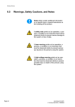
siskiyou An Oregon Corporation Motion Controller User’s Manual MC1000e-R / T © 2013 by Siskiyou Corporation MC1000e-R / T User’s Manual Service Information Non-Warranty Repairs Please call, email, or fax in your questions to Siskiyou Corporation at: Telephone (toll free): 1-877-313-6418 E-Mail: [email protected] Facsimile: 1-541-479-3314 If a product needs repairing after the one year warranty period expires, we will first provide an estimate of repair charges and then repair the product upon receiving authorization from you. Repairs are warranted for 90 days. Refer to the above Warranty Repairs information for return procedures. For a mailing address, refer to page 11. Table of Contents Product Warranty Siskiyou Corporation products carry the following warranty, effective for a period of one year from the original invoice date unless otherwise stated in the product literature: n Siskiyou Corporation products will be free of defects in material and workmanship. n Siskiyou Corporation products will meet the specifications stated in this catalog. If you find any defects in material or workmanship, or a failure to meet specifications within the warranty period, return the product to us clearly marked with a Return Authorization (RA) number and we will either repair or replace it at our discretion. Call our toll free telephone number and ask for the service department to request RA numbers. Our warranty excludes products that have been improperly installed or maintained, modified or misused. Notification of claim must occur within the warranty period. Siskiyou Corporation’s liabilities are limited as set forth in our STANDARD TERMS AND CONDITIONS, copies of which are available upon request. Siskiyou Corporation products unused and undamaged may be returned to Siskiyou Corporation within 30 days of the initial invoice date (60 days outside of the US), but are subject to a 25% restocking fee. Section 1.0 - Introduction 3 Section 1.1 - Inspection 3 Section 1.2 - Performance Specifications 3 Section 2.0 - Description 3 Section 3.0 - Installation 4 Section 4.0 - Interface 5 Section 4.1 - Junction Box 5 Section 4.2 - Controller 5 Section 5.0 - Operatiion 6 Section 6.0 - Troubleshooting 7 Section 7.0 - Maintenance and Service 7 Related Products 8 Warranty Repairs Before shipping a part to Siskiyou Corporation, a Return Authorization (RA) number must be obtained by calling our service department at our toll free telephone number. The product must be shipped prepaid in the original or equivalent packing with the RA number clearly marked on the outside of the box. Pack carefully to prevent damage. Place actuators, stages, manipulators, and controllers in a clean plastic bag to prevent contamination from packing materials. Siskiyou Corporation cannot be responsible for any damage occurring in transit to us. Products are not accepted without a Return Authorization number on the outside of the shipping carton. Service Form SF9 Contact Information 11 List of Figures Figure 1: Interface 4 Copyright © 2013 Siskiyou Corporation. All rights reserved. No part of this catalog may be reproduced, copied or transmitted in any form or by any means electronic or mechanical, including photocopying, recording, taping, or by an information storage and retrieval system, in English or in other languages, without written permission from the publisher. 2 www.siskiyou.com siskiyou1-877-313-6418 MC1000e-R / T User’s Manual 1.0 Introduction 209 This manual describes the operation of Siskiyou’s Model MC1000e-R / T micromanipulator motion controller. 1.1 Inspection Siskiyou products are shipped in sturdy, cushioned boxes. Please inspect the instrument immediately and notify the carrier if damage is obvious. MC1000e-R/T.eps 2 2.0 Description MC1000e-R / T The MC1000e-R/T 4-axis dial controller acts as a remote micrometer control with a user selected target feature for 800 and 7000 series actuators, manipulators, and stages. The MC1000e-R/T uses encoder feedback from our closed loop devices to create an electronic link between the controller dial and the device being driven. This direct coupling to the encoder ensures smooth and coordinated motion between the controller and the drive. The encoder coupling enables the use of the DR1000 digital readout for repeated positioning requirements. A two-position rocker switch is conveniently located on the side of the controller to allow for rapid and slow travel speed. The rapid setting is set to maximize speed (1.5 mm/second) when the dial is turned at 240 RPM. The slow setting is set to maximize resolution (0.2 µm) but still allow coarse positioning (45 µm/second). The TARGET/RETRACT allows the user to set a target location at a desired point. When it becomes necessary to back away from the experiment area, the user simply depresses the RETRACT button on the controller. The stage/actuator plugged into that axis (No.1), then automatically retracts to its full negative limit. The user can then return to the previously set position by simply depressing the TARGET button. The MC1000e-R/T uses a universal switching power supply adapter as its source for clean DC power. All cables are shielded and a central ground lug is located on the junction box to ensure noise-free operation during sensitive electrophysiology experiments. 1-877-313-6418 CERTIFIED DEVICE 1.2 Performance Specifications Minimum controllable motion Maximum speed 0.2 µm 1.5 mm/sec at 240 RPM Power requirements 110–230 VAC, 50/60 Hz via included power supply adapter Output 18 VDC / 2.5 A siskiyouwww.siskiyou.com 3 MC1000e-R / T User’s Manual 2 7021000s.eps MC1000e-R / T Setup Instructions ER AP AD R TE Drive axis no.4 W PO ! BB-5.0 construction rail and hardware used for mounting control and junction boxes, if needed. 4 screws provided, BB-5.0 purchased separately. IMPORTANT: Make sure all connectors are securely plugged in before power is turned on. Drive axis no.3 25 pin D connector for motorized drive, 4 places PO WER PO WER Power switch ON IN CO NTRO LLER 1 Low / High speed switch Drive axis no.1 2 1 3 2 4 3 MC 1000 (COM e- PATI R/T BLE CO WIT N H 76 TRO :1 GE LL ARHE ER AD) 4 Drive axis no.2 Reverse polarity switches, 4 places siskiyou The motor/gearhead ID tag on each motorized drive and motorized stage shows the gearhead ratio. See example: 1524-76:1-15/8 The junction box lid has been marked to indicate the correct motor/gearhead type to be used with this controller. Figure 1: Interface 3.0 Installation ! CAUTION: MAKE SURE ALL CONNECTORS ARE SECURELY PLUGGED IN BEFORE POWER IS TURNED ON. DO NOT REMOVE CONNECTORS WHILE POWER IS ON. FAILURE TO DO SO CAN RESULT IN A SHORT CIRCUIT AND PERMANENT DAMAGE TO THE SYSTEM. To install the MC1000e-R/T, please refer to Figure 1: Interface or the supplied set up instructions. Supplied with the MC1000e-R/T are two ¼-20 screws that can be used in securing both the controller and the junction box to the work station. * 4 www.siskiyou.com It is advised to align Drive Axis No.3 of the controller towards the user. In doing so, Drive Axis No. 1, 2, 3 and 4 are aligned respectively with the tilt, X, Y, and Z axes. Each axis is label on the controller by a number. It is also advised to add a ground wire onto the junction box and attach the free end of the wire to a metal surface outside of the system. The lug to use is labeled by the electrical symbol for “ground”: siskiyou1-877-313-6418 MC1000e-R / T User’s Manual 2 4.0 Interface 2 4.1 Junction Box Junction Box. eps Power In: Using the supplied power adapter, the user can connect the power adapter to the junction box and supply power to the system. Power Switch: The power switch turns on the junction box and the controller. This is required to be on in order to use the MC1000e-R/T. Turning off the power switch will cease all operations with manipulators remaining in place. The same applies to loss of power. Ground: By attaching a wire from the ground lug to a metal surface (that is not part of the experimental system), the user helps prevent damage from static shock and to ensure noise-free operation while in use. The lug is represented by the electrical symbol for “ground”: MC1000e-R/T Junction Box Controller: The 25 pin, male connector, is used for connecting the controller to the junction box. Only use the supplied cable for this connection. Controller.eps 1, 2, 3, and 4 Ports: The 25 pin, female connectors, are used for connecting the motor drive cables to the junction box. A motor drive must be plugged into port 1 for the MC1000e-R/T to work. TARGET ~ press to return Drive 1 to the target position • TARGET SET~ 2 press to save location 4.2 Controller ! CAUTION: MAKE SURE THAT THE FOLLOWING STEPS OF INSTRUCTIONS CONCERNING TARGET SET, RETRACT, AND TARGET BUTTON FEATURES ARE FOLLOWED TO AVOID AN UNWANTED COLLISION TO YOUR SETUP. RETRACT~ press to return Drive 1 to the rear of travel Drive Axis No. 1, 2, 3, and 4: These four knobs are color coded for easier identification for the user and each axis is label with a 1, 2, 3, or 4. When the controller is plugged into the junction box, drive axes 1, 2, 3, and 4 control the respective axis that is plugged into the junction box. MC1000e-R/T Controller TARGET SET: This in the red push button that is located in front of Drive Axis No.1 and only affects axis 1. Power adapter MC1000.eps When the user has found a reference position that they would like to automati cally return to, the user can push this button and the location will be saved. A green LED will become illuminated when this button is pressed.. ER W PO TE AP AD RETRACT: This is a black push button that is located in front of Drive Axis R No.1 and only affects axis 1. After the user has pressed the red “Target Set” button that creates the desired HOME position to have the axis 1 return to, the user can press the “Retract” button and the axis 1 motor drive will move to the rear of travel. Axes 2, 3, and 4 will still be able to move in this retracted mode. The user will need to be cautious not to turn any dials for Drive No. 2, 3, or 4 as doing so will result in a change in the micromanipulator stage position. A red LED will illuminate when the motor drive is in this position. 1-877-313-6418 Generic Power Adapter siskiyouwww.siskiyou.com 5 MC1000e-R / T User’s Manual 4.2 Controller continued TARGET: This is a black push button that is located in front of Drive Axis No.1 and only affects axis 1. When a target is set, and the user has pressed the RETRACT button, the user can press the TARGET button, and the motor drive will return to the targeted position. A green LED will become illuminated when the motor drive has reached the targeted position. This feature will only work when the drive axis is retracted. Low/High Speed: The low/high speed switch is located on the back of the controlled and is labeled with a rabbit on one side, and a turtle on the opposite. When the switch is toward the turtle, the motor drive will move at a slower rate per turn on the drive axis. When the switch is facing the rabbit, the motor drive will move at a faster rate per turn on the drive axis. 25 Pin Connector: This connection port is used to connect the controller to the junction box. Only use the supplied cable for this connection. Reverse Polarity: On the back of the controller are four toggle switches that are labeled 1 through 4 that correspond to the respective drive axes. By switching one of the toggle switches, the user is able to change the direction the motor drive travels while still rotating the drive axis in the same direction. 5.0 Operation When the MC1000e-R/T has been correctly installed, the user can begin use of the system. The operation may be bench tested prior to installing the unit to an experiment. When the user rotates one of the drive axis knobs, the motor drive that is plugged into the respective port will also move. For example, if the tilt axis is plugged into port 1, when Drive Axis No.1 is rotated, the tilt axis will move. The targeting axis is set to Drive Axis No.1. To set a point of reference when axis 1 is in a desired position, push the TARGET SET button. To retract the motorized axis 1, push the RETRACT button. Once the axis has reached its reverse limit switch, the red LED will light up. To bring the axis back to the target position, push the TARGET button. When the green LED lights up, the motorized axis is in the target position. ! 6 www.siskiyou.com For best results and to avoid backlash, the direction of travel when the target set button is pushed should be a forward move. This is the same travel direction as the movement from the limit switch to the target. Avoid turning on the dials during the targeting operation, as this may cause the stage to “jump” when the targeted position has been reached. siskiyou1-877-313-6418 2 MC1000e-R / T User’s Manual 2 6.0 Troubleshooting Axis 1 is retracted and I accidently hit the TARGET SET button and now either axes 2, 3, and 4 do not work, or nothing will work. Typically, with our lab testing, if axis 1 is retracted, and the TARGET SET button is pressed (which creates a new target position at the retracted position, where both LEDs light up), axis 1 will still move while axes 2, 3, and 4 will not. However, if multiple “random” button pressing occurs during this scenario, it will cause a full system lockup. In order to recover from the lockup, the system will need to be powered off by pressing the power button on the junction box. Once off, the user can then turn the system back on. By manually moving axis 1 out of the retracted position, the user can then hit the TARGET SET button to create a new target position. Axes 2, 3, and 4 will now work. Be careful not to hit additional buttons before axis 1 has been moved after the power is reapplied. Doing so may cause an additional system lockup. I accidently hit the RETRACT button, is there any way to stop it? While in automatic motion, either in retract or target mode, none of the drive axis controllers will work. If the RETRACT button is accidently pressed, the user can turn off the system by pressing the power button on the junction box. This will stop all motion. The user can then manually place the drive motor back into position. However, it may be best to let the system finish the retract function. Once retracted, the user can press the TARGET button to return to the previous target. The system was turned off. Will I still have my previous target? Yes. The system has an onboard memory that stores the location of the last target used on axis 1. By placing the drive axis in the retracted mode, the user can press the TARGET button to return to the previous target. It is recommended to not move axes 2, 3, or 4 as doing so can change the target location of axis 1. Note: Due to the programming capabilities of the unit, this feature will not work initially on power up if axis 1 is in the retracted mode (red LED is on). By moving the axis out of the retracted mode (red LED is off), the user can then hit the RETRACT button and then the TARGET button to return to the previous target. Drive Axis 1 is against the forward limit switch and now axes 2, 3, and 4 will not work. This feature is programmed into the MC1000e-R/T. While against the forward limit switch, axes 2, 3, and 4 will not work. However, the RETRACT button can be pressed to retract the drive axis as well as manually moving axis 1 off of the forward limit switch. Once out of the forward position, the user can continue with the test as axes 2, 3, and 4 will now work. 2 7.0 Maintenance and Service There are no user servicable parts inside the controller or junction box. In the event of the need for service, call Siskiyou Corporation and have the information as shown on the Service Form (page 7) ready to discuss with a technician. 1-877-313-6418 * If the problem cannot be solved through telephone or email communication, an RA number will be provided to return the unit to Siskiyou Corporation. Submit a copy of the service form with the unit. siskiyouwww.siskiyou.com 7 MC1000e-R / T User’s Manual Related Products Switching Box A37 ABCD switching box allows control of one to four 4‑axis micromanipulators by one controller (MC2000 excluded). The basis of the design is simple and requires only an extra controller junction box for each added micromanipulator or motor drive group (up to four per group). Junction boxes must be purchased separately. SB-MC1000e Series Digital Readout 202 The DR1000 Digital Readout provides an accurate, highly visible display for axis position. The digital readout may be installed on any of our e series controllers and is connected in series via a double-sided connector between the controller junction box and the device D connector. DR1000 518 8 www.siskiyou.com siskiyou1-877-313-6418 Service Form Return a copy of this form along with the product to Siskiyou Corporation 2 PRODUCT CONTACT Company ________________________________________ Return Authorization No. ______________________________ Note: Call the toll free number prior to returning the item. Address ________________________________________ City, St Zip ________________________________________ Date ______________________________________________ Country Technical Contact ____________________________________ ________________________________________ Sales Order ________________________________________Telephone __________________________________________ PO Number ________________________________________ Fax _______________________________________________ Purchase Date _____________________________________ Email ���������������������������������������������� Model Number ______________________________________ Serial Number _______________________________________ Describe any modifications made to the unit _____________________________________________________________________ ______________________________________________________________________________________________ ______________________________________________________________________________________________ RETURN TO REASON FOR RETURN List all control settings and describe problems __________________________________________________________________ _____________________________________________________________________________________________ _____________________________________________________________________________________________ _____________________________________________________________________________________________ _____________________________________________________________________________________________ Diagram Email addresses: [email protected] [email protected] [email protected] Website: www.siskiyou.com Toll free 1-877-313-6418 Siskiyou Corporation RA# _________________ 110 S.W. Booth Street Grants Pass, OR 97526-2410 U.S.A. siskiyou SF9 RA Number must be clearly written on the outside of the shipping carton Fax 1-541-479-3314 MC1000e-R / T User’s Manual BLANK 10 www.siskiyou.com siskiyou1-877-313-6418 MC1000e-R / T User’s Manual 2 Contact Information Washington 2 Portland Salem Eugene OREGON Idaho Pacific Ocean INTERSTATE 5 Grants Pass Mailing Address Siskiyou Corporation 110 S.W. Booth Street Grants Pass, OR 97526-2410 TS. SISKIYOU M California Nevada Oregon-7.eps Sales and Service [email protected] [email protected] telephone (toll free): 1-877-313-6418 Technical Assistance [email protected] telephone: 1-541-479-8697 facsimile: 1-541-479-3314 Website www.siskiyou.com [email protected] International Please call or visit our website for international contacts. All dimensions in this manual are given in inches unless specified otherwise. Printed 04/30/03 1-877-313-6418 Document No. MC1000e-R/T0613 Printed in the U.S.A. Photos by Robert Jaffe email [email protected] siskiyouwww.siskiyou.com 11 Siskiyou Corporation 110 SW Booth Street Grants Pass, OR 97526-2410 Telephone541-479-8697 Toll-Free877-313-6418 Facsimile541-479-3314 Websitewww.siskiyou.com