1
B8976101/01
AS-i Master Module CP 342-2
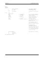
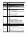
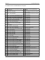
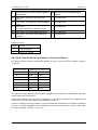
Example of the assignment of connections
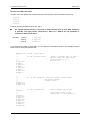
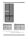
If AS-i modules are used as slaves on the AS-i cable, each of the connections to the AS-i module
corresponds to exactly 1 bit in the PLC. The following example illustrates the assignment of two AS-i
modules with addresses 2 and 3.
Slave 2
Slave 3
PLC bit
7
6
5
4
3
2
1
0
Connection to AS-i
module
4
3
2
1
4
3
2
1
Table 3-2
PLC I/O bits
Assignment of the Connections to the AS-i Module
Explanation:
Slave 2 corresponds, in this case, to the AS-i module with address 2
Slave 3 corresponds to the AS-i module with address 3.
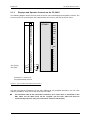
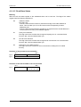
Example of the PLC Addressing a Slave
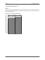
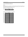
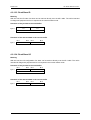
Just as with standard modules of the analog I/Os, the S7-300 can access the inputs and outputs of
the AS-i slaves. The following example illustrates this procedure:
Example: CP 342-2 with start address n = 256
Start
address 256
256
257
258
.
.
.
S7 - 300
S lav e 1
reserved
Bit 3
Slave 2
Bit 3
Bit 2
Bit 1
Bit 0
Bit 2
Bit 1
Bit 0
Bit 3
Bit 3
Bit 2
Bit 1
Bit 0
Bit
Bit33
7
6
5
4
3
I/O byte no.
Bit 0
Bit 1
Bit 0
Bit 1
Bit 0
Slave
S l av e 31
Bit
31BitBit22
Bit 11
Bit
Bit00
Bit 2
Slave 5
Slave 30
271
Bit 1
Bit 3
Slave 4
Bit 3
Bit 2
Slave 3
Bit 2
2
1
0
I/O bit no.
A S-i slav es
Slave no. 2
Slave no. 3
Slave no. 4
I/O code= 9H
I/O code= EH
I/O code= 8H
Slave no. 31
( AS-I module )
I/O code= 0H
Bit 3
Bit 2
Bit 1
Bit 0
Bit 3
Bit 2
Bit 1
Bit 0
Bit 3
Bit 2
Bit 1
Bit 0
Bit 3
Bit 2
Bit 1
Bit 0
Connection
Used
al as
usgang
output
be u
used as
als Ausgang
output
ben
Connection
Used as
input
1 A S - i m o du le
2 A S-i m odul e
used as
output
Connection
bidirectional
Connection
Figure 3-1 Mapping the Slave Addresses on the I/O Addresses
3-5
3 A S - i m o du l e
4 A S -i m o du l e