1
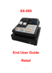
HP 8924C CDMA Mobile Station Test Set
Application Guide
Firmware Version A.06.25 and above
CDMA CALL CONTROL
CALL
ANS
END
CALL
FUNCTIONS
INSTRUMENT STATE
MSG
PRINTER
I/O CONFIG
CONFIG
ADRS
SAVE
HOLD
HELP
PRINT
PREV
TESTS
LOCAL
RECALL
MEAS
RESET
PRESET
MEMOR
Y CARD
USER
k1’
CDMA SCRNS
CELL
RANGE
REF SET
METER
AVG
INCR
SET
INCR X10
k1
CALL
CTRL
RX
TEST
INCR
: 10
k2’
SPECTRUM
MSRPT
LO LIMIT
k2
GEN
CTRL
TX
TEST
ANALOG SCRNS
ASSIGN
ENCODER
DECODER
k4
RF
ANL
RX
TEST
AF
ANL
TX
TEST
RELEASE
k5
SHIFT
SCOPE
RF
GEN
DUPLEX
MIC/ACC
8
9
ENTER
4
5
6
GHz
dBm
1
2
3
MHz
V
+ _
kHz
mV
dB
CURSOR
CONTROL
PUSH TO
SELECT
%
s
ACP
SPEC ANL
7
HI LIMIT
k3’
k3
DATA
DATA FUNCTIONS
0
CANCEL
VOLUME
SQUELCH
YES
NO
Ω
ms
ON/OFF
ppm
W
%
dBµV
Hz
µV
AUDIO OUT
AUDIO IN
HI
POWER
LO
!
!
MAX PWR
MAX PWR
200 mW
6W
!
DO NOT APPLY
RF WHEN OFF
RF IN/OUT
DUPLEX OUT
ANTENNA IN
!
MAX
12 v Pk
!
MAX
42 v Pk
HP Part No. 08924-90021
Printed in U. S. A.
December 1998
Rev. G
1
Copyright © Hewlett-Packard Company 1995
Notice
Information contained in this document is subject to change without notice.
All Rights Reserved. Reproduction, adaptation, or translation without prior written
permission is prohibited, except as allowed under the copyright laws.
This material may be reproduced by or for the U.S. Government pursuant to the
Copyright License under the clause at DFARS 52.227-7013 (APR 1988).
Hewlett-Packard Company
Learning Products Department
24001 E. Mission
Liberty Lake, WA 99019-9599
U.S.A.
2
Manufacturer’s Declaration
This statement is provided to comply with the requirements of
the German Sound Emission Directive, from 18 January 1991.
This product has a sound pressure emission (at the operator
position) < 70 dB(A).
•
•
•
•
Sound Pressure Lp < 70 dB(A).
At Operator Position.
Normal Operation.
According to ISO 7779:1988/EN 27779:1991 (Type Test).
Herstellerbescheinigung
Diese Information steht im Zusammenhang mit den Anforderungen der
Maschinenlärminformationsverordnung vom 18 Januar 1991.
•
•
•
•
Schalldruckpegel Lp < 70 dB(A).
Am Arbeitsplatz.
Normaler Betrieb.
Nach ISO 7779:1988/EN 27779:1991 (Typprüfung).
3
Safety
Considerations
GENERAL
This product and related documentation must be reviewed for familiarization with
safety markings and instructions before operation.
This product has been designed and tested in accordance with IEC Publication
1010, "Safety Requirements for Electronic Measuring Apparatus," and has been
supplied in a safe condition. This instruction documentation contains information
and warnings which must be followed by the user to ensure safe operation and to
maintain the product in a safe condition.
SAFETY EARTH GROUND
A uninterruptible safety earth ground must be provided from the main power
source to the product input wiring terminals, power cord, or supplied power cord
set.
CHASSIS GROUND TERMINAL
To prevent a potential shock hazard, always connect the rear-panel chassis ground
terminal to earth ground when operating this instrument from a dc power source.
SAFETY SYMBOLS
!
Indicates instrument damage can occur if indicated operating limits are exceeded.
Indicates hazardous voltages.
Indicates earth (ground) terminal
WARNING
A WARNING note denotes a hazard. It calls attention to a procedure,
practice, or the like, which, if not correctly performed or adhered to, could
result in personal injury. Do not proceed beyond a WARNING sign until the
indicated conditions are fully understood and met.
CAUTION
A CAUTION note denotes a hazard. It calls attention to an operation procedure,
practice, or the like, which, if not correctly performed or adhered to, could result
in damage to or destruction of part or all of the product. Do not proceed beyond
an CAUTION note until the indicated conditions are fully understood and met.
4
Safety Considerations for this Instrument
WARNING
This product is a Safety Class I instrument (provided with a protective
earthing ground incorporated in the power cord). The mains plug shall only
be inserted in a socket outlet provided with a protective earth contact. Any
interruption of the protective conductor inside or outside of the product is
likely to make the product dangerous. Intentional interruption is
prohibited..
Whenever it is likely that the protection has been impaired, the instrument
must be made inoperative and be secured against any unintended operation.
If this instrument is to be energized via an autotransformer (for voltage
reduction), make sure the common terminal is connected to the earth
terminal of the power source.
If this product is not used as specified, the protection provided by the
equipment could be impaired. This product must be used in a normal
condition (in which all means for protection are intact) only.
No operator serviceable parts in this product. Refer servicing to qualified
personnel. To prevent electrical shock, do not remove covers.
Servicing instructions are for use by qualified personnel only. To avoid
electrical shock, do not perform any servicing unless you are qualified to do
so.
The opening of covers or removal of parts is likely to expose dangerous
voltages. Disconnect the product from all voltage sources while it is being
opened.
Adjustments described in the manual are performed with power supplied to
the instrument while protective covers are removed. Energy available at
many points may, if contacted, result in personal injury.
The power cord is connected to internal capacitors that my remain live for
5 seconds after disconnecting the plug from its power supply.
For Continued protection against fire hazard, replace the line fuse(s) only
with 250 V fuse(s) or the same current rating and type (for example, normal
blow or time delay). Do not use repaired fuses or short circuited
fuseholders.
5
CAUTION:
Always use the three-prong ac power cord supplied with this product. Failure to ensure
adequate earth grounding by not using this cord may cause product damage.
This product is designed for use in Installation Category II and Pollution Degree
2 per IEC 1010 and IEC 664 respectively.
This product has autoranging line voltage input, be sure the supply voltage is
within the specified range.
Ventilation Requirements: When installing the product in a cabinet, the
convection into and out of the product must not be restricted. The ambient
temperature (outside the cabinet) must be less than the maximum operating
temperature of the product by 4° C for every 100 watts dissipated in the cabinet.
If the total power dissipated in the cabinet is greater than 800 watts, then forced
convection must be used.
Product
Markings
CE - the CE mark is a registered trademark of the European Community. A CE
mark accompanied by a year indicated the year the design was proven.
CSA - the CSA mark is a registered trademark of the Canadian Standards
Association.
6
CERTIFICATION
Hewlett-Packard Company certifies that this product met its published
specifications at the time of shipment from the factory. Hewlett-Packard further
certifies that its calibration measurements are traceable to the United States
National Institute of Standards and Technology, to the extent allowed by the
Institute’s calibration facility, and to the calibration facilities of other
International Standards Organization members
WARRANTY
This Hewlett-Packard instrument product in warranted against defects in material
and workmanship for a period of one year from date of shipment. During the
warranty period, Hewlett-Packard Company will at its option, either repair or
replace products which prove to be defective.
For warranty service or repair, this product must be returned to a service facility
designated by HP. Buyer shall prepay shipping charges to HP and HP shall pay
shipping charges, duties, and taxes for products returned to HP from another
country.
HP warrants that its software and firmware designated by HP for use with an
instrument will execute its programming instructions when properly installed on
that instrument. HP does not warrant that the operation of the instrument, or
software, or firmware will be uninterrupted or error free.
LIMITATION OF
WARRANTY
The foregoing warranty shall not apply to defects resulting from improper or
inadequate maintenance by Buyer, Buyer-supplied software or interfacing,
unauthorized modification or misuse, operation outside of the environmental
specifications for the product, or improper site preparation or maintenance.
NO OTHER WARRANTY IS EXPRESSED OR IMPLIED. HP SPECIFICALLY
DISCLAIMS THE IMPLIED WARRANTIES OF MERCHANTABILITY AND
FITNESS FOR A PARTIDCULAR PURPOSE.
EXCLUSIVE
REMEDIES
THE REMEDIES PROVIDED HEREIN ARE BUYER’S SOLE AND
EXCLUSIVE REMEDIES. HP SHALL NOT BE LIABLE FOR ANY DIRECT,
INDIRECT, SPECIAL, INCIDENTAL, OR CONSEQUENTIAL DAMAGES,
WHETHER BASE ON CONTRACT, TORT, OR ANY OTHER LEGAL
THEORY.
ASSISTANCE
Product maintenance agreements and other customer assistance agreements are
available for Hewlett-Packard products. For any assistance, contact your nearest
Hewlett-Packard Sales and Service Office.
7
DECLARATION OF CONFORMITY
according to ISO/IEC Guide 22 and EN 45014
Manufacturer’s Name:
Hewlett-Packard Co.
Manufacturer’s Address:
Spokane Division
24001 E. Mission Avenue
Liberty Lake, Washington 99019-9599
USA
declares that the product
Product Name:
CDMA Mobile Station Test Set
Model Number:
HP 8924C
Product Options:
This declaration covers all options of the above
product.
conforms to the following Product specifications:
Safety: IEC 1010-1:1990+A1 / EN 61010-1:1993
EMC:
CISPR 11:1990/EN 55011:1991- Group 1, Class A
EN 50082-1 : 1992
IEC 801-2:1991 - 4kV CD,8kV AD
IEC 801-3:1984 3V/m
IEC 801-4:1988 0.5 kV Sig. Lines, 1 kV Power Lines
Supplementary Information:
This product herewith complies with the requirements of the Low Voltage Directive
73/23/EEC and the EMC Directive 89/336/EEC and carries the CE-marking
accordingly.
Spokane, Washington USA
October 17, 1996
Vince Roland
Reliability & Regulatory
Engineering Manager
European Contact: Your local Hewlett-Packard Sales and Service Office or Hewlett-Packard GmbH
Department ZQ/Standards Europe, Herrenberger Strasse 130, D-71034 Böblinger, Germany (FAX+49-7031-14-3143)
8
Table of Contents
Contents
1 Calibrating the Test Set
Calibration Procedures 24
Guidelines: 24
Recommended Calibration Procedures:
25
Calibrating CDMA Channel Levels 26
Calibrating Channel Power Measurements 29
Procedure Overview 33
Calibrating RF Generator Levels 35
Zeroing Average Power Measurements 36
Procedure Overview 40
Correcting for RF Path Loss 41
Determining RF Path Loss 44
Procedure Prerequisites 44
Procedure Overview 50
N:\mkt\MANUALS\HP8924C\APPMOD\BOOK\APPMOD.TOC
9
Contents
2 Setting Up a Call
Setting up a Call 52
Procedure Overview 66
Problem Solving 68
Checklist 1. MSUT did not find service 68
Checklist 2. Registration failed 70
10
N:\mkt\MANUALS\HP8924C\APPMOD\BOOK\APPMOD.TOC
Table of Contents
Contents
3 CDMA Receiver Tests
List of CDMA Receiver Tests 72
Measuring Demodulation of Forward Traffic Channel with
AWGN 73
Test Prerequisites 73
Measurement Overview 82
HPBASIC Programming Example
83
Measuring Receiver Sensitivity and Dynamic Range 87
Measurement Overview 95
HPBASIC Programming Example
96
Measuring Single Tone Desensitization 99
Test Prerequisites 99
Recommended Equipment 99
Measurement Overview 110
Programming Example 111
Measuring Intermodulation Spurious Response Attenuation 115
Test Prerequisites 115
Recommended Equipment 115
Measurement Overview 126
Measuring Demodulation of Non-Slotted Mode Paging Channel in
AWGN 128
Test Prerequisites 128
Measurement Overview 136
N:\mkt\MANUALS\HP8924C\APPMOD\BOOK\APPMOD.TOC
11
Contents
4 CDMA Transmitter Tests
List of CDMA Transmitter Tests 140
Measuring Waveform Quality 141
Measurement Overview 147
HPBASIC Program Example 148
Measuring Minimum/Maximum Power 150
Test Prerequisites 150
Measurement Overview 153
Measuring Maximum RF Output Power 154
Test Prerequisites 154
Measurement Overview 161
HPBASIC Programming Example
162
Measuring Minimum Controlled Output Power 164
Test Prerequisites 164
Measurement Overview 171
HPBASIC Programming Example
172
Measuring the Range of Open Loop Output Power 175
Test Prerequisites 175
Measurement Overview 183
HPBASIC Programming Example
184
Measuring Access Probe Output Power 186
Test Prerequisites 186
Recommended Equipment 186
Measurement Overview 195
HPBASIC Programming Example
12
196
N:\mkt\MANUALS\HP8924C\APPMOD\BOOK\APPMOD.TOC
Table of Contents
Contents
5 CDMA to Analog Handoff
Performing a CDMA to Analog Handoff 200
HP BASIC Example 208
Procedure Overview 209
N:\mkt\MANUALS\HP8924C\APPMOD\BOOK\APPMOD.TOC
13
Contents
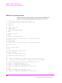
6 Authentication Tests
List of CDMA Authentication Tests 212
Initializing SSD to Zero 213
Measurement Overview 221
Updating SSD 222
Measurement Overview 229
Performing a Unique Challenge-Response 230
Measurement Overview 237
14
N:\mkt\MANUALS\HP8924C\APPMOD\BOOK\APPMOD.TOC
Table of Contents
Contents
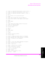
7 Short Message Service Tests
List of CDMA SMS Tests 240
Sending Short Messages on the Paging/Access Channels 241
Measurement Overview 249
Sending Short Messages on the Traffic Channels 250
Measurement Overview 258
N:\mkt\MANUALS\HP8924C\APPMOD\BOOK\APPMOD.TOC
15
Contents
8 Establishing HP-IB Communication
Setting Up HP-IB Control 260
16
N:\mkt\MANUALS\HP8924C\APPMOD\BOOK\APPMOD.TOC
Table of Contents
Contents
9 264 Using the Analog Call Processing Subsystem
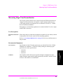
Description of the Analog Call Processing Subsystem 264
Operational Overview 265
Accessing the Analog Call Processing Subsystem Screens 267
Analog Call Processing Subsystem Screens 267
Using Manual (Front-Panel) Control 268
Connecting A Mobile Station 268
Mobile Station Audio Out Impedance 270
Generalized Test Procedure 270
Description of the Call Processing Subsystem’s Remote User
Interface 275
Operational Overview 276
Using Remote (HP-IB) Control 277
Accessing the Call Processing Subsystem Screens 277
Command Syntax 278
Conditioning the Test Set for Call Processing 279
Analog Call Processing Subsystem HP-IB Error Messages 280
Reading An Analog Call Processing Subsystem HP-IB Error Messages 280
Call Processing Status Register Group 281
Using the Call Processing Status Register Group To Control Program Flow 281
When To Query Data Messages Received From The Mobile Station 282
Using the CALL CONTROL Screen to Test Call Processing
Functions 285
Conditioning the Test Set for Call Processing 285
Configure the Test Set 286
Turn On The Test Set’s Control Channel 287
Register a Mobile Station 287
Page a Mobile Station 288
Handoff a Mobile Station to a New Voice Channel 289
Release A Mobile Station 289
Change the Transmit Power Level of a Mobile Station 290
Originate a Call from a Mobile Station 290
Send an Alert Order to a Mobile Station 291
N:\mkt\MANUALS\HP8924C\APPMOD\BOOK\APPMOD.TOC
17
Contents
Using the CALL CONTROL Screen to test AMPS
Authentication 292
Condition the Test Set for Call Processing 292
Configure the Test Set 293
Turn on the Test Set’s Control Channel 294
Initialize Call Processing with Authentication 294
Page a Mobile Station with Authentication 296
Originate a Call with Authentication 296
Perform an SSD Update 297
Perform a Unique Challenge 299
Using the CALL DATA Screen 301
To View the Decoded Reverse Channel Words from a Mobile Station Page 302
To View the Decoded Reverse Channel Words From a Mobile Station
Handoff 304
To View the Decoded Reverse Channel Words from a Mobile Station
Release 305
To View the Decoded Reverse Channel Words from an Order to Change the Transmit Power Level of a Mobile Station 306
To View The Reverse Channel Words From a Mobile Station Origination 307
Using the CALL BIT Screen 308
Selecting The Message Content Generation Method 308
System Operation When Data Spec Field Set to Std 309
System Operation When Data Spec Field Set to Bits 310
Changing the Content of a Message Field 311
Typical Example 311
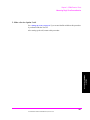
Using the ANALOG MEAS Screen 313
To Make an RF Sensitivity Measurement 313
To Make an FM Hum and Noise Measurement 314
18
N:\mkt\MANUALS\HP8924C\APPMOD\BOOK\APPMOD.TOC
Table of Contents
Contents
10 Controlling Program Flow
Using Service Request (SRQ) Interrupts 318
Controlling Program Flow Procedure 319
Examples Used in this Procedure 319
Example BASIC Program to Set Up and Service an SRQ Interrupt 328
N:\mkt\MANUALS\HP8924C\APPMOD\BOOK\APPMOD.TOC
19
Contents
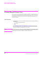
11 Protocol Logging
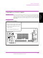
Hardware and Software Requirements 335
Hardware Requirements 335
Software Requirements 336
Connecting the Test Set to the Computer 337
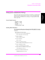
Setting Up the Communications Package 339
General Setup Parameters 339
Installing PROCOMM PLUS 339
Reconfiguring PROCOMM PLUS 340
Logging Protocol Messages 342
Capturing a Log to a File on the Computer
344
Control Commands for Protocol Logging 345
Logging Port 1 Commands 345
Logging Port 2 Commands 348
20
N:\mkt\MANUALS\HP8924C\APPMOD\BOOK\APPMOD.TOC
Table of Contents
Contents
Index 351
N:\mkt\MANUALS\HP8924C\APPMOD\BOOK\APPMOD.TOC
21
Contents
22
N:\mkt\MANUALS\HP8924C\APPMOD\BOOK\APPMOD.TOC
N:\mkt\MANUALS\HP8924C\APPMOD\BOOK\chapters\amcal.fb
Calibrating the Test Set
1
23
Chapter 1
Calibrating The Test Set
Chapter 1, Calibrating the Test Set
Calibration Procedures
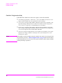
Calibration Procedures
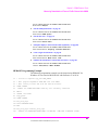
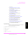
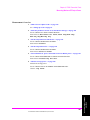
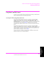
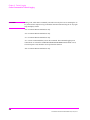
The list below shows all of the calibration procedures that must be performed
periodically when testing CDMA mobile stations with the Test Set, including
Test Sets configured with an HP 83236B PCS Interface.
"Calibrating CDMA Channel Levels" on page 26
"Calibrating Channel Power Measurements" on page 29.
"Calibrating RF Generator Levels" on page 35
"Zeroing Average Power Measurements" on page 36.
"Correcting for RF Path Loss" on page 41.
"Determining RF Path Loss" on page 44.
Guidelines:
"Recommended Calibration Procedures:" on page 25 provides a checklist of
calibration procedures for various events that could affect the performance of the Test Set.
Guidelines include:
•
•
•
After "Calibrating CDMA Channel Levels" on page 26 (also known as "PCB
CAL") is performed, you must then perform "Calibrating RF Generator Levels" on
page 35 and "Calibrating Channel Power Measurements" on page 29.
It is highly recommended that "Correcting for RF Path Loss" on page 41 be
performed before using the Test Set to make measurements. This procedure eliminates
the need for adding level offsets to your test code, and extends the Test Set’s operating
range with some mobile stations.
A 30-minute warm-up period is recommended to allow the Test Set to reach a stable
operating temperature.
24
N:\mkt\MANUALS\HP8924C\APPMOD\BOOK\chapters\amcal.fb
Chapter 1, Calibrating the Test Set
Calibration Procedures
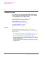
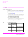
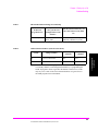
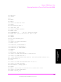
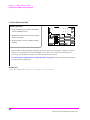
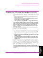
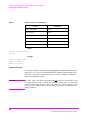
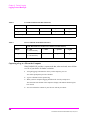
Recommended Calibration Procedures:
"Calibrating
Channel Power
Measurements"
on page 29
"Calibrating RF
Generator Levels"
on page 35
"Zeroing
Average Power
Measurements"
on page 36
Chapter 1
Calibrating The Test Set
"Calibrating
CDMA Channel
Levels" on page 26
(PCB CAL)
When Test Set is
being used for the
first time (allow
30-minute
warmup period).
After extended
power off cycle
(allow 30-minute
warmup period).
After firmware is
upgraded
When the "Uncal"
light is flashing
Before making an
Average Power
measurement
If the RF connections to the PCS
interface are
adjusted.
If the ambient
temperature
changes more than
5 degrees C since
latest calibration
Ram Initialization
Every month
25
N:\mkt\MANUALS\HP8924C\APPMOD\BOOK\chapters\amcal.fb
Chapter 1, Calibrating the Test Set
Calibrating CDMA Channel Levels
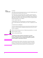
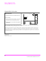
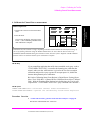
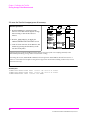
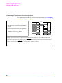
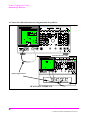
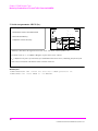
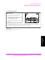
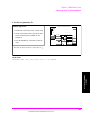
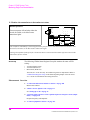
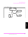
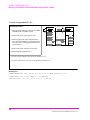
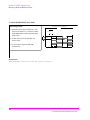
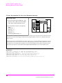
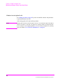
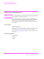
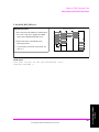
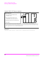
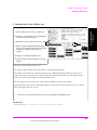
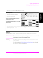
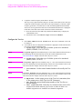
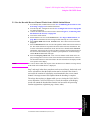
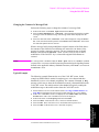
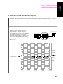
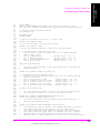
Calibrating CDMA Channel Levels
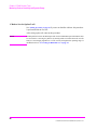
Approximate time: 8 minutes
CDMA channel levels should be calibrated whenever any of the following events
occur:
•
•
•
After a 30-minute warm-up period
After firmware is upgraded
If a 5° C change in ambient temperature occurs
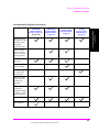
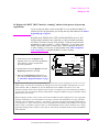
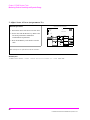
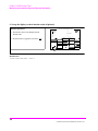
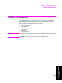
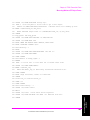
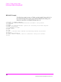
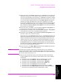
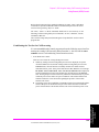
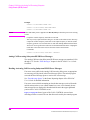
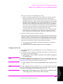
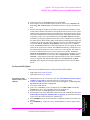
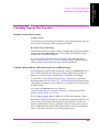
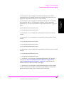
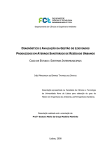
The Test Set optimizes the level accuracy of CDMA code channels and the
AWGN (Additive White Gaussian Noise) generator by measuring the analog I/Q
signals on an internal DSP-based voltmeter. Level correction factors are generated
by a ROM-based program named PCB_CAL and are applied to gain control
DACs, which control the fine level adjustment in the amplitude scaling path.
Calibrated channel power provides accurate values for Eb/Nt, the ratio between
Traffic channel power and AWGN. It is critical that these levels remain accurate.
A level accuracy error of 0.8 dB could alter FER from 0.5% to 5%.
Diagnostic Mux
AWGN
Analog I
Σ
Analog Q
Level Correction
Factors
To DSP
Voltmeter
I Output
Σ
Q Output
Gain Control
DAC
26
N:\mkt\MANUALS\HP8924C\APPMOD\BOOK\chapters\amcal.fb
Chapter 1, Calibrating the Test Set
Calibrating CDMA Channel Levels
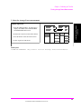
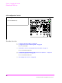
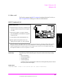
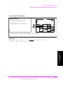
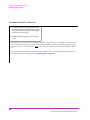
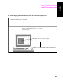
1. Load the PCB_CAL procedure.
Manual Operation:
TESTS (Main Menu)
Chapter 1
Calibrating The Test Set
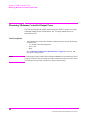
1. Press the TESTS key.
2. Select ROM from the list of choices for the
Select Procedure Location field.
Select Procedure Location:
ROM
Select Procedure Filename:
PCB_CAL
3. Select PCB_CAL from the list of choices for
the Select Procedure Filename field.
The TESTS (Main Menu) screen provides access to the Test Set’s internal IBASIC controller. You can load,
run, and customize procedures on this screen.
HP-IB Syntax
"DISP TEST" ! displays the TESTS (Main Menu) screen.
"TEST:PROC:LOC ’ROM’" ! selects ROM as the test procedure location.
"TEST:PROC:NAME ’PCB_CAL’" selects the file named "PCB_CAL"
27
N:\mkt\MANUALS\HP8924C\APPMOD\BOOK\chapters\amcal.fb
Chapter 1, Calibrating the Test Set
Calibrating CDMA Channel Levels
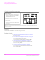
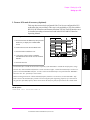
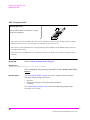
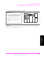
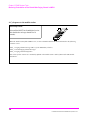
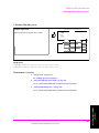
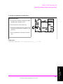
2. Run the PCB_CAL Procedure.
Manual Operation:
TESTS (Main Menu)
RUN TEST
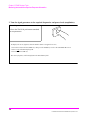
1. Position the cursor next to the Run Test field.
2.Press the knob.
Select Procedure Location:
ROM
Select Procedure Filename:
PCB_CAL
3. Follow instructions on the display. (You will be
instructed to remove all front-panel cables).
4. When the PCB_CAL procedure has completed,
cycle power.
At the beginning of the procedure, the Test Set will beep and the message "Direct latch write occurred. Cycle
power when done servicing" will appear. This is normal.
The PCB_CAL procedure will run for about 8 minutes. During this time the display will show cal factors for I
and Q channels on the screen.When the calibration procedure has completed, the message "Cycle instrument
power to restore test set to normal operating conditions" will be displayed at the top of the screen. At this point
you should cycle power.
HP-IB Syntax
"TEST:PROC:RUN"
28
N:\mkt\MANUALS\HP8924C\APPMOD\BOOK\chapters\amcal.fb
Chapter 1, Calibrating the Test Set
Calibrating Channel Power Measurements
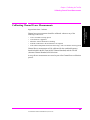
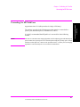
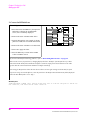
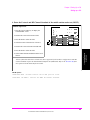
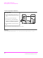
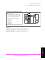
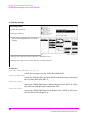
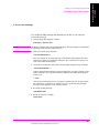
Calibrating Channel Power Measurements
Channel power measurements should be calibrated whenever any of the
following events occur:
•
•
•
•
•
After a 30-minute warm-up period
After firmware is upgraded
When the "Uncal" annunciator is flashing
If the RF connections to the PCS Interface are adjusted
If the ambient temperature drifts more than 5 deg C after a 30-minute warm-up period
Channel Power measurements will be calibrated for the combined frequency
bands included in the RF Chan Std (RF Channel Standard) and Alt Chn Std
(Alternate Channel Standard) field selections.
Average Power measurements are zeroed as part of the Channel Power calibration
process.
29
N:\mkt\MANUALS\HP8924C\APPMOD\BOOK\chapters\amcal.fb
Chapter 1
Calibrating The Test Set
Approximate time: 2 minutes
Chapter 1, Calibrating the Test Set
Calibrating Channel Power Measurements
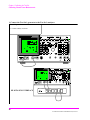
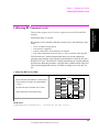
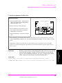
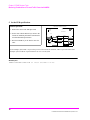
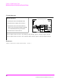
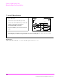
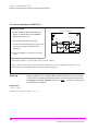
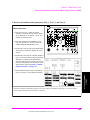
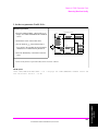
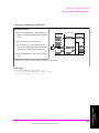
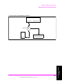
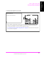
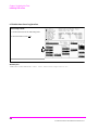
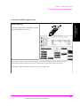
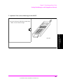
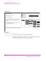
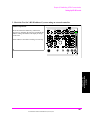
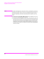
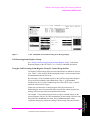
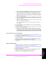
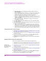
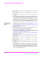
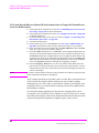
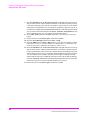
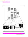
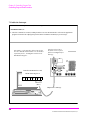
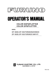
1. Connect the Test Set’s generator to the Test Set’s analyzer.
Manual Operation:
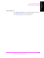
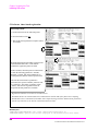
1. Connect cable(s) as shown.
CDMA CALL CONTROL
CALL
FUNCTIONS
END
CALL
ANS
INSTRUMENT STATE
MSG
PRINTER
I/O CONFIG
CONFIG
ADRS
SAVE
HOLD
HELP
PRINT
PREV
TESTS
LOCAL
RECALL
MEAS
RESET
PRESET
MEMOR
Y CARD
USER
CDMA SCRNS
k1’
CELL
DATA
DATA FUNCTIONS
RANGE
REF SET
METER
AVG
INCR
SET
INCR X10
k1
CALL
CTRL
RX
TEST
INCR
: 10
k2’
SPECTRUM
MSRPT
LO LIMIT
k2
GEN
CTRL
TX
TEST
k3
ANALOG SCRNS
ENCODER
DECODER
k4
RF
ANL
RX
TEST
AF
ANL
TX
TEST
RELEASE
CURSOR
CONTROL
SPEC ANL
SCOPE
RF
GEN
DUPLEX
SHIFT
MIC/ACC
9
ENTER
4
5
6
GHz
dBm
1
2
3
MHz
V
PUSH TO
SELECT
%
s
ACP
k5
8
dB
k3’
ASSIGN
7
HI LIMIT
+ _
kHz
mV
YES
NO
Ω
ms
ON/OFF
ppm
W
%
dBµV
Hz
µV
0
CANCEL
VOLUME
SQUELCH
AUDIO OUT
AUDIO IN
HI
POWER
LO
!
!
MAX PWR
MAX PWR
200 mW
6W
!
DO NOT APPLY
RF WHEN OFF
RF IN/OUT
ANTENNA IN
DUPLEX OUT
!
CDMA CALL
CALL
ANS
MAX
!
12 v Pk
FUNCTIO
END
MAX
42 v Pk
INSTRUMENT
MSG
PRINT
I/O
CONFI
ADRS
SAVE
HELP
PRINT
PREV
TESTS
LOCA
RECA
HOLD
MEAS
PRESE
MEM
USE
k1’
DATA
CDMA
CELL
CALL
RANG
RX
k2’
k2
k3’
k3
SPECTR
GEN
MSRP
TX
ASSIG
ENCO
RF
k1
REF
INCR
METE
INCR
LO
HI
CURSO
k4
RELE
DA
AVG
INCR
PUSH
ANALOG
DECO
RX
k5
AF
ACP
TX
SHIFT
SPEC
RF
SCOP
DUPL
MIC/
CANC
VOLU
SQUEL
7
4
1
0
8
5
2
YES
ON/
NO
ppm
+_
AUDIO
POWE
Ω
%
HI
dB
GHz
%
MHz
s
kHz
ms
Hz
AUDIO
L
!
!
MAX
MAX PWR
!
9
6
3
ENTE
DO NOT
DUPLEX
RF IN/
ANTENN
!
MAX
! MAX
8 32 36B
H
PC S IN TER FA CE
TEST SET
1.8-2.0 GHz UUT
POWER
FROM DUPLEX OUT
HP 83236 PCS INTERFACE
OFF
TO ANT IN
RF IN/OUT
RF OUT only
ON
30
N:\mkt\MANUALS\HP8924C\APPMOD\BOOK\chapters\amcal.fb
Chapter 1, Calibrating the Test Set
Calibrating Channel Power Measurements
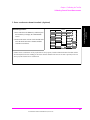
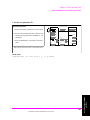
2. Enter an alternate channel standard. (Optional)
Chapter 1
Calibrating The Test Set
Manual Operation:
CONFIGURE
1. Press and release the SHIFT key and then press
the TESTS key to display the CONFIGURE
screen.
2. Position the cursor in front of Alt Chn Std field.
Press the knob and select a channel standard
from the list of choices.
RF In/Out
- X .X
dB
Duplex Out
- X .X
Antenna In
- X .X
Alt Chn Std
US PCS
Channel Power Calibration will be performed over the frequency bands included in the RF Chan Std and the
Alt Chn Std field selections. Adding an alternate channel standard will increase the time required for the Test
Set to perform Channel Power Calibration.
31
N:\mkt\MANUALS\HP8924C\APPMOD\BOOK\chapters\amcal.fb
Chapter 1, Calibrating the Test Set
Calibrating Channel Power Measurements
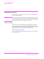
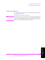
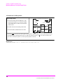
3. Select the Channel Power measurement.
Manual Operation:
1. Position the cursor next to the field that displays
Avg Power or Chan Power. This field is found
on the CDMA CALL CONTROL, CDMA
CELLULAR MOBILE TRANSMITTER
TEST, and CDMA TRANSMITTER POWER
RANGE TEST screens.
CDMA CELLULAR MOBILE TRANSMITTER TEST
Chan Power
2. Make sure Chan Power is selected:
a. Press the knob to display the Choices menu.
b. Select Chan Power from the list of choices.
HP-IB Syntax
"CDMA:TX:POW:MEAS ’Chan Power’" selects Channel Power measurements.
32
N:\mkt\MANUALS\HP8924C\APPMOD\BOOK\chapters\amcal.fb
Chapter 1, Calibrating the Test Set
Calibrating Channel Power Measurements
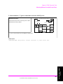
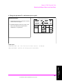
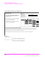
4. Calibrate the Channel Power measurement.
Manual Operation:
CDMA CELLULAR MOBILE TRANSIMITER TEST
Chapter 1
Calibrating The Test Set
1. Position the cursor next to the Power Meas
field.
Chan Power
2. Press the knob.
The Test Set will display "Zeroing Average
Power...", then "Calibrating Channel Power...."
until calibration is complete.
Power Meas
Calibrate
Calibration may take a minute or longer, depending on the RF Channel Std and Alt Chn Std field settings. If
you are performing calibration using the HP-IB command below, be aware that the Test Set will accept
(handshake) HP-IB commands during the calibration routine, but none of these "buffered" HP-IB command
functions will be executed until channel power calibration is complete.
HP-IB Help
If your controlling application has anI/O timeout enabled, and a query such as
"STAT:OPER:CAL:EVEN?" is sent after the channel power calibration has
started, make sure that sufficient time is given for the Test Set to complete
calibration and provide a query response in its output queue. Or, disable the
timeout during channel power calibration.
Bit 0 in the Calibrating Status Event Register is Digital Power Zeroing (Power
Meas "Zero" field). Bit 1 is Channel Power Calibration (Power Meas "Calibrate"
field). With the Transition Filter Register in its default state, the Test Set will
respond to the "STAT:OPER:CAL:EVEN?" query command with a decimal 3 .
HP-IB Syntax
"MEAS:CDM:CHAN:CAL" !calibrates Channel Power measurements.
"STAT:OPER:CAL:EVEN?" !queries the Calibrating Status Event Register"
Procedure Overview
1. "Connect the Test Set’s generator to the Test Set’s analyzer." on page 30.
RF IN/OUT and DUPLEX OUT connectors.
33
N:\mkt\MANUALS\HP8924C\APPMOD\BOOK\chapters\amcal.fb
Chapter 1, Calibrating the Test Set
Calibrating Channel Power Measurements
2. "Enter an alternate channel standard. (Optional)" on page 31
Screen: CONFIGURE
Enter choice in: Alt Chn Std
3. "Select the Channel Power measurement." on page 32.
Screen: CDMA CELLULAR MOBILE TRANSMITTER TEST
Enter choice in: Chan Power
4. "Calibrate the Channel Power measurement." on page 33.
Screen: CDMA CELLULAR MOBILE TRANSMITTER TEST
Calibrate select: Power Meas
34
N:\mkt\MANUALS\HP8924C\APPMOD\BOOK\chapters\amcal.fb
Chapter 1, Calibrating the Test Set
Calibrating RF Generator Levels
Calibrating RF Generator Levels
Approximate time: 15 seconds
RF generator levels should be calibrated whenever any of the following events
occur:
•
•
•
•
After a 30-minute warm-up period
After firmware is upgraded
If the RF connections to the PCS Interface are adjusted
If the ambient temperature drifts more than 5 °C after a 30-minute warm-up period
The PCS Interface’s internal compensation factors are used to compute the
generator path attenuator values and the required signal level from the Test Set’s
DUPLEX OUT port. The RF IN/OUT path is automatically de-coupled within the
PCS Interface during this procedure, so any RF link to a mobile station will be lost
This includes dropped calls and loss of CDMA or analog service from the Test
Set.
1. Select the RF Gen Lvl field.
Manual Operation:
CONFIGURE
1. Press and release the SHIFT key and then press
the TESTS key to display the CONFIGURE
screen.
2. Position the cursor at the RF Gen Lvl field.
3. Start calibration by pressing the knob.
RF Gen Lvl
Calibrate
HP-IB Syntax
"CONF:RFSource:CALibrate" ! calibrates RF Gen levels
35
N:\mkt\MANUALS\HP8924C\APPMOD\BOOK\chapters\amcal.fb
Chapter 1
Calibrating The Test Set
This procedure applies only to Test Sets configured with an HP 83236B PCS
Interface.
Chapter 1, Calibrating the Test Set
Zeroing Average Power Measurements
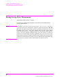
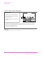
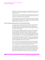
Zeroing Average Power Measurements
Approximate length of time: 2 seconds
Average Power measurements should be zeroed before each measurement or
series of measurements.
NOTE:
A misleading Average Power measurement may appear when low (or no) signal power
is applied to the RF Input! When the RF generator’s output port selection is RF IN/
OUT, some of the signal energy from the Test Set’s generator is detected by the Test Set’s
broadband average power meter. This condition does not affect typical CDMA
measurements for two reasons: 1) During Average Power measurements CDMA generator
levels are too low to introduce significant energy to the power detector. 2) When the
generator level is high enough to introduce significant energy to the power detector, the
mobile station’s signal power should be within the range of Channel Power measurements.
Channel power measurements are frequency-selective, and do not detect significant energy
from the Test Set’s generator, which is tuned 45 MHz away from the analyzer.
36
N:\mkt\MANUALS\HP8924C\APPMOD\BOOK\chapters\amcal.fb
Chapter 1, Calibrating the Test Set
Zeroing Average Power Measurements
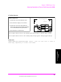
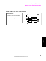
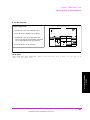
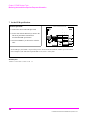
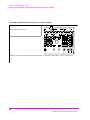
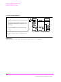
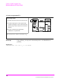
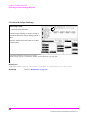
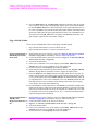
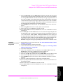
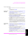
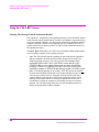
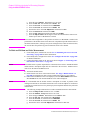
1. Remove power from the RF IN/OUT connector.
FUNCTIONS
END
CALL
ANS
Chapter 1
Calibrating The Test Set
CDMA CALL CONTROL
CALL
INSTRUMENT STATE
MSG
PRINTER
I/O CONFIG
CONFIG
ADRS
SAVE
HOLD
HELP
PRINT
PREV
TESTS
LOCAL
RECALL
MEAS
RESET
PRESET
MEMOR
Y CARD
USER
CDMA SCRNS
k1’
CELL
DATA
DATA FUNCTIONS
RANGE
REF SET
METER
AVG
INCR
SET
INCR X10
k1
CALL
CTRL
RX
TEST
INCR
: 10
k2’
SPECTRUM
MSRPT
LO LIMIT
k2
GEN
CTRL
TX
TEST
CURSOR
CONTROL
k3
ANALOG SCRNS
ENCODER
DECODER
k4
RF
ANL
RX
TEST
AF
ANL
TX
TEST
RELEASE
SPEC ANL
RF
GEN
SHIFT
9
ENTER
4
5
6
GHz
dBm
1
2
3
MHz
V
PUSH TO
SELECT
%
s
ACP
k5
8
dB
k3’
ASSIGN
7
HI LIMIT
+ _
kHz
mV
YES
NO
Ω
ms
ON/OFF
ppm
W
%
dBµV
Hz
µV
0
SCOPE
DUPLEX
CANCEL
MIC/ACC
VOLUME
SQUELCH
AUDIO OUT
AUDIO IN
HI
POWER
LO
!
!
MAX PWR
MAX PWR
200 mW
6W
!
DO NOT APPLY
RF WHEN OFF
RF IN/OUT
ANTENNA IN
DUPLEX OUT
!
CDMA CALL
CALL
ANS
MAX
!
12 v Pk
FUNCTIO
END
MAX
42 v Pk
INSTRUMENT
MSG
PRINT
I/O
CONFI
ADRS
SAVE
HELP
PRINT
PREV
TESTS
LOCA
RECA
HOLD
MEAS
PRESE
MEM
USE
CELL
CALL
RANG
RX
k2’
SPECTR
GEN
MSRP
TX
k2
k3’
k3
ASSIG
k4
RELE
DATA
CDMA
k1’
k1
REF
INCR
METE
INCR
LO
DA
AVG
INCR
HI
CURSO
PUSH
ANALOG
ENCO
RF
DECO
RX
k5
AF
ACP
TX
SHIFT
SPEC
RF
SCOP
DUPL
MIC/
CANC
VOLU
SQUEL
7
4
1
0
8
5
2
YES
ON/
NO
ppm
+_
AUDIO
POWE
Ω
%
HI
dB
GHz
%
MHz
s
kHz
ms
Hz
AUDIO
L
!
!
MAX
MAX PWR
!
9
6
3
ENTE
DO NOT
DUPLEX
RF IN/
ANTENN
!
MAX
! MAX
832 36 B
H
P CS IN TE RF ACE
TEST SET
1.8-2.0 GHz UUT
POWER
FROM DUPLEX OUT
OFF
TO ANT IN
RF IN/OUT
RF OUT only
ON
HP 83236 PCS INTERFACE
37
N:\mkt\MANUALS\HP8924C\APPMOD\BOOK\chapters\amcal.fb
Chapter 1, Calibrating the Test Set
Zeroing Average Power Measurements
2. Lower the Test Set’s output power if necessary.
Manual Operation:
1. Press the PRESET key, which will set RF
Power to a level that will not degrade Average
Power zeroing, or turn off all sources as
follows:
Sector A Power
CDMA GENERATOR CONTROL
Sector B Power
AWGN
Off
Off
Off
2. Press the GEN CTRL key to display the
CDMA GENERATOR CONTROL screen.
3. Turn off Sector A Power, Sector B Power, and
AWGN (by pressing the ON/OFF key on the
Test Set’s front panel).
Turning off power from the CDMA generators will prevent power from cross-coupling internally to the
RF IN/OUT path during Average Power measurement zeroing.
Presetting the test Set (*RST HP-IB command) will turn off Sector B and AWGN, and will lower Sector A
Power to a level that will not affect zeroing the Average Power measurement, making it unnecessary to turn
Sector A Power off.
HP-IB Syntax
"CDMA:CELL:ASEC:STAT OFF" !turns off Sector A Power
"CDMA:CELL:BSEC:STAT OFF" !turns off Sector B Power
"CDMA:AWGN:STAT OFF" !turns off AWGN
38
N:\mkt\MANUALS\HP8924C\APPMOD\BOOK\chapters\amcal.fb
Chapter 1, Calibrating the Test Set
Zeroing Average Power Measurements
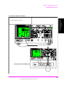
3. Select the Average Power measurement.
Manual Operation:
CDMA CELLULAR MOBILE TRANSMITTER TEST
Chapter 1
Calibrating The Test Set
1. Press the CDMA SCRNS - TX TEST key to
display the CDMA CELLULAR MOBILE
TRANSMITTER TEST screen.
Avg Power
2. Position the cursor next to the field as shown.
3. Press the knob to select the Choices menu.
4. Select Avg Power from the list.
HP-IB Syntax
"CDMA:TX:POW:MEAS ’Avg Power’" selects Average Power measurements.
39
N:\mkt\MANUALS\HP8924C\APPMOD\BOOK\chapters\amcal.fb
Chapter 1, Calibrating the Test Set
Zeroing Average Power Measurements
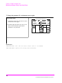
4. Zero the Average Power measurement.
Manual Operation:
CDMA CELLULAR MOBILE TRANSMITTER TEST
1. Press the CDMA SCRNS - TX TEST key to
display the CDMA CELLULAR MOBILE
TRANSMITTER TEST screen.
Avg Power
2. Position the cursor next to the Zero field.
3. Press the knob.
Zeroing Average Power takes approximately
two seconds.
Power Meas
Zero
If RF power was not lowered as shown in step 2, the Test Set will display "Zero degraded. Reduce generator
level for best results" .
HP-IB Syntax
"MEAS:CDM:AVGP:ZERO" ! zeroes the average power meter.
Procedure Overview
1. "Remove power from the RF IN/OUT connector." on page 37.
RF IN/OUT connector.
2. "Lower the Test Set’s output power if necessary." on page 38.
Screen: CDMA GENERATOR CONTROL
Turn off: Sector A Power, Sector B Power, AWGN
3. "Select the Average Power measurement." on page 39.
Screen: CDMA CELLULAR MOBILE TRANSMITTER TEST
Enter choice in: Avg Power
4. "Zero the Average Power measurement." on page 40.
Screen: CDMA CELLULAR MOBILE TRANSMITTER TEST
Observe: Power Meas
40
N:\mkt\MANUALS\HP8924C\APPMOD\BOOK\chapters\amcal.fb
Chapter 1, Calibrating the Test Set
Correcting for RF Path Loss
Correcting for RF Path Loss
Chapter 1
Calibrating The Test Set
Approximate time: N/A (this procedure is simply a field entry).
The settings you make in the following procedure must be re-entered after a
power-cycle, instrument preset, or HP-IB reset ("*RST).
It is highly recommended that RF path loss is corrected for in the following
manner.
NOTE:
The Test Set’s attenuator auto-ranging algorithm, used for adjusting gain in the RF analyzer
path, estimates the expected power level from the phone using the open loop power control
formula. External path loss, entered in the procedure below, is used by the auto-ranging
algorithm to ensure the analyzer is not overdriven or underdriven.
41
N:\mkt\MANUALS\HP8924C\APPMOD\BOOK\chapters\amcal.fb
Chapter 1, Calibrating the Test Set
Correcting for RF Path Loss
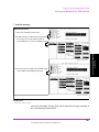
1. Enter the path loss from the Test Set to the MSUT.
If you do not know the path loss for your connecting hardware, see "Determining
RF Path Loss" on page 44
Manual Operation:
1. Press and release the SHIFT key and then press
the TESTS key to display the CONFIGURE
screen.
2. Position the cursor in front of the appropriate
field or fields below the RF Level Offset field
and enter a value for RF path loss.
CONFIGURE
RF In/Out
- X .X
dB
Duplex Out
- X .X
Antenna In
- X .X
Example: If the measured loss is 2 dB, and you are using the RF In/Out port, enter -2 dB in the RF In/Out
field. When the RF Level Offset is turned on, the displayed Average or Channel Power measurement will be
increased by 2 dB and the displayed Sector A, Sector B, AWGN, and RF Power outputs will be decreased by
2 dB. No actual level changes occur as a result of turning on RF Level Offset.
42
N:\mkt\MANUALS\HP8924C\APPMOD\BOOK\chapters\amcal.fb
Chapter 1, Calibrating the Test Set
Correcting for RF Path Loss
2. Turn on RF Level Offset.
Manual Operation:
CONFIGURE
Chapter 1
Calibrating The Test Set
1. Position the cursor at the RF Level Offset field.
RF Level
Offset
On/Off
RF In/Out
- X .X
2. Select "On" to correct for RF path loss.
dB
Duplex Out
- X .X
Antenna In
- X .X
43
N:\mkt\MANUALS\HP8924C\APPMOD\BOOK\chapters\amcal.fb
Chapter 1, Calibrating the Test Set
Determining RF Path Loss
Determining RF Path Loss
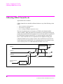
The following procedure describes how to use the Test Set’s signal generator and
analyzer to determine path loss.
NOTE:
The Test Set’s attenuator auto-ranging algorithm, used for adjusting gain in the RF analyzer
path, estimates the expected power level from the phone using the open loop power control
formula. External path loss, entered in the procedure below, is applied to the auto-ranging
algorithm to ensure the analyzer is not overdriven or underdriven.
Procedure Prerequisites
Provide a reference cable, cable and hardware in RF path to MSUT, and adapters
You must provide a reference cable and the cable adapters necessary to mate the
reference cable and the hardware that will be used in the path from the Test Set to
the MSUT. Choose a reference cable with as little loss as possible.
Zero the Average Power measurement
Refer to "Zeroing Average Power Measurements" on page 36 if necessary, and then
return to this procedure.
44
N:\mkt\MANUALS\HP8924C\APPMOD\BOOK\chapters\amcal.fb
Chapter 1, Calibrating the Test Set
Determining RF Path Loss
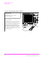
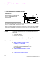
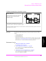
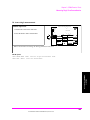
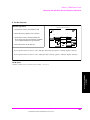
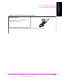
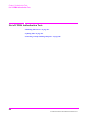
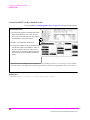
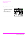
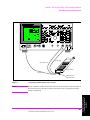
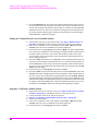
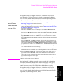
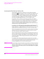
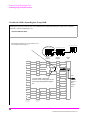
1. Connect a reference cable(s).
Manual Operation:
Chapter 1
Calibrating The Test Set
1. Connect cable(s) as shown.
CDMA CALL CONTROL
CALL
FUNCTIONS
END
CALL
ANS
INSTRUMENT STATE
MSG
PRINTER
I/O CONFIG
CONFIG
ADRS
SAVE
HOLD
HELP
PRINT
PREV
TESTS
LOCAL
RECALL
MEAS
RESET
PRESET
MEMOR
Y CARD
USER
k1’
CDMA SCRNS
CELL
DATA
DATA FUNCTIONS
RANGE
REF SET
METER
AVG
INCR
SET
INCR X10
k1
CALL
CTRL
RX
TEST
INCR
: 10
k2’
SPECTRUM
MSRPT
LO LIMIT
k2
GEN
CTRL
TX
TEST
CURSOR
CONTROL
k3
ANALOG SCRNS
ENCODER
DECODER
k4
RF
ANL
RX
TEST
AF
ANL
TX
TEST
RELEASE
k5
SHIFT
SCOPE
RF
GEN
DUPLEX
9
ENTER
4
5
6
GHz
dBm
1
2
3
MHz
V
+ _
kHz
mV
PUSH TO
SELECT
%
s
ACP
SPEC ANL
8
dB
k3’
ASSIGN
7
HI LIMIT
0
CANCEL
MIC/ACC
VOLUME
YES
NO
Ω
ms
ON/OFF
ppm
W
%
dBµV
Hz
µV
SQUELCH
AUDIO OUT
AUDIO IN
HI
POWER
LO
!
!
MAX PWR
MAX PWR
200 mW
6W
!
DO NOT APPLY
RF WHEN OFF
RF IN/OUT
DUPLEX OUT
ANTENNA IN
!
MAX
!
12 v Pk
MAX
42 v Pk
Low-loss reference cable
CDMA CALL
CALL
ANS
FUNCTIO
END
INSTRUMENT
MSG
PRINT
I/O
CONFI
ADRS
SAVE
HELP
PRINT
PREV
TESTS
LOCA
RECA
HOLD
MEAS
PRESE
MEM
USE
k1’
k1
k2’
k2
k3’
k3
ASSIG
k4
RELE
RANG
RX
SPECTR
GEN
MSRP
TX
POWE
REF
INCR
METE
INCR
LO
DA
AVG
INCR
HI
CURSO
PUSH
ANALOG
ENCO
RF
DECO
RX
k5
AF
ACP
TX
SHIFT
SPEC
RF
SCOP
DUPL
MIC/
CANC
VOLU
SQUEL
7
8
9
4
1
0
5
2
6
3
YES
ON/
NO
ppm
+_
AUDIO
Ω
%
HI
ENTE
dB
GHz
%
MHz
s
kHz
ms
Hz
AUDIO
L
!
!
MAX
MAX PWR
!
DATA
CDMA
CELL
CALL
DO NOT
RF IN/
DUPLEX
ANTENN
!
MAX
! MAX
8 323 6B
H
PC S INT ER FA CE
TEST SET
1.8-2.0 GHz UUT
POWER
HP 83236 PCS INTERFACE
FROM DUPLEX OUT
OFF
TO ANT IN
RF IN/OUT
RF OUT only
ON
45
N:\mkt\MANUALS\HP8924C\APPMOD\BOOK\chapters\amcal.fb
Chapter 1, Calibrating the Test Set
Determining RF Path Loss
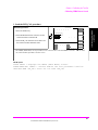
2. Configure the Test Set for RF loopback.
Manual Operation:
1. Press and release the SHIFT key and then press
the TESTS key to display the CONFIGURE
screen.
NO PCS INTERFACE
CONFIGURE
2. Position the cursor at the Output Port field.
3. Select Dupl (if no PCS Interface is configured)
or only (if a PCS Interface is configured) by
pressing the knob to toggle the underlined
selection.
Output Port
RF Out/Dupl
Input Port
RF In/Ant
Skip steps 4 and 5 if a PCS Interface is configured
4. Position the cursor at the Input Port field.
PCS INTERFACE CONFIGURED
CONFIGURE
5. Select RF In if it isn’t already selected.
Output Port
RF Out/Only
46
N:\mkt\MANUALS\HP8924C\APPMOD\BOOK\chapters\amcal.fb
Chapter 1, Calibrating the Test Set
Determining RF Path Loss
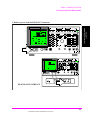
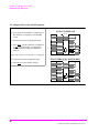
3. Determine a reference for the path loss measurement.
Manual Operation:
2. Position the cursor at the Sector A Power field.
3. Set the value to -11.0 dBm/BW with the DATA
keys.
Chapter 1
Calibrating The Test Set
1. Press the CDMA SCRNS - TX TEST key to
display the CDMA CELLULAR MOBILE
TRANSMITTER TEST screen.
CDMA CELLULAR MOBILE TRANSMITTER TEST
Avg Power
dBm
Sector A
Power
-11.0
dB/BW
4. Position the cursor at the units-of-measure field
and press the knob.
5. Press and release the SHIFT key, then press the
INCR ÷ 10 key to set a 0 dBm reference.
47
N:\mkt\MANUALS\HP8924C\APPMOD\BOOK\chapters\amcal.fb
Chapter 1, Calibrating the Test Set
Determining RF Path Loss
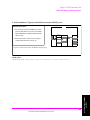
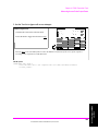
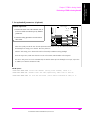
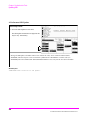
4. Connect the cable and hardware being measured for path loss.
CDMA CALL CONTROL
CALL
FUNCTIONS
END
CALL
ANS
INSTRUMENT STATE
MSG
PRINTER
I/O CONFIG
CONFIG
ADRS
SAVE
HOLD
HELP
PRINT
PREV
TESTS
LOCAL
RECALL
MEAS
RESET
PRESET
MEMOR
Y CARD
USER
k1’
CDMA SCRNS
CELL
DATA
DATA FUNCTIONS
RANGE
REF SET
METER
AVG
INCR
SET
INCR X10
k1
CALL
CTRL
RX
TEST
INCR
: 10
k2’
SPECTRUM
MSRPT
LO LIMIT
k2
GEN
CTRL
TX
TEST
CURSOR
CONTROL
k3
ANALOG SCRNS
ENCODER
DECODER
k4
RF
ANL
RX
TEST
AF
ANL
TX
TEST
RELEASE
k5
SHIFT
9
ENTER
4
5
6
GHz
dBm
1
2
3
MHz
V
PUSH TO
SELECT
%
s
ACP
SPEC ANL
RF
GEN
8
dB
k3’
ASSIGN
7
HI LIMIT
+ _
kHz
mV
YES
NO
Ω
ms
ON/OFF
ppm
W
%
dBµV
Hz
µV
0
SCOPE
DUPLEX
CANCEL
MIC/ACC
VOLUME
SQUELCH
AUDIO OUT
AUDIO IN
HI
POWER
LO
!
!
MAX PWR
MAX PWR
200 mW
6W
!
DO NOT APPLY
RF WHEN OFF
RF IN/OUT
DUPLEX OUT
ANTENNA IN
!
MAX
!
12 v Pk
MAX
42 v Pk
Low-loss reference cable
CDMA CALL
CALL
ANS
FUNCTIO
END
INSTRUMENT
MSG
PRINT
I/O
CONFI
ADRS
SAVE
HELP
PRINT
PREV
TESTS
LOCA
RECA
HOLD
MEAS
PRESE
MEM
USE
k1’
k1
k2’
k2
k3’
k3
DATA
CDMA
CELL
CALL
RANG
RX
SPECTR
GEN
MSRP
TX
REF
INCR
METE
INCR
LO
k4
RELE
AVG
INCR
HI
CURSO
ASSIG
DA
PUSH
ANALOG
ENCO
RF
DECO
RX
k5
AF
ACP
TX
SHIFT
SPEC
RF
SCOP
DUPL
MIC/
CANC
VOLU
SQUEL
7
8
9
4
1
0
5
2
6
3
YES
ON/
NO
ppm
+_
AUDIO
POWE
Cable being measured
HI
dB
GHz
%
MHz
s
kHz
ms
Hz
AUDIO
L
!
!
MAX
MAX PWR
!
Ω
%
ENTE
DO NOT
RF IN/
DUPLEX
ANTENN
!
MAX
! MAX
83 23 6B
H
PCS INTERFAC E
TEST SET
1.8-2.0 GHz UUT
POWER
FROM DUPLEX OUT
OFF
TO ANT IN
RF IN/OUT
RF OUT only
ON
HP 83236 PCS INTERFACE
48
N:\mkt\MANUALS\HP8924C\APPMOD\BOOK\chapters\amcal.fb
Chapter 1, Calibrating the Test Set
Determining RF Path Loss
5. Determine the path loss.
Observe the average power measurement reading.
Chapter 1
Calibrating The Test Set
This is the measured RF path loss that should be entered in the Test Set’s
Configure screen. See "Correcting for RF Path Loss" on page 41
CDMA CELLULAR MOBILE TRANSMITTER TEST
Avg Power
dBm
-3.00
Ref
Sector A
Power
-11.0
dB/BW
49
N:\mkt\MANUALS\HP8924C\APPMOD\BOOK\chapters\amcal.fb
Chapter 1, Calibrating the Test Set
Determining RF Path Loss
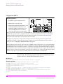
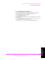
6. Re-configure the Test Set.
Manual Operation:
CDMA CALL CONTROL
1. Press the PRESET key
CALL
ANS
END
CALL
FUNCTIONS
INSTRUMENT STATE
MSG
PRINTER
I/O CONFIG
CONFIG
ADRS
SAVE
HOLD
HELP
PRINT
PREV
TESTS
LOCAL
RECALL
MEAS
RESET
PRESET
MEMOR
Y CARD
USER
k1’
CDMA SCRNS
CELL
RANGE
REF SET
METER
AVG
INCR
SET
INCR X10
k1
CALL
CTRL
RX
TEST
INCR
: 10
k2’
SPECTRUM
MSRPT
LO LIMIT
k2
GEN
CTRL
TX
TEST
k3
ANALOG SCRNS
ENCODER
DECODER
k4
RF
ANL
RX
TEST
RELEASE
k5
SHIFT
SCOPE
RF
GEN
DUPLEX
MIC/ACC
9
ENTER
4
5
6
GHz
dBm
1
2
3
MHz
V
+ _
kHz
mV
PUSH TO
SELECT
%
s
0
TX
TEST
SPEC ANL
8
dB
CURSOR
CONTROL
ACP
AF
ANL
7
HI LIMIT
k3’
ASSIGN
DATA
DATA FUNCTIONS
CANCEL
VOLUME
SQUELCH
YES
NO
Ω
ms
ON/OFF
ppm
W
%
dBµV
Hz
µV
AUDIO OUT
AUDIO IN
HI
!
MAX
12 v Pk
LO
!
MAX
42 v Pk
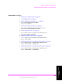
Procedure Overview
1. "Connect a reference cable(s)." on page 45.
2. "Configure the Test Set for RF loopback." on page 46.
Screen: CONFIGURE
3. "Determine a reference for the path loss measurement." on page 47.
Screen: TRANSMITTER TEST
4. "Connect the cable and hardware being measured for path loss." on page 48.
5. "Determine the path loss." on page 49.
Screen: TRANSMITTER TEST
6. "Re-configure the Test Set." on page 50.
50
N:\mkt\MANUALS\HP8924C\APPMOD\BOOK\chapters\amcal.fb
N:\mkt\MANUALS\HP8924C\APPMOD\BOOK\chapters\amcall.fb
Setting Up a Call
2
51
Chapter 2
Setting Up a Call
Chapter 2, Setting Up a Call
Setting up a Call
Setting up a Call
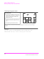
1. Preset the Test Set.
Manual Operation:
1. Turn on power to the Test Set and PCS
Interface, if installed.
2. Wait for the Test Set to complete its power-up
routine.
3. Press the PRESET key (in case the Test Set
does not power up to factory default settings)
CDMA CALL CONTROL
Call Status
Transmitting
Page Sent
Access Probe
Connected
Softer Handoff
Hard Handoff
RF Channel
384
Register
Softer
Handoff
Begin/End
Answer Mode
Auto/Manual
Call Limit
None/Page
MS FER Report
%
Avg Power
dBm
---MS FER
Report
Interval
5 frames
by # frames
On/Off
by # frames
On/Off
5
Traffic
Data Mode
Svc Opt 1
Data Type
Echo
Echo Delay
Short
Avg Power
Power Zero
MS ID
Phone Num
5099214001
MS Database
ESN
1234
Sector A
Power
-73.0
dBm/BW
To Screen
CDMA
CALL CNTL
Analog
RX TEST
Cnfig
PRNT CNFG
Pressing the PRESET key will configure the Test Set using factory default settings, and display the CDMA
CALL CONTROL screen.
HP-IB Syntax:
"*RST" !configures the Test Set using factory default settings, and displays the CDMA
CALL CONTROL screen.
52
N:\mkt\MANUALS\HP8924C\APPMOD\BOOK\chapters\amcall.fb
Chapter 2, Setting Up a Call
Setting up a Call
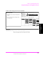
2. Turn on PCS mode if necessary (Optional).
This step does not need to be performed if the Test Set was configured for PCS
mode when last powered down. This step is only applicable to Test Sets with the
HP 83236 PCS Interface and firmware later than A.05.00. The PCS Interface must
be installed according to instructions found in the HP 83236B PCS Interface
Operating Manual.
Manual Operation:
CONFIGURE
1. Press then release the SHIFT key then press the
TESTS key to display the CONFIGURE
screen.
RF Level
Offset
On/Off
RF In/Out
- 2.0
2. Position the cursor at the PCS Mode field.
3. Press the knob to underline “On”.
PCS Mode
On/Off
Chapter 2
Setting Up a Call
4. Cycle power to the Test Set to initialize
communication between the Test Set and PCS
Interface.
5. Preset the Test Set.
The PCS Interface extends the measurement capability of the HP 8924C to include the PCS frequency range.
The Test Set, when installed with firmware revision A.05.00 or higher, controls the PCS Interface via the rearpanel serial AUX CONTROL interface. A rocker switch on the PCS Interface rear panel labeled “HP-IB/Ser”
must be in the “Ser” position for serial control.
When switching between the cellular and PCS frequency bands it is not necessary to turn PCS Mode “Off”.
This is because the PCS Interface provides conversion bypass paths (bypassing frequency up-conversion on
the generator path and frequency down-conversion on the analyzer path) for operation in the cellular band.
HP-IB Syntax:
"CONF:PCSM ‘On’" !turns PCS mode on
53
N:\mkt\MANUALS\HP8924C\APPMOD\BOOK\chapters\amcall.fb
Chapter 2, Setting Up a Call
Setting up a Call
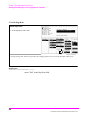
3. Correct for RF Path Loss.
Manual Operation:
CONFIGURE
1. Press then release the SHIFT key then press the
TESTS key to display the CONFIGURE
screen, if it is not already displayed.
RF Level
Offset
On/Off
RF In/Out
- 2.0
dB
2. Position the cursor at the RF In/Out field.*
3. Enter the RF path loss. For example, if the RF
path loss is 2 dB, enter -2 in the RF In/Out field.
PCS Mode
On/Off
4. Position the cursor at the RF Level Offset field.
5. Select On to apply the offset.
6. Press the PREV key to return to the CDMA
CALL CONTROL screen.
If you need a method for measuring path loss, refer to "Determining RF Path Loss" on page 44.
The Test Set corrects for path loss by changing displayed values. Example: If an RF path loss of -2 dB is
entered in the RF In/Out field, and RF Level Offset is turned on, input power measurements will be 2 dB
greater than the same measurement with RF Level Offset turned off.
Correcting for RF path loss allows the Test Set to achieve accurate gain settings in the RF analyzer path.
*If you are using an external duplexer, enter the path loss in the Duplex Out and Antenna In fields (displayed
when the PCS Mode field is set to “Off”).
HP-IB Syntax:
"CONF:OFL:RFIN -2;MODE ‘ON’" !enters an RF path loss of 2 dB for the path to the RF In/
Out connector, and turns the RF level offset On.
54
N:\mkt\MANUALS\HP8924C\APPMOD\BOOK\chapters\amcall.fb
Chapter 2, Setting Up a Call
Setting up a Call
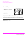
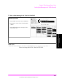
4. Enter the Protocol and RF Channel Standard of the mobile station under test (MSUT).
Manual Operation:
CDMA CALL CONTROL
1. Press the CALL CTRL key to display the
CONFIGURE screen.
2. Position the cursor at the Protocol field.
3. Press the knob to select the field.
4. Select the Protocol from the list of choices.
Call Status
Transmitting
Page Sent
Access Probe
Connected
Softer Handoff
Hard Handoff
RF Channel
384
Register
Softer
Handoff
Begin/End
Protocol
Auto/Manual
RF Chan Std
None/Page
MS FER Report
%
Avg Power
dBm
---MS FER
Report
Interval
5 frames
by # frames
On/Off
by # frames
On/Off
5
Traffic
Data Mode
Svc Opt 1
Data Type
Echo
Echo Delay
Short
Avg Power
Power Zero
MS ID
Phone Num
5099214001
MS Database
ESN
1234
Sector A
Power
-75.0
dBm/BW
To Screen
CDMA
CALL CNTL
Analog
RX TEST
Cnfig
PRNT CNFG
5. Position the cursor at the RF Chan Std field.
6. Press the knob to select the field.
Chapter 2
Setting Up a Call
6. Select an RF Channel Standard from the list of
choices.
The list of RF Chan Std choices includes only those supported by the hardware configuration. Some RF
channel standards require the HP 83236B with Option 007 (Wideband). Refer to the RF Chan Std field
description in the HP 8924C Reference Guide.
HP-IB Syntax:
"CDMA:CELL:PROT ‘IS-95A’”!selects the IS-95A protocol stack.
"CONF:RFCS ‘MS AMPS’” !selects the AMPS RF channel standard.
55
N:\mkt\MANUALS\HP8924C\APPMOD\BOOK\chapters\amcall.fb
Chapter 2, Setting Up a Call
Setting up a Call
5. Enter the MSUT’s primary CDMA channel.
Manual Operation:
1. Position the cursor at the RF Channel field.
2. Enter the MSUT’s Primary CDMA channel
using the DATA keys.
3. Press the ENTER key or press the knob to enter
the value.
CDMA CALL CONTROL
Call Status
Transmitting
Page Sent
Access Probe
Connected
Softer Handoff
Hard Handoff
RF Channel
384
Register
Softer
Handoff
Begin/End
Protocol
IS-95A
RF Chan Std
MS AMPS
MS FER Report
%
Avg Power
dBm
---MS FER
Report
Interval
5 frames
by # frames
On/Off
by # frames
On/Off
5
Traffic
Data Mode
Svc Opt 1
Data Type
Echo
Echo Delay
Short
Avg Power
Power Zero
MS ID
Phone Num
5099214001
MS Database
ESN
1234
Sector A
Power
-75.0
dBm/BW
To Screen
CDMA
CALL CNTL
Analog
RX TEST
Cnfig
PRNT CNFG
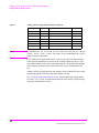
The MSUT’s primary CDMA channel depends on its preferred serving system (System A or System B).
Listed below are the primary CDMA channels specified in EIA/TIA IS-95 for System A and System B.
System A Primary CDMA Channel: 283.
System B Primary CDMA Channel: 384.
HP-IB Syntax:
“DISP CCNT;CDMA:RFCH 384” !selects channel 384.
56
N:\mkt\MANUALS\HP8924C\APPMOD\BOOK\chapters\amcall.fb
Chapter 2, Setting Up a Call
Setting up a Call
6. Adjust Sector A Power. (Optional)
CDMA CALL CONTROL
Manual Operation:
1. Position the cursor at the Sector A Power field.
2. Set the desired value using the DATA keys.
3. Press the ENTER key or press the knob to enter
the value.
Call Status
Transmitting
Page Sent
Access Probe
Connected
Softer Handoff
Hard Handoff
RF Channel
384
Register
Softer
Handoff
Begin/End
Answer Mode
Auto/Manual
Call Limit
None/Page
MS FER Report
%
Avg Power
dBm
---MS FER
Report
Interval
5 frames
by # frames
On/Off
by # frames
On/Off
5
Traffic
Data Mode
Svc Opt 1
Data Type
Echo
Echo Delay
Short
Avg Power
Power Zero
MS ID
Phone Num
5099214001
MS Database
ESN
1234
Sector A
Power
-75.0
dBm/BW
To Screen
CDMA
CALL CNTL
Analog
RX TEST
Cnfig
PRNT CNFG
Sector A Power levels to the MSUT should be within the range of -25 dBm/BW to -105 dBm/BW. If the level of
interference from other cellular signals is negligible, the preset value of -75 dBm/BW will be adequate for
setting up a call.
When entering Sector A Power values via the HP-IB, the default unit-of-measure
is “dBm per 1.23 MHz bandwidth”, expressed as dBm/BW on the display.
HP-IB Syntax:
"DISP CCNT;CDMA:CELL:ASEC -75" !sets Sector A Power to -75 dBm/1.23 MHz bandwidth.
57
N:\mkt\MANUALS\HP8924C\APPMOD\BOOK\chapters\amcall.fb
Chapter 2
Setting Up a Call
HP-IB Help:
Chapter 2, Setting Up a Call
Setting up a Call
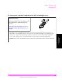
7. Connect the mobile-station-under-test (MSUT).
Manual Operation:
CDMA CALL CONTROL
Connect the MSUT to the Test Set’s
RF IN/OUT connector.
CALL
USER
Make sure all connections to the MSUT, including
dc power, are made.
Some MSUT’s do not have an RF connection. The
MSUT manufacturer will usually make a fixture,
such as a car adapter, that will provide an RF cable
connection to the Test Set. The MSUT is then
snapped into the fixture and an RF connection is
made through an electromagnetic coupler near the
MSUT antenna. When setting up a call with these
type of MSUT’s, the MSUT may need to be isolated
from interfering signals.
ANS
END
CALL
CDMA SCRNS
k1’
CELL
k1
CALL
CTRL
RX
TEST
k2’
SPECTRUM
MSRPT
k2
GEN
CTRL
TX
TEST
RANGE
k3’
k3
ANALOG SCRNS
ASSIGN
ENCODER
DECODER
k4
RF
ANL
RX
TEST
ACP
RELEASE
k5
SHIFT
AF
ANL
TX
TEST
SPEC ANL
SCOPE
RF
GEN
DUPLEX
MIC/ACC
POWER
!
!
MAX PWR
MAX PWR
200 mW
6W
!
DO NOT APPLY
RF WHEN OFF
RF IN/OUT
DUPLEX OUT
ANTENNA IN
58
N:\mkt\MANUALS\HP8924C\APPMOD\BOOK\chapters\amcall.fb
Chapter 2, Setting Up a Call
Setting up a Call
8. Turn on power to the MSUT and wait for the MSUT to find digital service.
Manual Operation:
Wait until the MSUT has found digital service
(this should take no longer than about 30
seconds).
If the MSUT does not find service, refer to
"Checklist 1. MSUT did not find service" on
page 68.
Most MSUT’s have a NO SERVICE annunciator that will go out when the mobile station has found service.
Other MSUT’s use an LED that indicates when service has been found. If the MSUT is programmed to prefer
analog service, and a strong signal from an analog base station is present, the MSUT may not find digital
service. If this condition exists, re-program the phone or isolate it from the competing analog signal.
Chapter 2
Setting Up a Call
Caution: Do not exceed 6 W continuous power into the Test Set’s RF IN/OUT connector with any transmitter.
59
N:\mkt\MANUALS\HP8924C\APPMOD\BOOK\chapters\amcall.fb
Chapter 2, Setting Up a Call
Setting up a Call
9. Select the desired Service Option.
Manual Operation:
CDMA CALL CONTROL
Call Status
Transmitting
Page Sent
Access Probe
Connected
Softer Handoff
Hard Handoff
1. Position the cursor at the Traffic Data Mode
field.
2. Press the knob to select the field.
3. Select a Service Option.
RF Channel
384
Register
Softer
Handoff
Begin/End
Protocol
IS-95A
RF Chan Std
MS AMPS
MS FER Report
%
Avg Power
dBm
---MS FER
Report
Interval
5 frames
by # frames
On/Off
by # frames
On/Off
5
Traffic
Data Mode
Svc Opt 1
Data Type
Echo
Echo Delay
Short
Avg Power
Power Zero
MS ID
Phone Num
5099214001
MS Database
ESN
1234
Sector A
Power
-75.0
dBm/BW
To Screen
CDMA
CALL CNTL
Analog
RX TEST
Cnfig
PRNT CNFG
Service Option 1 and 9 select voice loopback (normal traffic) mode. When a Service Option 1 or 9 call is
connected, the Test Set will echo voice information back to the MSUT with a settable delay.
Service Option 2 and 32768 select data loopback mode specified by IS-98 for MSUT receiver testing.
HP-IB Syntax:
"DISP CCNT;CDMA:CALL:TRAF:DATA:MODE ’SVC OPT 2’"
!selects service option 2 (data loopback mode)
60
N:\mkt\MANUALS\HP8924C\APPMOD\BOOK\chapters\amcall.fb
Chapter 2, Setting Up a Call
Setting up a Call
10. Register the MSUT (MSUT must be “roaming” and not in the process of power-up
registration).
If you are going to make a call from the MSUT, or if you allow the MSUT to
perform a power-up registration, you can skip this step and continue with "MSUTOriginated Call" on page 64.
IMPORTANT
If your MSUT is programmed to operate “Home Only,” or if the Pwr Up
Reg field on the CDMA CELL SITE CONFIGURATION screen is “On”
and the mobile station has not registered yet, this registration procedure
will likely fail (in this case the error message “Time-out occurred while
attempting to register mobile...” will be displayed). If you know your
MSUT’s preferred system is “Home Only,” either re-program the MSUT
to allow roaming, or skip Step 10 and continue with "MSUT-Originated
Call" on page 64 or re-program the MSUT to allow roaming.
Manual Operation:
CDMA CALL CONTROL
2. Push the knob to select the Register field. The
Registering annunciator will light.
RF Channel
384
Register
Softer
Handoff
Begin/End
Protocol
IS-95A
RF Chan Std
MS AMPS
MS FER Report
%
Avg Power
dBm
Chapter 2
Setting Up a Call
1. Position the cursor at the Register field.
Optional: Select *Clr All* in the MS Database
list of choices to remove any data from
previous registrations.
Call Status
Transmitting
Registering
Access Probe
Connected
Softer Handoff
Hard Handoff
---MS FER
Report
Interval
5 frames
by # frames
On/Off
by # frames
On/Off
5
Traffic
Data Mode
Svc Opt 1
Data Type
Echo
Echo Delay
Short
Avg Power
Power Zero
MS ID
Phone Num
5099214001
MS Database
ESN
1234
Sector A
Power
-75.0
dBm/BW
To Screen
CDMA
CALL CNTL
Analog
RX TEST
Cnfig
PRNT CNFG
3. Watch for the Registering annunciator to go
out. If the registration attempt times out, refer
to "Checklist 2. Registration failed" on page
70.
Registration provides the Test Set with the MSUT’s identification, thereby enabling the Test Set to correctly
address pages. (An alternative method for providing the Test Set with the MSUT’s identification is to enter
Phone Number, MIN, or IMSI directly into the MS ID field on the CDMA Call Control screen. This
alternative method could result in significant time savings in a production test environment but the numbers
you enter must precisely match the internal NAM (Numeric Assignment Module) settings in the MSUT and the
MSUT must be non-slotted).
When the Register field is selected, values entered in the CDMA Cell Site Configuration screen’s Rgstr SID
and Rgstr NID fields are sent to the MSUT in a message called the System Parameters message. This SID/
NID pair causes the MSUT to perform a “zone-based” registration. The Rgstr SID and Rgstr NID fields are
set by default to 12. These values do not need to be changed unless the MSUT is programmed to not recognize
them as valid, or the MSUT recognizes them as its home SID/NID. If either of these conditions exist, change
Rgstr SID and Rgstr NID to arbitrary values that are both valid for the MSUT and do not match the MSUT’s
home SID/NID.
61
N:\mkt\MANUALS\HP8924C\APPMOD\BOOK\chapters\amcall.fb
Chapter 2, Setting Up a Call
Setting up a Call
HP-IB Help:
The Call Status Registering annunciator is assigned to bit 11 in the CDMA Status
Register Group. The following program example polls the CDMA Status Event
Register until bit 11, Mobile Station Registered, goes true.
HP-IB Syntax:
DISP CCNT;CDMA:MOB:REG !causes the mobile station to register.
HP BASIC Example
1
10
20
30
40
50
60
70
80
90
100
110
120
130
140
RE-SAVE "C:\HPBASIC\REG"
OUTPUT 714;"CDMA:MOB:DAT ’*Clr All*’" !Clears MS Database values
OUTPUT 714;"CDMA:MOB:REG"!Begins the zone-based registration process
T=TIMEDATE
REPEAT
OUTPUT 714;"stat:cdma:even?" !Queries CDMA Status Event Register
ENTER 714;Reg
IF TIMEDATE-T>=25 THEN
PRINT "ERROR"
STOP
ELSE
WAIT .1 !Prevents HP-IB commands from dominating Test Set processes
END IF
UNTIL BIT(Reg,11)
END
62
N:\mkt\MANUALS\HP8924C\APPMOD\BOOK\chapters\amcall.fb
Chapter 2, Setting Up a Call
Setting up a Call
11. Make a call.
The Test Set supports both MSUT-terminated (originated from the Test Set), or
MSUT-originated calls. Both types of calls are described below.
MSUT-Terminated Call
Manual Operation:
CDMA CALL CONTROL
1. Press the Test Set’s CALL key. (The phone will
not ring if you have selected a service option 2
or 9 call).
Call Status
Transmitting
Registering
Page Sent
Access Probe
Connected
Softer Handoff
RF Channel
384
2. If the service option 1 or 32768 is selected,
press the SEND key on the MSUT’s keypad to
connect the call.
%
Avg Power
dBm
---MS FER
Report
Interval
5 frames
by # frames
On/Off
by # frames
On/Off
5
Traffic
Data Mode
Svc Opt 1
Data Type
Echo
Echo Delay
2 Seconds
Avg Power
Power Zero
MS ID
Phone Num
5099214001
MS Database
ESN
1234
Sector A
Power
-75.0
dBm/BW
To Screen
CDMA
CALL CNTL
Analog
RX TEST
Cnfig
PRNT CNFG
Chapter 2
Setting Up a Call
3. Verify that the Connected annunciator is lit.
Register
Softer
Handoff
Begin/End
Protocol
IS-95A
RF Chan Std
MS AMPS
MS FER Report
Optional: Speak into the phone to test voice
quality if service option 1 or 3768 is selected.
After the CALL key is pressed on the Test Set, the Page Sent annunciator will light to indicate that a paging
message was sent to the MSUT. The Access Probe annunciator will then light to indicate that the mobile
station transmitted an access probe sequence in an attempt to gain system access. The MSUT should ring if
the Traffic Data Mode is set to service option 1 or 32768.
HP-IB Help:
The following CDMA Status Register Group bits monitor the call processing
states:
•
•
•
•
Page Sent (BCD 2)
Access Probe (BCD 1)
Alerting (BCD 16)
Connected (BCD 8)
Condition registers are implemented for these bits, allowing HP-IB operation to mirror
the way they work on the display.
HP-IB Syntax:
"CDMA:CALL:MAKE"
!makes a call from the Test Set (mobile terminated).
63
N:\mkt\MANUALS\HP8924C\APPMOD\BOOK\chapters\amcall.fb
Chapter 2, Setting Up a Call
Setting up a Call
MSUT-Originated Call
Manual Operation:
Enter any phone number on the MSUT’s keypad
and press the SEND key.
After Send is pressed on the MSUT, the Access Probe annunciator on the Test Set, will light to indicate that the
mobile station sent an access probe sequence in an attempt to gain system access.
The Test Set’s Connected annunciator will light indicating that the MSUT is in the "Mobile Station Control on
the Traffic Channel State."
If the Test Set’s Answer Mode field is set to Manual, you must press the Test Set’s ANS key to manually answer
the phone.
HP-IB Help:
Refer to "MSUT-Terminated Call" on page 63"
HP-IB Syntax:
"CDMA:CALL:ANSW" !answers a call from the MSUT.
(This command is only necessary when the Test Set’s Answer Mode field is
Manual).
HP-IB Example:
The following HP BASIC example uses service requests to detect when the
following call-processing events occur:
•
•
•
Page Sent
Alerting (not included as a front-panel display annunciator
Connected
See "CDMA Status Register Group" in the Status Reporting chapter of the
HP 8924C User’s Guide.
64
N:\mkt\MANUALS\HP8924C\APPMOD\BOOK\chapters\amcall.fb
Chapter 2, Setting Up a Call
Setting up a Call
10
20
30
31
40
41
50
51
60
61
70
210
220
240
241
260
280
300
310
311
320
330
340
360
380
400
410
420
440
460
480
481
482
500
510
520
65
N:\mkt\MANUALS\HP8924C\APPMOD\BOOK\chapters\amcall.fb
Chapter 2
Setting Up a Call
80
90
100
110
120
130
140
150
160
161
162
163
170
171
171
172
180
190
200
201
Status_byte = SPOLL(714)
!clears the Status Byte Register
OUTPUT 714;"*CLS" !clears all event registers
CALL Cdma_register_enable 31
!calls subprogram to enable selected bits in
!the CDMA Status Register Group
CALL Operation_register_enable
!calls subprogram to enable selected bit in
!the Operation Status Register Group.
ALL Status_register_enable
!calls subprogram to enable bit in
!the Status Byte Register.
ON INTR 7,15 CALL Interrupt
!specifies a program branch to Interrupt
!subprogram when an interrupt occurs.
ENABLE INTR 7;3
!enables the SRQ interrupt (Decimal 2 enables bit 1 of the
!HP-IB interrupt enable register "SRQ Received").
PRINT "WHEN MOBILE STATION IS REGISTERED, PRESS CONTINUE"
PAUSE
OUTPUT 714;"DISP CCNT;CDMA:CALL:MAKE"
LOOP
DISP "WAITING FOR A SERVICE REQUEST INTERRUPT"
END LOOP
END
!End of program
SUB Cdma_register_enable
OUTPUT 714;"STATUS:CDMA:PTR 26;NTR 0"
!enables the CDMA Status Register Group positive
!transition register for the following bits:
!Page Sent (1), Alerting (4), and Connected (3)
OUTPUT 714;"STATUS:CDMA:ENAB 26"
!enables the CDMA Status Register Group event
!register to send a summary message
!bit for the selected events.
SUBEND
SUB Operation_register_enable
OUTPUT 714;"STAT:OPER:PTR 256;NTR 0;ENAB 256"
!enables the Operation Status Register Group positive transition register for
!the CDMA Status Register Group summary message bit (8), and enables the event
register to send a summary message bit for the selected events.
SUBEND
SUB Status_register_enable
OUTPUT 714;"*SRE 128"!enables bit 7 of the Status Register, the summary
!message bit from the Operation Status Register Group.
SUBEND
SUB Interrupt
Status_byte=SPOLL(714)
OUTPUT 714;"STAT:CDMA:EVEN?"
!queries the CDMA Status Register Group event register
ENTER 714;Event_reg
SELECT
CASE=2
PRINT "PAGE SENT"
CASE=16
PRINT "ALERTING...ANSWER PHONE"
CASE=8
PRINT "CALL IS CONNECTED"
STOP
END SELECT
OUTPUT 714;STAT:OPER:EVEN?
!query the Operation Status Register Group event register to clear bit 8,
!the CDMA Status Register Group summary message bit.
ENTER 714;Oper_event !terminates query
ENABLE INTR 7
!re-enables the SRQ interrupt
SUBEND
Chapter 2, Setting Up a Call
Procedure Overview
Procedure Overview
1. "Preset the Test Set." on page 52.
Screen: CDMA CALL CONTROL
Observe: Transmitting
2. "Turn on PCS mode if necessary (Optional)." on page 53.
Screen: CONFIGURE
Enter value in: PCS Mode
Select: On
3. "Correct for RF Path Loss." on page 54.
Screen: CONFIGURE
Enter value in: RF In/Out, Duplex Out, or Antenna In
Select: RF Level Offset On
4. "Enter the Protocol and RF Channel Standard of the mobile station under test
(MSUT)." on page 55.
Screen: CDMA CALL CONTROL
Enter choices in: Protocol, RF Chan Std
5. "Enter the MSUT’s primary CDMA channel." on page 56.
Screen: CDMA CALL CONTROL
Enter value in: RF Channel
6. "Adjust Sector A Power. (Optional)" on page 57.
Screen: CDMA CALL CONTROL
Observe: Sector A Power
7. "Connect the mobile-station-under-test (MSUT)." on page 58.
RF IN/OUT connector
8. "Turn on power to the MSUT and wait for the MSUT to find digital service." on
page 59.
Wait for MSUT to find service.
9. "Select the desired Service Option." on page 60.
Screen: CDMA CALL CONTROL
Enter choice in: Traffic Data Mode
66
N:\mkt\MANUALS\HP8924C\APPMOD\BOOK\chapters\amcall.fb
Chapter 2, Setting Up a Call
Procedure Overview
10. "Register the MSUT (MSUT must be “roaming” and not in the process of powerup registration)." on page 61.
Screen: CDMA CALL CONTROL
Select: Register
11. "Make a call." on page 63.
"MSUT-Terminated Call" on page 63
Press: CALL key
Screen: CDMA CALL CONTROL
Observe: Page Sent, Access Probe, Connected annunciators
"MSUT-Originated Call" on page 64
Chapter 2
Setting Up a Call
Enter Phone Number: MSUT
Send the call: MSUT
Screen: CDMA CALL CONTROL
Observe: Page Sent, Access Probe, Connected annunciators
67
N:\mkt\MANUALS\HP8924C\APPMOD\BOOK\chapters\amcall.fb
Chapter 2, Setting Up a Call
Problem Solving
Problem Solving
Checklist 1. MSUT did not find service
If the MSUT won’t find service, refer to this checklist. If the MSUT has found
service but won’t register, refer to "Checklist 2. Registration failed" on page 70.
❒ Is the RF cable connected?
❒ Is the RF Channel number correct? (Set the RF Channel on the CDMA Call Control
screen.) Refer to table 1 and table 2.
❒ Is Sector A Power adequate? If interference from other cellular band signals is present,
Sector A Power may need to be set to a level greater than the instrument preset value
of -75 dBm/BW. (Set Sector A Power on the CDMA Call Control screen.) Example: If
the MSUT is finding analog service , adjust Sector A Power to -25 dBm/BW, then cycle
power on the MSUT. Isolating the MSUT may be necessary.
❒ Is the AWGN generator (CDMA Gen Control screen) off?
❒ Is the MSUT programmed “Home Only”? If so, set the SID on the CDMA Cell Site
Configuration screen, then cycle power on the phone. If you don’t know the correct
SID, set Esc Mode “On” (on the CDMA Cell Site Configuration screen).
Refer to table 1. for SID (System ID) and RF Channel requirements.
Table 1
SID and RF Channel Settings for Call Setup
If MSUT is
programmed to...
the System ID field
entry (on the Cell
Configuration screen)
must be...
Prefer System A
Don’t Care
set to the System A or System B
Primary or Secondary channel.
Prefer System B
Don’t Care
set to the System B or System A
Primary or Secondary channel.
System A Only
Don’t Care
set to the System A Primary or
Secondary channel
System B Only
Don’t Care
set to the System B Primary or
Secondary channel
The RF Channel field entry (on
the Call Control screen) must
be...
68
N:\mkt\MANUALS\HP8924C\APPMOD\BOOK\chapters\amcall.fb
Chapter 2, Setting Up a Call
Problem Solving
Table 1
SID and RF Channel Settings for Call Setup
If MSUT is
programmed to...
Home Only
Table 2
the System ID field
entry (on the Cell
Configuration screen)
must be...
The RF Channel field entry (on
the Call Control screen) must
be...
Same as MSUT
Home_SID
set to either System A or System
B Primary Channels. Try both.
CDMA Channel Numbers (from EIA/TIA IS-95)
System
Range (CDMA)
Primary
Channels
Secondary
Channels
1 to 311, 689 to 694
283a
691a
B
356 to 644, 739 to 777
384a
777a
Chapter 2
Setting Up a Call
A
a. This channel number, although specified in the IS-95 standard as a primary
or secondary channel, can be changed in the MSUT by re-programming the
NAM. Trying these values might allow the MSUT to find service, but the
only way to be certain of the correct channel numbers is to gain access to
the NAM program menu in the MSUT.
69
N:\mkt\MANUALS\HP8924C\APPMOD\BOOK\chapters\amcall.fb
Chapter 2, Setting Up a Call
Problem Solving
Checklist 2. Registration failed
If the MSUT has found service but won’t register, refer to this checklist.
❒ Is the MSUT programmed to “Home Only”? (To use the CDMA Call Control screen’s
Register field, the MSUT must be programmed to allow roaming.)
❒ Are the entries in the Rgstr SID and Rgstr NID fields valid entries for the MSUT? (The
Rgstr SID and Rgstr NID field entries, found on the CDMA Cell Site Configuration
screen, must be recognized as a valid SID/NID pair by the MSUT).
❒ Do the entries in the Rgstr SID and Rgstr NID fields match the MSUT’s Home SID/
NID? (The Rgstr SID and Rgstr NID fields, found on the CDMA Cell Site Configuration
screen, must be different than the MSUT Home SID/NID).
❒ Is the power supply providing adequate current? (Make sure the MSUT’s power supply
duplicates the voltage, impedance, and ampere hours of the manufacturers recommended power supply).
NOTE:
If all attempts to register the MSUT using the CDMA Call Control screen’s Register field
fail, perform the procedure, "MSUT-Originated Call" on page 64. When the Call Status
Connected annunciator is lit, the Test Set will acquire the MSUT’s phone number and MIN
without performing a registration.
70
N:\mkt\MANUALS\HP8924C\APPMOD\BOOK\chapters\amcall.fb
N:\mkt\MANUALS\HP8924C\APPMOD\BOOK\chapters\amrcvrt.fb
CDMA Receiver Tests
3
71
Chapter 3
CDMA Receiver Tests
Chapter 3, CDMA Receiver Tests
List of CDMA Receiver Tests
List of CDMA Receiver Tests
"Measuring Demodulation of Forward Traffic Channel with AWGN" on page 73.
"Measuring Receiver Sensitivity and Dynamic Range" on page 87.
"Measuring Single Tone Desensitization" on page 99.
"Measuring Intermodulation Spurious Response Attenuation" on page 115.
"Measuring Demodulation of Non-Slotted Mode Paging Channel in AWGN" on
page 128.
72
N:\mkt\MANUALS\HP8924C\APPMOD\BOOK\chapters\amrcvrt.fb
Chapter 3, CDMA Receiver Tests
Measuring Demodulation of Forward Traffic Channel with AWGN
Measuring Demodulation of Forward Traffic Channel with AWGN
The Test Set performs "Demodulation of Forward Traffic Channel in Additive
White Gaussian Noise" as described in TIA IS-98, "CDMA Receiver Minimum
Standards."
During this test, FER is measured as the Test Set provides various data rates to the
mobile-station-under-test (MSUT) with the Test Set’s AWGN generator turned
on.
Test Prerequisites
Determine Cable Path Loss
When using cables to connect the equipment, the path loss for the cable(s) should
be determined. The Test Set can be used as a source to measure path loss.
Refer to "Correcting for RF Path Loss" on page 41 if necessary, and then return to
this procedure.
NOTE:
The following procedure assumes that an instrument PRESET will be performed as part of
setting up a call. This clears all settings from other tests that may affect the accuracy of this
test, and allows the procedure to begin from a known instrument state.
Chapter 3
CDMA Receiver Tests
73
N:\mkt\MANUALS\HP8924C\APPMOD\BOOK\chapters\amrcvrt.fb
Chapter 3, CDMA Receiver Tests
Measuring Demodulation of Forward Traffic Channel with AWGN
1. Make a Service Option 2 or 9 call.
See "Setting up a Call" on page 52 if you are not familiar with how this procedure
is performed with the Test Set.
After setting up the call, return to this procedure.
74
N:\mkt\MANUALS\HP8924C\APPMOD\BOOK\chapters\amrcvrt.fb
Chapter 3, CDMA Receiver Tests
Measuring Demodulation of Forward Traffic Channel with AWGN
2. Set the test parameter Traffic Ec/Ior.
Manual Operation:
1. Press the CDMA SCRNS - RX TEST key to
display the CDMA CELLULAR MOBILE
RECEIVER TEST screen.
2. Position the cursor at the Traffic field.
3. Set the Traffic Ec/Ior value with the DATA
keys. Refer to the TIA IS-98 performance
standards for test parameters.
CDMA CELLULAR MOBILE RECEIVER TEST
FER
Test Status
Connected
Svc Opt 2
Testing
Passed
Failed
Max Frames
Meas Cntl
Single/Cont
Arm
Disarm
4. Press the ENTER key or the knob to enter the
value.
%
Errors Counted
Frames Counted
Max Frames
On/Off
Confidence
95.00
FER Specs
3.00
Traffic
Data Mode
Svc Opt 2
%
%
Display
Interim
Results
Yes/No
Data Rate
Full
Sector A
To Screen
Power
CDMA
-75.0
dBm/BW CALL CNTL
Traffic
-16.3
Analog
dB RX TEST
Cnfig
Eb/Nt
----
AWGN
-75.0
PRNT CNFG
Sector A Pilot Ec/Ior has a factory preset value of -7 dB. If it is necessary to change this setting, access the
CDMA GENERATOR CONTROL screen. The CDMA GENERATOR CONTROL screen also displays total RF
Power.
Traffic Ec/Ior is defined as the ratio of the average transmit energy per PN chip for the Forward Traffic
Channel to the total transmitted power spectral density. Values in this field are expressed in dB, relative to
Sector A Power.
HP-IB Help
HP-IB Syntax
"DISP CRXT" !accesses the CDMA CELLULAR MOBILE RECEIVER TEST screen.
"CDMA:CELL:ASEC:TRAF -16.3" !sets Sector A Traffic Ec/Ior to -16.3 dB.
75
N:\mkt\MANUALS\HP8924C\APPMOD\BOOK\chapters\amrcvrt.fb
Chapter 3
CDMA Receiver Tests
When the CDMA CELLULAR MOBILE RECEIVER TEST screen is accessed
using an HP-IB command, continuous FER measurements are automatically
triggered, and the Testing annunciator will be lit. To change trigger mode to
single, send the HP-IB command "TRIG:MODE:RETR SING".
Chapter 3, CDMA Receiver Tests
Measuring Demodulation of Forward Traffic Channel with AWGN
3. Set the test parameter AWGN (Ioc) .
Manual Operation:
1. Position the cursor at the AWGN field.
2. Press the ON/OFF key.
3. Adjust the value if necessary.
CDMA CELLULAR MOBILE RECEIVER TEST
FER
Test Status
Connected
Svc Opt 2
Testing
Passed
Failed
Max Frames
Meas Cntl
Single/Cont
Arm
Disarm
%
Errors Counted
Frames Counted
Max Frames
On/Off
Confidence
95.00
FER Specs
3.00
Traffic
Data Mode
Svc Opt 2
%
%
Display
Interim
Results
Yes/No
Data Rate
Full
Eb/Nt
----
Sector A
To Screen
Power
CDMA
-75.0
CALL
CNTL
dBm/BW
Traffic
-16.3
Analog
dB RX TEST
Cnfig
PRNT CNFG
AWGN
-74.0
dbm/BW
AWGN (Ioc) determines the signal-to-noise ratio Îor/Ioc. The Sector A Power field sets Îor .
To obtain a ratio of -1, set AWGN 1 dB higher in power than Sector A Power.
Ioc is defined as the power spectral density of a band-limited white noise source (simulating interference from
other cells) as measured at the mobile station’s antenna connector.
HP-IB Syntax
"CDMA:AWGN:STAT ON" !turns the Test Set’s AWGN generator on.
"CDMA:AWGN -74" !sets AWGN to -74 dBM/BW.
76
N:\mkt\MANUALS\HP8924C\APPMOD\BOOK\chapters\amrcvrt.fb
Chapter 3, CDMA Receiver Tests
Measuring Demodulation of Forward Traffic Channel with AWGN
4. Verify correct Eb/Nt reading.
Manual Operation:
CDMA CELLULAR MOBILE RECEIVER TEST
Refer to the applicable standard for correct Eb/Nt
values.
Eb/Nt is not a user-settable field.
Test Status
Connected
Svc Opt 2
Testing
Passed
Failed
Max Frames
Meas Cntl
Single/Cont
Arm
Disarm
FER
%
Errors Counted
Frames Counted
Max Frames
On/Off
Confidence
95.00
FER Specs
3.00
Traffic
Data Mode
Svc Opt 2
%
%
Display
Interim
Results
Yes/No
Data Rate
Full
Eb/Nt
3.77
Sector A
To Screen
Power
CDMA
-75.0
CALL
CNTL
dBm/BW
Traffic
-16.3
Analog
dB RX TEST
Cnfig
PRNT CNFG
AWGN
-74.0
dbm/BW
Eb/Nt is calculated from Sector A Power, AWGN, and the Data Rate. Refer to TIA IS-98 for values.
The resolution of Eb/Nt as displayed on the Test Set is in hundredths of a dB. TIA IS-98 expresses this value in
tenths. Example: If the TIA IS-98 standard specifies 3.8, the Test Set may display 3.77.
HP-IB Syntax
"CDMA:STN?" !queries the Eb/Nt field.
Chapter 3
CDMA Receiver Tests
77
N:\mkt\MANUALS\HP8924C\APPMOD\BOOK\chapters\amrcvrt.fb
Chapter 3, CDMA Receiver Tests
Measuring Demodulation of Forward Traffic Channel with AWGN
5. Set the FER specification.
Manual Operation:
1. Position the cursor at the FER Spec field.
2. Set the value with the DATA keys. Refer to the
TIA IS-98 minimum performance standards for
recommended FER specification.
3. Press the ENTER key or the knob to enter the
value.
CDMA CELLULAR MOBILE RECEIVER TEST
FER
Test Status
Connected
Svc Opt 2
Testing
Passed
Failed
Max Frames
Meas Cntl
Single/Cont
Arm
Disarm
%
Errors Counted
Frames Counted
Max Frames
On/Off
Confidence
95.00
FER Spec
3.00
Traffic
Data Mode
Svc Opt 2
%
%
Display
Interim
Results
Yes/No
Data Rate
Full
Eb/Nt
3.77
Sector A
To Screen
Power
CDMA
-75.0
dBm/BW CALL CNTL
Traffic
-16.3
Analog
dB RX TEST
Cnfig
PRNT CNFG
AWGN
-74.0
dbm/BW
In the FER Spec field, FER is expressed in percent. In the TIA IS-98 standards, FER is expressed without units.
Example: If the TIA IS-98 required FER is 0.03, enter 3 in this field.
HP-IB Syntax
"MEAS:CDM:FER:CONF:LIM 3" !sets the FER to 0.03.
78
N:\mkt\MANUALS\HP8924C\APPMOD\BOOK\chapters\amrcvrt.fb
Chapter 3, CDMA Receiver Tests
Measuring Demodulation of Forward Traffic Channel with AWGN
6. Set the data rate.
Manual Operation:
CDMA CELLULAR MOBILE RECEIVER TEST
1. Position the cursor at the Data Rate field.
2. Press the knob to display a list of choices.
3. Position the cursor at the desired data rate.
Refer to the TIA IS-98 performance standards
for recommended data rate specifications.
Test Status
Connected
Svc Opt 2
Testing
Passed
Failed
Max Frames
Meas Cntl
Single/Cont
Arm
Disarm
4. Press the knob to set the data rate.
FER
%
Errors Counted
Frames Counted
Max Frames
On/Off
Confidence
95.00
FER Specs
3.00
Traffic
Data Mode
Svc Opt 2
%
%
Display
Interim
Results
Yes/No
Data Rate
Full
Eb/Nt
3.77
Sector A
To Screen
Power
CDMA
-75.0
dBm/BW CALL CNTL
Traffic
-16.3
Analog
dB RX TEST
Cnfig
PRNT CNFG
AWGN
-74.0
dbm/BW
Service Option 2 data rate choices: Full=9600 bps, Half=4800 bps, Quarter=2400 bps, Eighth=1200 bps
Service Option 9 data rate choices: Full=14400 bps, Half=7200 bps, Quarter=3600 bps, Eighth=1800 bps
HP-IB Syntax
"MEAS:CDMA:CALL:TRAF:DATA:RATE ‘FULL’" !sets the Data Rate to 9600 or
14400 bps, depending on Traffic Data Mode.
Chapter 3
CDMA Receiver Tests
79
N:\mkt\MANUALS\HP8924C\APPMOD\BOOK\chapters\amrcvrt.fb
Chapter 3, CDMA Receiver Tests
Measuring Demodulation of Forward Traffic Channel with AWGN
7. Setup the display to show interim results (Optional).
Manual Operation:
1. Position the cursor at the Display Interim
Results field.
2. Press the knob to toggle the selection to Yes.
CDMA CELLULAR MOBILE RECEIVER TEST
Test Status
Connected
Svc Opt 2
Testing
Passed
Failed
Max Frames
Meas Cntl
Single/Cont
Arm
Disarm
FER
%
Errors Counted
Frames Counted
Max Frames
On/Off
Confidence
95.00
FER Spec
3.00
Traffic
Data Mode
Svc Opt 2
%
%
Display
Interim
Results
Yes/No
Data Rate
Full
Eb/Nt
3.77
Sector A
To Screen
Power
CDMA
-75.0
dBm/BW CALL CNTL
Traffic
-16.3
Analog
dB RX TEST
Cnfig
PRNT CNFG
AWGN
-74.0
dbm/BW
HP-IB Syntax
"DISP:FER:INT:RES ‘YES’"
80
N:\mkt\MANUALS\HP8924C\APPMOD\BOOK\chapters\amrcvrt.fb
Chapter 3, CDMA Receiver Tests
Measuring Demodulation of Forward Traffic Channel with AWGN
8. Arm a single measurement.
CDMA CELLULAR MOBILE RECEIVER TEST
Manual Operation:
1. Position the cursor at the Arm field.
2. Press the knob to arm a measurement.
FER
Test Status
Connected
Svc Opt 2
Testing
Passed
Failed
Max Frames
Meas Cntl
Single/Cont
Arm
Disarm
%
Errors Counted
Frames Counted
Max Frames
On/Off
Confidence
95.00
FER Spec
3.00
Traffic
Data Mode
Svc Opt 2
%
%
Display
Interim
Results
Yes/No
Data Rate
Full
Eb/Nt
3.77
Sector A
To Screen
Power
CDMA
-75.0
dBm/BW CALL CNTL
Traffic
-16.3
Analog
dB RX TEST
Cnfig
PRNT CNFG
AWGN
-74.0
dbm/BW
When a measurement is running, the Testing annunciator will be lit.
HP-IB Syntax
"TRIG:MODE:RETR SING" !selects Single measurement mode.
"TRIG:AST ‘ARM’" !arms the measurement.
Chapter 3
CDMA Receiver Tests
81
N:\mkt\MANUALS\HP8924C\APPMOD\BOOK\chapters\amrcvrt.fb
Chapter 3, CDMA Receiver Tests
Measuring Demodulation of Forward Traffic Channel with AWGN
9. Monitor the annunciators to determine test status.
CDMA CELLULAR MOBILE RECEIVER TEST
Manual Operation:
The measurement will end when either the
Passed, the Failed, or the Max Frames
annunciator lights.
FER
Test Status
Connected
Svc Opt 2
Testing
Passed
Failed
Max Frames
Meas Cntl
Single/Cont
Arm
Disarm
%
Errors Counted
Frames Counted
Max Frames
10000
Confidence
95.00
FER Spec
3.00
Traffic
Data Mode
Svc Opt 2
%
%
Display
Interim
Results
Yes/No
Data Rate
Full
Eb/Nt
3.77
Sector A
To Screen
Power
CDMA
-75.0
CALL
CNTL
dBm/BW
Traffic
-16.3
Analog
dB RX TEST
Cnfig
PRNT CNFG
AWGN
-74.0
dbm/BW
The Confidence and FER Spec field settings determine pass/fail criteria. The measurement will end when either
the Passed, the Failed, or the Max Frames annunciator lights.
Turning the Confidence field Off causes the FER test to continue until the number of frames entered in the Max
Frames field are counted. The Max Frames annunciator will light when Frames Counted equals Max Frames.
HP-IB Help
The following CDMA Status Register Group bits monitor the status of FER
testing events:
•
•
•
Test Passed (Bit 10, BCD 1024)
Test Failed (Bit 9, BCD 512)
Max Frames (Bit 8, BCD 256)
These bits are "event" bits only. No condition registers are implemented. Refer to
"CDMA Status Register Group" in the Status Reporting chapter of the HP 8924C
User’s Guide for information about using status bits.
Measurement Overview
1. "Make a Service Option 2 or 9 call." on page 74.
See"Setting up a Call" on page 52.
2. "Set the test parameter Traffic Ec/Ior." on page 75.
Screen: CDMA CELLULAR MOBILE RECEIVER TEST
Enter value in: Traffic.
3. "Set the test parameter AWGN (Ioc) ." on page 76.
Screen: CDMA CELLULAR MOBILE RECEIVER TEST
Enter value in: AWGN
4. "Verify correct Eb/Nt reading." on page 77.
82
N:\mkt\MANUALS\HP8924C\APPMOD\BOOK\chapters\amrcvrt.fb
Chapter 3, CDMA Receiver Tests
Measuring Demodulation of Forward Traffic Channel with AWGN
Screen: CDMA CELLULAR MOBILE RECEIVER TEST
Read value in: Eb/Nt
5. "Set the FER specification." on page 78.
Screen: CDMA CELLULAR MOBILE RECEIVER TEST
Enter value in: FER Specs
6. "Set the data rate." on page 79.
Screen: CDMA CELLULAR MOBILE RECEIVER TEST
Enter value in: Data Rate
7. "Setup the display to show interim results (Optional)." on page 80.
Screen: CDMA CELLULAR MOBILE RECEIVER TEST
Start measurement in - Display Interim Results
8. "Arm a single measurement." on page 81.
Screen: CDMA CELLULAR MOBILE RECEIVER TEST
Start measurement in: Meas Cntl, Arm
9. "Monitor the annunciators to determine test status." on page 82.
Screen: CDMA CELLULAR MOBILE RECEIVER TEST
Observe: Pass, Fail, or Max Frames
HPBASIC Programming Example
The following programming example was developed using HPBASIC for
Windows. It was tested on an HP 8924C with firmware rev A.02.26.
! re-save "c:\hpbasic\app_note\FER_AWGN"
20
! This program implements CDMA FER test with AWGN.
30
! This closely follows T38 from the 83217A Software.
40
CLEAR SCREEN
50
Chapter 3
CDMA Receiver Tests
10
OUTPUT 714;"CDMA:CALL:END" !End any call currently connected
60
WAIT 1
70
OUTPUT 714;"*RST"
90
Page_phone
100 CLEAR SCREEN
110 Fer_with_awgn
120 DISP "PROGRAM DONE"
130 END
140 Fer_with_awgn: SUB Fer_with_awgn
150
OUTPUT 714;"CDMA:CELL:ASEC:TRAF -16.3dB;PIL -7dB;SYNC -16dB;PAG -12dB"
83
N:\mkt\MANUALS\HP8924C\APPMOD\BOOK\chapters\amrcvrt.fb
Chapter 3, CDMA Receiver Tests
Measuring Demodulation of Forward Traffic Channel with AWGN
160 OUTPUT 714;"CDMA:CELL:ASEC:BWP -75 dBm"
170 OUTPUT 714;"CDMA:AWGN:BWP -74 dBm;STAT ON"
180 OUTPUT 714;"TRIG:MODE:RETR
SINGLE "
190 OUTPUT 714;"DISP CRXT"
200 OUTPUT 714;"MEAS:CDM:FER:MAX:FRAM 5000"
210 OUTPUT 714;"DISP:FER:INT:RES ’YES’"
220 OUTPUT 714;"MEAS:CDM:FER:CONF:INT 95;INT:STAT ON"
230 OUTPUT 714;"MEAS:CDM:FER:CONF:LIMIT .5"
240 OUTPUT 714;"TRIG:AST ’ARM’"
250 FOR Test=1 TO 6
260 SELECT Test
270 CASE 1
280 OUTPUT 714;"CDMA:CELL:ASEC:TRAF -16.3 DB"
290 OUTPUT 714;"CDMA:CALL:TRAF:DATA:RATE ’FULL’"
300 OUTPUT 714;"MEAS:CDM:FER:CONF:LIM 3"
310 CASE 2
320 OUTPUT 714;"CDMA:CELL:ASEC:TRAF -15.8 DB"
330 OUTPUT 714;"CDMA:CALL:TRAF:DATA:RATE ’FULL’"
340 OUTPUT 714;"MEAS:CDM:FER:CONF:LIM 1"
350 CASE 3
360 OUTPUT 714;"CDMA:CELL:ASEC:TRAF -15.6 DB"
370 OUTPUT 714;"CDMA:CALL:TRAF:DATA:RATE ’FULL’"
380 OUTPUT 714;"MEAS:CDM:FER:CONF:LIM .5"
390 CASE 4
400 OUTPUT 714;"CDMA:CELL:ASEC:TRAF -19.1 DB"
410 OUTPUT 714;"CDMA:CALL:TRAF:DATA:RATE ’HALF’"
420 OUTPUT 714;"MEAS:CDM:FER:CONF:LIM 1"
430 CASE 5
440 OUTPUT 714;"CDMA:CELL:ASEC:TRAF -21.6 DB"
450 OUTPUT 714;"CDMA:CALL:TRAF:DATA:RATE ’QUARTER’"
460 OUTPUT 714;"MEAS:CDM:FER:CONF:LIM 1"
470 CASE 6
480 OUTPUT 714;"CDMA:CELL:ASEC:TRAF -24.5 DB"
490 OUTPUT 714;"CDMA:CALL:TRAF:DATA:RATE ’EIGHTH’"
500 OUTPUT 714;"MEAS:CDM:FER:CONF:LIM 1"
510 END SELECT
520 GOSUB Meas
84
N:\mkt\MANUALS\HP8924C\APPMOD\BOOK\chapters\amrcvrt.fb
Chapter 3, CDMA Receiver Tests
Measuring Demodulation of Forward Traffic Channel with AWGN
530 NEXT Test
540 SUBEXIT
550 !
560 Meas:!
570 WAIT 2
580 OUTPUT 714;"TRIG:AST ’ARM’"
590 REPEAT
600 DISP "Measuring FER..."
610 UNTIL FNFer_done
620 OUTPUT 714;"MEAS:CDM:FER?"
630 ENTER 714;Mv
640 Mv=PROUND(Mv,-2)
! Set to 2 significant digits
650 PRINT "Test ";Test;" RXD Traffic Ch FER% is ";Mv
660 RETURN
670 SUBEND
680 Fer_done: DEF FNFer_done
690 WAIT 1
700 OUTPUT 714;"STATUS:CDMA:EVEN?"
710 ENTER 714;Stat
720 IF BIT(Stat,8) THEN RETURN 1
730 IF BIT(Stat,9) THEN RETURN 2
740 IF BIT(Stat,10) THEN RETURN 3
750 RETURN 0
Chapter 3
CDMA Receiver Tests
760 FNEND
770 Page_phone: SUB Page_phone
780 OUTPUT 714;"CDMA:CELL:ASEC:BWP -50 dBm;STAT ON"
790 OUTPUT 714;"CDMA:RFCH 384" !
800
PRINT "WHEN THE MOBILE FINDS SERVICE, PRESS THE CONTINUE SOFTKEY (F2)"
810 DISP "Waiting..."
820 PAUSE
830 OUTPUT 714;"CDMA:CALL:TRAF:DATA:MODE ’SVC OPT 2’"
840 OUTPUT 714;"CDMA:CALL:MAKE"
850 DISP "Mobile is being paged..."
860 REPEAT
870 WAIT .1 !100 mS wait to allow Test Set to handle other tasks
880 OUTPUT 714;"STAT:CDMA:EVENT?"
890 ENTER 714;Event_reg
85
N:\mkt\MANUALS\HP8924C\APPMOD\BOOK\chapters\amrcvrt.fb
Chapter 3, CDMA Receiver Tests
Measuring Demodulation of Forward Traffic Channel with AWGN
900
UNTIL BIT(Event_reg,3)! Monitoring "Connected" annunciator bit
910 CLEAR SCREEN
920 PRINT "Page successful, mobile is connected"
930 SUBEND
86
N:\mkt\MANUALS\HP8924C\APPMOD\BOOK\chapters\amrcvrt.fb
Chapter 3, CDMA Receiver Tests
Measuring Receiver Sensitivity and Dynamic Range
Measuring Receiver Sensitivity and Dynamic Range
The Test Set performs "Receiver Sensitivity and Dynamic Range" as described in
TIA IS-98, "CDMA Receiver Minimum Standards."
During this test, FER is measured with the Test Set first providing a low level
signal, then a high level signal.
NOTE:
The following procedure assumes that an instrument PRESET will be performed as part of
setting up a call. This clears all settings from other tests that may affect the accuracy of this
test, and allows the procedure to begin from a known instrument state.
Chapter 3
CDMA Receiver Tests
87
N:\mkt\MANUALS\HP8924C\APPMOD\BOOK\chapters\amrcvrt.fb
Chapter 3, CDMA Receiver Tests
Measuring Receiver Sensitivity and Dynamic Range
1. Make a Service Option 2 call.
See "Setting up a Call" on page 52 if you are not familiar with how this procedure
is performed with the Test Set.
After setting up the call, return to this procedure.
NOTE:
The RF path loss between the RF output of the Test Set and the RF input of the MSUT must
be corrected for. Correcting for path loss by entering an RF level offset allows the Test Set
analyzer’s auto-ranging algorithm is to work correctly throughout the operating range of
the MSUT. Refer to "Correcting for RF Path Loss" on page 41.
88
N:\mkt\MANUALS\HP8924C\APPMOD\BOOK\chapters\amrcvrt.fb
Chapter 3, CDMA Receiver Tests
Measuring Receiver Sensitivity and Dynamic Range
2. Set the test parameter Traffic Ec/Ior.
Manual Operation:
CDMA CELLULAR MOBILE RECEIVER TEST
1. Press the CDMA SCRNS - RX TEST key to
display the CDMA CELLULAR MOBILE
RECEIVER TEST screen.
2. Position the cursor at the Traffic field.
Test Status
Connected
Svc Opt 2
Testing
Passed
Failed
Max Frames
Meas Cntl
Single/Cont
Arm
Disarm
3. Set the value with the DATA keys. Refer to the
TIA IS-98 performance standards for test
parameters.
FER
%
Errors Counted
Frames Counted
Max Frames
On/Off
Confidence
95.00
FER Specs
3.00
Traffic
Data Mode
Svc Opt 2
%
%
Display
Interim
Results
Yes/No
Data Rate
Full
Sector A
To Screen
Power
CDMA
-75.0
dBm/BW CALL CNTL
Traffic
-15.6
Analog
dB RX TEST
Cnfig
Eb/Nt
----
AWGN
Off
PRNT CNFG
4. Press the ENTER key or the knob to enter the
value.
Sector A Pilot Ec/Ior has a factory preset value of -7 dB. If it is necessary to change this setting, access the
CDMA GENERATOR CONTROL screen. The CDMA GENERATOR CONTROL screen also displays total
RF Power .
Traffic Ec/Ior is defined as the ratio of the average transmit energy per PN chip for the Forward Traffic
Channel to the total transmit power spectral density. Values in this field are expressed in dB, relative to
Sector A Power.
HP-IB Syntax
"CDMA:CELL:ASEC:TRAF -15.6" !sets Sector A Traffic to -15.6 dB.
Chapter 3
CDMA Receiver Tests
89
N:\mkt\MANUALS\HP8924C\APPMOD\BOOK\chapters\amrcvrt.fb
Chapter 3, CDMA Receiver Tests
Measuring Receiver Sensitivity and Dynamic Range
3. Adjust Sector A Power (test parameter Îor).
Manual Operation:
1. Position the cursor at the Sector A Power field.
2. Set the value with the DATA keys. Refer to the
TIA IS-98 performance standards for
recommended test parameters.
3. Press the ENTER key or the knob to enter the
value.
CDMA CELLULAR MOBILE RECEIVER TEST
FER
Test Status
Connected
Svc Opt 2
Testing
Passed
Failed
Max Frames
Meas Cntl
Single/Cont
Arm
Disarm
%
Errors Counted
Frames Counted
Max Frames
On/Off
Confidence
95.00
FER Specs
3.00
Traffic
Data Mode
Svc Opt 2
%
%
Display
Interim
Results
Yes/No
Data Rate
Full
Sector A
To Screen
Power
CDMA
-104.0
dBm/BW CALL CNTL
Traffic
-15.6
Analog
dB RX TEST
Cnfig
Eb/Nt
----
AWGN
Off
PRNT CNFG
The value for Ior is referred to as Sector A Power.
HP-IB Syntax
"CDMA:CELL:ASEC -104" !sets Sector A Power to -104 dBm/BW.
90
N:\mkt\MANUALS\HP8924C\APPMOD\BOOK\chapters\amrcvrt.fb
Chapter 3, CDMA Receiver Tests
Measuring Receiver Sensitivity and Dynamic Range
4. Set the FER specification.
Manual Operation:
CDMA CELLULAR MOBILE RECEIVER TEST
1. Position the cursor at the FER Spec field.
2. Set the value with the DATA keys. Refer to the
TIA IS-98 performance standards for
recommended FER specification.
Test Status
Connected
Svc Opt 2
Testing
Passed
Failed
Max Frames
Meas Cntl
Single/Cont
Arm
Disarm
FER
Errors Counted
Frames Counted
Max Frames
On/Off
Confidence
95.00
FER Spec
0.50
3. Press the ENTER key or the knob to enter the
value.
%
Traffic
Data Mode
Svc Opt 2
%
%
Display
Interim
Results
Yes/No
Data Rate
Full
Sector A
To Screen
Power
CDMA
-105.0
dBm/BW CALL CNTL
Traffic
-15.6
Analog
dB RX TEST
Cnfig
Eb/Nt
----
AWGN
Off
PRNT CNFG
In the FER Spec field, FER is expressed in percent. In the TIA IS-98 standards, FER is expressed without
units. Example: If the TIA IS-98 required FER is 0.005, enter 0.5 in this field.
HP-IB Syntax
"MEAS:CDM:FER:CONF:LIM 0.5"
Chapter 3
CDMA Receiver Tests
91
N:\mkt\MANUALS\HP8924C\APPMOD\BOOK\chapters\amrcvrt.fb
Chapter 3, CDMA Receiver Tests
Measuring Receiver Sensitivity and Dynamic Range
5. Set the data rate.
Manual Operation:
CDMA CELLULAR MOBILE RECEIVER TEST
1. Position the cursor at the Data Rate field.
2. Press the knob to display a list of choices.
3. Position the cursor at the desired data rate.
Refer to the TIA IS-98 performance standards
for recommended data rate specifications.
4. Press the knob to set the data rate.
Test Status
Connected
Svc Opt 2
Testing
Passed
Failed
Max Frames
Meas Cntl
Single/Cont
Arm
Disarm
FER
%
Errors Counted
Frames Counted
Max Frames
On/Off
Confidence
95.00
FER Specs
0.50
Traffic
Data Mode
Svc Opt 2
%
%
Display
Interim
Results
Yes/No
Data Rate
Full
Sector A
To Screen
Power
CDMA
-105.0
CALL
CNTL
dBm/BW
Traffic
-15.6
Analog
dB RX TEST
Cnfig
Eb/Nt
----
AWGN
Off
PRNT CNFG
Service Option 2 data rate choices: Full=9600 bps, Half=4800 bps, Quarter=2400 bps, Eighth=1200 bps
Service Option 9 data rate choices: Full=14400 bps, Half=7200 bps, Quarter=3600 bps, Eighth=1800 bps
HP-IB Syntax
"MEAS:CDMA:CALL:TRAF:DATA:RATE ‘FULL’"
92
N:\mkt\MANUALS\HP8924C\APPMOD\BOOK\chapters\amrcvrt.fb
Chapter 3, CDMA Receiver Tests
Measuring Receiver Sensitivity and Dynamic Range
6. Setup display to show interim results (Optional).
CDMA CELLULAR MOBILE RECEIVER TEST
Manual Operation:
1. Position the cursor at the Display Interim
Results field.
2. Press the knob to toggle the selection to Yes.
FER
Test Status
Connected
Svc Opt 2
Testing
Passed
Failed
Max Frames
Meas Cntl
Single/Cont
Arm
Disarm
%
Errors Counted
Frames Counted
Max Frames
On/Off
Confidence
95.00
FER Spec
0.50
Traffic
Data Mode
Svc Opt 2
%
%
Display
Interim
Results
Yes/No
Data Rate
Full
Sector A
To Screen
Power
CDMA
-105.0
CALL
CNTL
dBm/BW
Traffic
-15.6
Analog
dB RX TEST
Cnfig
Eb/Nt
----
AWGN
Off
PRNT CNFG
HP-IB Syntax
"DISP:FER:INT:RES ‘YES’"
Chapter 3
CDMA Receiver Tests
93
N:\mkt\MANUALS\HP8924C\APPMOD\BOOK\chapters\amrcvrt.fb
Chapter 3, CDMA Receiver Tests
Measuring Receiver Sensitivity and Dynamic Range
7. Arm a single measurement.
Manual Operation:
1. Position the cursor at the Arm field.
2. Press the knob to arm a measurement.
CDMA CELLULAR MOBILE RECEIVER TEST
Test Status
Connected
Svc Opt 2
Testing
Passed
Failed
Max Frames
Meas Cntl
Single/Cont
Arm
Disarm
FER
%
Errors Counted
Frames Counted
Max Frames
On/Off
Confidence
95.00
FER Spec
0.50
Traffic
Data Mode
Svc Opt 2
%
%
Display
Interim
Results
Yes/No
Data Rate
Full
Sector A
To Screen
Power
CDMA
-105.0
CALL
CNTL
dBm/BW
Traffic
-15.6
Analog
dB RX TEST
Cnfig
Eb/Nt
----
AWGN
Off
PRNT CNFG
When a measurement is running, the Testing annunciator will be lit.
HP-IB Syntax
"TRIG:MODE:RETR SING" !selects Single measurement mode.
"TRIG:AST ‘ARM’" !starts the FER measurement.
"TRIG" !starts the FER measurement and other "active" measurements.
94
N:\mkt\MANUALS\HP8924C\APPMOD\BOOK\chapters\amrcvrt.fb
Chapter 3, CDMA Receiver Tests
Measuring Receiver Sensitivity and Dynamic Range
8. Monitor the annunciators to determine test status.
Manual Operation:
CDMA CELLULAR MOBILE RECEIVER TEST
The measurement will end when either the
Passed, the Failed, or the Max Frames
annunciator lights.
Test Status
Connected
Svc Opt 2
Testing
Passed
Failed
Max Frames
Meas Cntl
Single/Cont
Arm
Disarm
FER
%
Errors Counted
Frames Counted
Max Frames
On/Off
Confidence
95.00
FER Spec
0.50
Traffic
Data Mode
Svc Opt 1
%
%
Display
Interim
Results
Yes/No
Data Rate
Full
Sector A
To Screen
Power
CDMA
-105.0
dBm/BW CALL CNTL
Traffic
-15.6
Analog
dB RX TEST
Cnfig
Eb/Nt
----
AWGN
Off
PRNT CNFG
The Confidence and FER Spec field settings determine pass/fail criteria. The measurement will end when either
the Passed, Failed, or Max Frames annunciator lights.
Turning the Confidence field off will force the measurement to continue until the number of frames entered in the
Max Frames field is counted.
HP-IB Help
The following CDMA Status Register Group bits monitor the status of FER
testing:
•
•
•
Test Passed (BCD 1024)
Test Failed (BCD 512)
Max Frames (BCD 256)
Measurement Overview
1. "Make a Service Option 2 call." on page 88.
See"Setting up a Call" on page 52.
2. "Set the test parameter Traffic Ec/Ior." on page 89.
Screen: CDMA CELLULAR MOBILE RECEIVER TEST
Enter value in: Traffic
3. "Adjust Sector A Power (test parameter Îor)." on page 90.
Screen: CDMA CELLULAR MOBILE RECEIVER TEST
Enter value in: Sector A Power
95
N:\mkt\MANUALS\HP8924C\APPMOD\BOOK\chapters\amrcvrt.fb
Chapter 3
CDMA Receiver Tests
These bits are "event" bits only, which means that no condition registers are implemented. Refer to "CDMA Status Register Group" in the Status Reporting chapter of
the HP 8924C User’s Guide for information about using status bits.
Chapter 3, CDMA Receiver Tests
Measuring Receiver Sensitivity and Dynamic Range
4. "Set the FER specification." on page 91.
Screen: CDMA CELLULAR MOBILE RECEIVER TEST
Enter value in: FER SPECS
5. "Set the data rate." on page 92.
Screen: CDMA CELLULAR MOBILE RECEIVER TEST
Enter value in: Data Rate
6. "Setup display to show interim results (Optional)." on page 93.
Screen: CDMA CELLULAR MOBILE RECEIVER TEST
Start measurement in - Display Interim Results
7. "Arm a single measurement." on page 94.
Screen: CDMA CELLULAR MOBILE RECEIVER TEST
Start measurement in: Meas Cntl, Arm
8. "Monitor the annunciators to determine test status." on page 95.
Screen: CDMA CELLULAR MOBILE RECEIVER TEST
Observe: Pass, Fail, or Max Frames
HPBASIC Programming Example
The following programming example was developed using HPBASIC for
Windows. It was tested on an HP 8924C with firmware rev A.02.26.
10
20
! re-save
"c:\hpbasic\Sens_rng"
! This program implements CDMA RX Sensitivity and Dynamic Range"
30
This closely follows T39 from the 83217A Software.
40
Initialize_ts
50
OUTPUT 714;"TRIG:MODE:RETR SINGLE"
60
Page_phone
70
CLEAR SCREEN
80
Sensitivity_rng
90
OUTPUT 714;"CDMA:CALL:END"
100 DISP "PROGRAM DONE"
110 END
120 Sensitivity_rng: SUB Sensitivity_rng
130 DISP "Measuring mobile sensitivity"
140 OUTPUT 714;"CDMA:CELL:ASEC:PIL -7dB;SYNC -16dB"
145 OUTPUT 714;"CDMA:CELL:ASEC:PAG -12dB;TRAF -15.6dB"
150 OUTPUT 714;"CDMA:CELL:ASEC:BWP -90 dBm"
96
N:\mkt\MANUALS\HP8924C\APPMOD\BOOK\chapters\amrcvrt.fb
Chapter 3, CDMA Receiver Tests
Measuring Receiver Sensitivity and Dynamic Range
160 OUTPUT 714;"CDMA:CELL:ASEC:BWP -104 dBm"
170 OUTPUT 714;"DISP CRXT"
180 OUTPUT 714;"MEAS:CDM:FER:MAX:FRAM 5000"
190 OUTPUT 714;"MEAS:CDM:FER:STAT ON"
200 OUTPUT 714;"MEAS:CDM:FER:CONF:INT 95;INT:STAT ON"
210 OUTPUT 714;"MEAS:CDM:FER:CONF:LIMIT .5"
220 GOSUB Meas ! Sensitivity test
230 Lvl=-25
240 OUTPUT 714;"CDMA:CELL:ASEC:BWP -25 dBm"
250 GOSUB Meas
260 SUBEXIT
270 Meas:
!
280 Arm_fer
290 Max_f=0
300 P_f=0
310 Cnt=0
320 REPEAT
330
Cnt=Cnt+1340
UNTIL FNFer_done(Mv,P_f,Max_f) OR Cnt>125
350 IF Cnt>125 THEN
360 PRINT "Sensitivity test timed out"
370 ELSE
380 Mv=PROUND(Mv,-2)
390 PRINT "RXD Sensitivity FER% = ";Mv
Chapter 3
CDMA Receiver Tests
400 END IF
410 RETURN
420 SUBEND
430 Fer_done: DEF FNFer_done(Mv,P_f,Max_f)
440 WAIT 1
450 OUTPUT 714;"STATUS:MEAS:CONDITION?"
460 ENTER 714;Meas
470 OUTPUT 714;"MEAS:CDM:FER?"
480 ENTER 714;Mv
490 IF BIT(Meas,0) THEN RETURN 0 ! Not done
500 OUTPUT 714;"STATUS:CDMA?"
510 ENTER 714;Stat
520 IF BIT(Stat,8) THEN Max_f=1
530 IF BIT(Stat,10) THEN P_f=1
97
N:\mkt\MANUALS\HP8924C\APPMOD\BOOK\chapters\amrcvrt.fb
Chapter 3, CDMA Receiver Tests
Measuring Receiver Sensitivity and Dynamic Range
540 RETURN 1
550 FNEND
560 Arm_fer: SUB Arm_fer
570 OUTPUT 714;"TRIG"
580 REPEAT
590 WAIT .1
600 OUTPUT 714;"STATUS:MEAS:CONDITION?"
610 ENTER 714;Meas
620 UNTIL BIT(Meas,0)
630 SUBEND
640 Page_phone: SUB Page_phone
650 OUTPUT 714;"CDMA:CELL:ASEC:BWP -50 dBm;STAT ON"
660 OUTPUT 714;"CDMA:RFCH 384" !
670 PRINT "WHEN THE MOBILE FINDS SERVICE, PRESS"
675 PRINT "THE CONTINUE SOFTKEY (F2)"
680 DISP "Waiting..."
690 PAUSE
700 OUTPUT 714;"CDMA:CALL:TRAF:DATA:MODE ’SVC OPT 2’"
710 OUTPUT 714;"CDMA:CALL:MAKE"
720 DISP "Mobile is being paged..."
730 REPEAT
740
WAIT .1 !100 mS wait to allow Test Set to handle other tasks
750 OUTPUT 714;"STAT:CDMA:EVENT?"
760 ENTER 714;Event_reg
770
UNTIL BIT(Event_reg,3)! Monitoring "Connected" annunciator bit
780 CLEAR SCREEN
790 PRINT "Page successful, mobile is connected"
800 SUBEND
810 Initialize_ts: SUB Initialize_ts
820 CLEAR 714
830 CLEAR SCREEN
840 DISP "Initializing...."
850 OUTPUT 714;"*RST"! Reset
860 WAIT 5
870
OUTPUT 714;"CONF:OFL:MODE ’ON’;RFIN -2"! External Path Loss
880 SUBEND
98
N:\mkt\MANUALS\HP8924C\APPMOD\BOOK\chapters\amrcvrt.fb
Chapter 3, CDMA Receiver Tests
Measuring Single Tone Desensitization
Measuring Single Tone Desensitization
The Test Set performs the necessary call processing and FER measurements for
"Single Tone Desensitization," but requires a single external continuous wave
(CW) signal generator to perform this test as described in TIA IS-98, "CDMA
Receiver Minimum Standards."
During this test, an interfering signal (tone) is summed with the Test Set’s output
and the FER is measured.
Test Prerequisites
Determine Cable Path
Loss
When using cables to connect the equipment, the path loss for the cable(s) should
be determined. The Test Set can be used for measuring path loss.
Refer to "Correcting for RF Path Loss" on page 41 if necessary, and then return to
this procedure.
Recommended Equipment
CW Generator
Specifications for the CW signal generator are provided in TIA IS-98, "CDMA
Standard Test Conditions." At the time of this printing, the following signal
generators meet these specifications:
Combiner
HP 8656B
HP 8647A
HP 8657D
The Combiner used in this test must provide adequate isolation between the
Signal Generator output and the signals generated by the MSUT and the Test Set.
At least 15 dB isolation is recommended.
99
N:\mkt\MANUALS\HP8924C\APPMOD\BOOK\chapters\amrcvrt.fb
Chapter 3
CDMA Receiver Tests
•
•
•
Chapter 3, CDMA Receiver Tests
Measuring Single Tone Desensitization
1. Connect the MSUT and combiner as shown.
Test Set
RF IN/OUT
Combiner
Σ
MSUT
RX/TX
100
N:\mkt\MANUALS\HP8924C\APPMOD\BOOK\chapters\amrcvrt.fb
Chapter 3, CDMA Receiver Tests
Measuring Single Tone Desensitization
2. Make a Service Option 2 call.
See "Setting up a Call" on page 52 if you are not familiar with how this procedure
is performed with the Test Set.
After setting up the call, return to this procedure.
Chapter 3
CDMA Receiver Tests
101
N:\mkt\MANUALS\HP8924C\APPMOD\BOOK\chapters\amrcvrt.fb
Chapter 3, CDMA Receiver Tests
Measuring Single Tone Desensitization
3. Set the signal generator’s interfering tone to the required frequency and amplitude.
Manual Operation:
Refer to TIA IS-98 performance for test
parameters.
To display the carrier frequency that the mobile station is assigned to receive,
1. Press then release the blue SHIFT key, then press the TESTS key to select the CONFIGURE screen.
2. Select Freq in the RF Display field.
3. Press the CALL CTRL key.
The carrier frequency will be displayed in the RF Channel field.
102
N:\mkt\MANUALS\HP8924C\APPMOD\BOOK\chapters\amrcvrt.fb
Chapter 3, CDMA Receiver Tests
Measuring Single Tone Desensitization
4. Connect the test equipment as shown.
Test Set
RF IN/OUT
Combiner
Σ
Interfering Tone
MSUT
RX/TX
RF OUT
Signal Generator
Chapter 3
CDMA Receiver Tests
103
N:\mkt\MANUALS\HP8924C\APPMOD\BOOK\chapters\amrcvrt.fb
Chapter 3, CDMA Receiver Tests
Measuring Single Tone Desensitization
5. Set the test parameter Traffic Ec/Ior.
Manual Operation:
1. Press the CDMA SCRNS - RX TEST key to
display the CDMA CELLULAR MOBILE
RECEIVER TEST screen.
2. Position the cursor at the Traffic field.
3. Set the value with the DATA keys. Refer to the
TIA IS-98 performance standards for test
parameters.
CDMA CELLULAR MOBILE RECEIVER TEST
Test Status
Connected
Svc Opt 2
Testing
Passed
Failed
Max Frames
Meas Cntl
Single/Cont
Arm
Disarm
FER
%
Errors Counted
Frames Counted
Max Frames
On/Off
Confidence
95.00
FER Specs
3.00
Traffic
Data Mode
Svc Opt 2
%
%
Display
Interim
Results
Yes/No
Data Rate
Full
Sector A
To Screen
Power
CDMA
-75.0
CALL
CNTL
dBm/BW
Traffic
-15.6
Analog
dB RX TEST
Cnfig
Eb/Nt
----
AWGN
-75.0
PRNT CNFG
4. Press the ENTER key or knob to enter the
value.
Values in this field are expressed in dB, relative to Sector A Power.
Sector A Pilot Ec/Ior has a factory preset value of -7 dB. If it is necessary to change this setting, access the
CDMA GENERATOR CONTROL screen.
HP-IB Help
When the CDMA CELLULAR MOBILE RECEIVER TEST screen is accessed
over the HP-IB, continuous FER measurements are automatically armed.
Unless the Display Interim Results field is set to Yes, you will not see any
results.
HP-IB Syntax
"DISP CRXT" !displays the CDMA CELLULAR MOBILE RECEIVER TEST screen.
"CDMA:CELL:ASEC:TRAF -15.6" !sets Sector A Traffic Ec/Ior to -15.6 dB
104
N:\mkt\MANUALS\HP8924C\APPMOD\BOOK\chapters\amrcvrt.fb
Chapter 3, CDMA Receiver Tests
Measuring Single Tone Desensitization
6. Set the test parameter Îor .
Manual Operation:
CDMA CELLULAR MOBILE RECEIVER TEST
1. Position the cursor at the Sector A Power field.
2. Set the value with the DATA keys. Refer to the
TIA IS-98 performance standards for test
parameters.
FER
Test Status
Connected
Svc Opt 2
Testing
Passed
Failed
Max Frames
Meas Cntl
Single/Cont
Arm
Disarm
3. Press the ENTER key or the knob to enter the
value.
%
Errors Counted
Frames Counted
Max Frames
On/Off
Confidence
95.00
FER Specs
3.00
Traffic
Data Mode
Svc Opt 2
%
%
Display
Interim
Results
Yes/No
Data Rate
Full
Sector A
To Screen
Power
CDMA
--102.0
dBm/BW CALL CNTL
Traffic
-15.6
Analog
dB RX TEST
Cnfig
Eb/Nt
----
AWGN
-75.0
PRNT CNFG
The value for Sector A Power is referred to as Ior .
HP-IB Syntax
"CDMA:CELL:ASEC -102" !sets Sector A Ior to -102 dBm/BW
Chapter 3
CDMA Receiver Tests
105
N:\mkt\MANUALS\HP8924C\APPMOD\BOOK\chapters\amrcvrt.fb
Chapter 3, CDMA Receiver Tests
Measuring Single Tone Desensitization
7. Set the FER specification.
Manual Operation:
1. Position the cursor at the FER Spec field.
2. Set the value with the DATA keys. Refer to the
TIA IS-98 performance standards for
recommended FER specification.
CDMA CELLULAR MOBILE RECEIVER TEST
Test Status
Connected
Svc Opt 2
Testing
Passed
Failed
Max Frames
Meas Cntl
Single/Cont
Arm
Disarm
FER
Errors Counted
Frames Counted
Max Frames
On/Off
Confidence
95.00
FER Spec
1.00
3. Press the ENTER key or the knob to enter the
value.
%
Traffic
Data Mode
Svc Opt 2
%
%
Display
Interim
Results
Yes/No
Data Rate
Full
Sector A
To Screen
Power
CDMA
-102.0
CALL
CNTL
dBm/BW
Traffic
-15.6
Analog
dB RX TEST
Cnfig
Eb/Nt
----
AWGN
-75.0
PRNT CNFG
In the FER Spec field, FER is expressed in percent. In the TIA IS-98 standards, FER is expressed without
units. Example: If the TIA IS-98 required FER is 0.01, enter 1 in this field.
HP-IB Syntax
"MEAS:CDM:FER:CONF:LIM 1" !sets the FER specification to 1%.
106
N:\mkt\MANUALS\HP8924C\APPMOD\BOOK\chapters\amrcvrt.fb
Chapter 3, CDMA Receiver Tests
Measuring Single Tone Desensitization
8. Set the data rate.
Manual Operation:
CDMA CELLULAR MOBILE RECEIVER TEST
1. Position the cursor at the Data Rate field.
2. Press the knob to display a list of choices.
3. Position the cursor at the desired data rate.
Refer to the TIA IS-98 performance standards
for recommended data rate specifications.
Test Status
Connected
Svc Opt 2
Testing
Passed
Failed
Max Frames
Meas Cntl
Single/Cont
Arm
Disarm
4. Press the knob to set the data rate.
FER
%
Errors Counted
Frames Counted
Max Frames
On/Off
Confidence
95.00
FER Spec
1.00
Traffic
Data Mode
Svc Opt 2
%
%
Display
Interim
Results
Yes/No
Data Rate
Full
Sector A
To Screen
Power
CDMA
-102.0
CALL
CNTL
dBm/BW
Traffic
-15.6
Analog
dB RX TEST
Cnfig
Eb/Nt
----
AWGN
-75.0
PRNT CNFG
HP-IB Syntax
"MEAS:CDMA:CALL:TRAF:DATA:RATE ‘FULL’" !sets the data rate to 9600 (for Svc Opt 2) or
14400 (for Svc Opt 9) bps.
Chapter 3
CDMA Receiver Tests
107
N:\mkt\MANUALS\HP8924C\APPMOD\BOOK\chapters\amrcvrt.fb
Chapter 3, CDMA Receiver Tests
Measuring Single Tone Desensitization
9. Set up display to show interim results (Optional).
Manual Operation:
1. Position the cursor at the Display Interim
Results field.
2. Press the knob to toggle the selection to Yes.
CDMA CELLULAR MOBILE RECEIVER TEST
Test Status
Connected
Svc Opt 2
Testing
Passed
Failed
Max Frames
Meas Cntl
Single/Cont
Arm
Disarm
FER
%
Errors Counted
Frames Counted
Max Frames
On/Off
Confidence
95.00
FER Spec
3.00
Traffic
Data Mode
Svc Opt 2
%
%
Display
Interim
Results
Yes/No
Data Rate
Full
Sector A
To Screen
Power
CDMA
-102.0
dBm/BW CALL CNTL
Traffic
-15.6
Analog
dB RX TEST
Cnfig
Eb/Nt
----
AWGN
-75.0
PRNT CNFG
HP-IB Syntax
"DISP:FER:INT:RES ‘YES’" !displays interim FER test results.
108
N:\mkt\MANUALS\HP8924C\APPMOD\BOOK\chapters\amrcvrt.fb
Chapter 3, CDMA Receiver Tests
Measuring Single Tone Desensitization
10. Arm a single measurement.
Manual Operation:
CDMA CELLULAR MOBILE RECEIVER TEST
1. Position the cursor at the Arm field.
2. Press the knob to arm a measurement.
Test Status
Connected
Svc Opt 2
Testing
Passed
Failed
Max Frames
Meas Cntl
Single/Cont
Arm
Disarm
FER
%
Errors Counted
Frames Counted
Max Frames
On/Off
Confidence
95.00
FER Spec
3.00
Traffic
Data Mode
Svc Opt 2
%
%
Display
Interim
Results
Yes/No
Data Rate
Full
Sector A
To Screen
Power
CDMA
-102.0
dBm/BW CALL CNTL
Traffic
-15.6
Analog
dB RX TEST
Cnfig
Eb/Nt
----
AWGN
-75.0
PRNT CNFG
When a measurement is running, the Testing annunciator will be lit.
HP-IB Syntax
"TRIG:MODE:RETR SING" !selects Single measurement mode.
"TRIG:AST ‘ARM’" !arms the measurement.
Chapter 3
CDMA Receiver Tests
109
N:\mkt\MANUALS\HP8924C\APPMOD\BOOK\chapters\amrcvrt.fb
Chapter 3, CDMA Receiver Tests
Measuring Single Tone Desensitization
11. Monitor the annunciators to determine test status.
Manual Operation:
CDMA CELLULAR MOBILE RECEIVER TEST
The measurement will end when either the
Passed, the Failed, or the Max Frames
annunciator lights.
Test Status
Connected
Svc Opt 2
Testing
Passed
Failed
Max Frames
Meas Cntl
Single/Cont
Arm
Disarm
FER
%
Errors Counted
Frames Counted
Max Frames
On/Off
Confidence
95.00
FER Spec
3.00
Traffic
Data Mode
Svc Opt 2
%
%
Display
Interim
Results
Yes/No
Data Rate
Full
Sector A
To Screen
Power
CDMA
-102.0
dBm/BW CALL CNTL
Traffic
-15.6
Analog
dB RX TEST
Cnfig
Eb/Nt
----
AWGN
-75.0
PRNT CNFG
The Confidence and FER Spec field settings determine pass/fail criteria. The measurement will end when either
the Passed, the Failed, or the Max Frames annunciator lights.
Turning the Confidence field off will force the measurement to continue until the number of frames entered in the
Max Frames field is counted.
HP-IB Help
The following CDMA Status Register Group bits monitor the status of FER
testing:
•
•
•
Test Passed (BCD 1024)
Test Failed (BCD 512)
Max Frames (BCD 256)
These bits are "event" bits only. No condition registers are implemented. Refer to
"CDMA Status Register Group" in the Status Reporting chapter of the HP 8924C
User’s Guide for information about using status bits.
Measurement Overview
1. "Connect the MSUT and combiner as shown." on page 100.
MSUT and Combiner.
2. "Make a Service Option 2 call." on page 117.
See"Setting up a Call" on page 52.
3. "Tune the signal generators to the required frequencies and power levels (amplitudes)." on page 118.
Required frequency and amplitude.
4. "Connect equipment as shown." on page 119.
110
N:\mkt\MANUALS\HP8924C\APPMOD\BOOK\chapters\amrcvrt.fb
Chapter 3, CDMA Receiver Tests
Measuring Single Tone Desensitization
Signal Generator.
5. "Set the test parameter Traffic Ec/Ior." on page 120.
Screen: CDMA CELLULAR MOBILE RECEIVER TEST
Enter value in: Traffic.
6. "Set the test parameter Îor ." on page 121.
Screen: CDMA CELLULAR MOBILE RECEIVER TEST
Enter value in: Sector A Power
7. "Set the FER specification." on page 122.
Screen: CDMA CELLULAR MOBILE RECEIVER TEST
Enter value in: FER Specs
8. "Set the data rate." on page 123.
Screen: CDMA CELLULAR MOBILE RECEIVER TEST
Enter value in: Data Rate
9. "Set up display to show interim results (Optional)." on page 108.
Screen: CDMA CELLULAR MOBILE RECEIVER TEST
Start measurement in - Display Interim Results
10. "Arm a single measurement." on page 109.
Screen: CDMA CELLULAR MOBILE RECEIVER TEST
Start measurement in: Meas Cntl, Arm
11. "Monitor the annunciators to determine test status." on page 110.
Screen: CDMA CELLULAR MOBILE RECEIVER TEST
Observe: Passed, Failed, or Max Frames
Chapter 3
CDMA Receiver Tests
Programming Example
The following programming example illustrates the IS-98 recommended
procedure for measuring Single Tone Desensitization.
10 ! RE-STORE "c:\hpbasic\setrain\single_tone"
20 ! This program measures Single Tone Desensitization
26
Test=1
27
Loss=1.5 !Path loss
30
OUTPUT 714;"*CLS"
40
CLEAR SCREEN
50
CLEAR 714
60
OUTPUT 714;"CDMA:CALL:END"
70
WAIT 1
111
N:\mkt\MANUALS\HP8924C\APPMOD\BOOK\chapters\amrcvrt.fb
Chapter 3, CDMA Receiver Tests
Measuring Single Tone Desensitization
80
OUTPUT 714;"*RST"
90
WAIT 5
100 OUTPUT 714;"MEAS:CDM:RHO:STAT OFF" !Rho is not needed
110 Page_phone!Makes the call
120 !
130
Meas(900,Test,Loss) !Makes FER measurement with 900 kHz offset
140 CLEAR SCREEN
150
Meas(-900,Test,Loss) !Makes FER measurement with -900 kHz offset
160 !
170 DISP "Program Done"
180 END
190 Page_phone: SUB Page_phone
200 OUTPUT 714;"CDMA:CELL:ASEC:BWP -50 dBm;STAT ON"
210 OUTPUT 714;"CDMA:RFCH 384"
220 PRINT "WHEN THE MOBILE FINDS SERVICE, "
225 PRINT "PRESS THE CONTINUE SOFTKEY (F2)"
230 DISP "Waiting..."
240 PAUSE
250 OUTPUT 714;"CDMA:CALL:TRAF:DATA:MODE ’SVC OPT 2’"
260 OUTPUT 714;"CDMA:CALL:MAKE"
270 DISP "Mobile is being paged..."
280 REPEAT
290
WAIT .1 !100 mS wait to allow Test Set to handle other tasks
300
OUTPUT 714;"STAT:CDMA:PTR 8"
310 OUTPUT 714;"STAT:CDMA:EVENT?"
320 ENTER 714;Event_reg
330
UNTIL BIT(Event_reg,3)! Monitoring "Connected" annunciator bit
340 CLEAR SCREEN
350 PRINT "Page successful, mobile is connected"
360 SUBEND
370 Meas: SUB Meas(Tone1,Test,Loss)
380 OUTPUT 714;"RFG:FREQ?"
390 ENTER 714;Rf_freq
400 CLEAR SCREEN
410 PRINT "TEST ";VAL$(Test)&":"
411 PRINT
414
PRINT USING "K,4D.2D,K";"1. SET UP SIG GEN FREQUENCY TO",(Rf_freq+Tone1*1.E+3)/
112
N:\mkt\MANUALS\HP8924C\APPMOD\BOOK\chapters\amrcvrt.fb
Chapter 3, CDMA Receiver Tests
Measuring Single Tone Desensitization
1.E+6," MHZ"
423 IF Test=1 THEN
430 PRINT "2. SET UP SIG GEN AMPLITUDE TO -30 dBm"
440 PRINT "3. CONNECT SIG GEN TO MOBILE INPUT THROUGH COMBINER"
441END IF
450 PRINT
460 PRINT "PRESS CONTINUE TO RUN FER TEST ";VAL$(Test)
470 PRINT
480 PAUSE
490 CLEAR SCREEN
500 OUTPUT 714;"TRIG:MODE:RETR SINGLE"
520 OUTPUT 714;"CONF:OFL:MODE ’ON’"
530 OUTPUT 714;"CONF:OFL:RFIN ";Loss
535 OUTPUT 714;"DISP CRXT;CDMA:CELL:ASEC:PIL -7"
540 OUTPUT 714;"DISP CRXT;CDMA:CELL:ASEC:TRAF -15.6"
550 OUTPUT 714;"CDMA:CELL:ASEC -90"
560 OUTPUT 714;"MEAS:CDM:FER:CONF:LIM 1"
570 OUTPUT 714;"CDMA:CALL:TRAF:DATA:RATE ’FULL’"
580 OUTPUT 714;"DISP:FER:INT:RES ’YES’"
590 OUTPUT 714;"TRIG"
600 REPEAT
610 WAIT 1
620 DISP "FER Test ";VAL$(Test);" is running..."
640
ENTER 714;Evt
660
UNTIL Evt<>0
661
DISP "FER Test ";VAL$(Test);" is done"
662
OUTPUT 714;"MEAS:CDM:FER?"
663
ENTER 714;Fer
670
SELECT Evt
680
CASE 256
685
Chapter 3
CDMA Receiver Tests
630 OUTPUT 714;"STAT:CDMA:EVEN?"
PRINT "FER TEST ";VAL$(Test);" REACHED MAX FRAMES WITH FER =";Fer
690
CASE 512
695
PRINT "FER TEST ";VAL$(Test);" FAILED WITH FER =";Fer
700
CASE 1024
705
PRINT "FER TEST ";VAL$(Test);" PASSED WITH FER =";Fer
710
END SELECT
113
N:\mkt\MANUALS\HP8924C\APPMOD\BOOK\chapters\amrcvrt.fb
Chapter 3, CDMA Receiver Tests
Measuring Single Tone Desensitization
711
IF Test=1 THEN
712
Test=Test+1
714
PRINT
720
PRINT "PRESS CONTINUE TO RUN FER TEST ";VAL$(Test)
730
PAUSE
731
END IF
740
SUBEND
114
N:\mkt\MANUALS\HP8924C\APPMOD\BOOK\chapters\amrcvrt.fb
Chapter 3, CDMA Receiver Tests
Measuring Intermodulation Spurious Response Attenuation
Measuring Intermodulation Spurious Response Attenuation
The Test Set performs the necessary call processing and FER measurements for
"Intermodulation Spurious Response Attenuation," but requires two external
continuous wave (CW) signal generators to perform this test as described in TIA
IS-98, "CDMA Receiver Minimum Standards."
During this test, two interfering signals (tones) are summed with the Test Set’s
output and FER is measured.
Test Prerequisites
Determine Cable Path Loss
When using cables to connect the equipment, the path loss for the cable(s) should
be determined. The Test Set can be used as a source to measure path loss.
Refer to "Correcting for RF Path Loss" on page 41 if necessary, and then return to
this procedure.
Recommended Equipment
CW Generators (2)
•
•
•
HP 8656B
HP 8647A
HP 8657D
Combiners (2)
The combiners should provide at least 15 dB of isolation between sources.
115
N:\mkt\MANUALS\HP8924C\APPMOD\BOOK\chapters\amrcvrt.fb
Chapter 3
CDMA Receiver Tests
Specifications for the two CW signal generators are provided in TIA IS-98,
"CDMA Standard Test Conditions." At the time of this printing, the following
equipment meets these specifications:
Chapter 3, CDMA Receiver Tests
Measuring Intermodulation Spurious Response Attenuation
1. Connect MSUT and combiner as shown.
Test Set
RF IN/OUT
Combiner 1
Σ
MSUT
RX/TX
116
N:\mkt\MANUALS\HP8924C\APPMOD\BOOK\chapters\amrcvrt.fb
Chapter 3, CDMA Receiver Tests
Measuring Intermodulation Spurious Response Attenuation
2. Make a Service Option 2 call.
See "Setting up a Call" on page 52 if you are not familiar with how this procedure
is performed with the Test Set.
After setting up the call, return to this procedure.
Chapter 3
CDMA Receiver Tests
117
N:\mkt\MANUALS\HP8924C\APPMOD\BOOK\chapters\amrcvrt.fb
Chapter 3, CDMA Receiver Tests
Measuring Intermodulation Spurious Response Attenuation
3. Tune the signal generators to the required frequencies and power levels (amplitudes).
Manual Operation:
Refer to the TIA IS-98 performance standards
for test parameters.
To display the carrier frequency that the mobile station is assigned to receive,
1. Press then release the blue SHIFT key, then press the TESTS key to select the CONFIGURE screen.
2. Select Freq in the RF Display field.
3. Press the CALL CTRL key.
The carrier frequency will be displayed in the RF Channel field.
118
N:\mkt\MANUALS\HP8924C\APPMOD\BOOK\chapters\amrcvrt.fb
Chapter 3, CDMA Receiver Tests
Measuring Intermodulation Spurious Response Attenuation
4. Connect equipment as shown.
Test Set
RF IN/OUT
Signal Generator 1
RF OUT
Tone 1
Combiner 1
MSUT
Σ
Σ
Tone 2
Combiner 2
RF OUT
Signal Generator 2
RX/TX
Chapter 3
CDMA Receiver Tests
119
N:\mkt\MANUALS\HP8924C\APPMOD\BOOK\chapters\amrcvrt.fb
Chapter 3, CDMA Receiver Tests
Measuring Intermodulation Spurious Response Attenuation
5. Set the test parameter Traffic Ec/Ior.
Manual Operation:
1. Press the CDMA SCRNS - RX TEST key to
display the CDMA CELLULAR MOBILE
RECEIVER TEST screen.
2. Position the cursor at the Traffic field.
3. Set the value with the DATA keys. Refer to the
TIA IS-98 performance standards for test
parameters.
CDMA CELLULAR MOBILE RECEIVER TEST
FER
Test Status
Connected
Svc Opt 2
Testing
Passed
Failed
Max Frames
Meas Cntl
Single/Cont
Arm
Disarm
%
Errors Counted
Frames Counted
Max Frames
On/Off
Confidence
95.00
FER Specs
3.00
Traffic
Data Mode
Svc Opt 2
%
%
Display
Interim
Results
Yes/No
Data Rate
Full
Sector A
To Screen
Power
CDMA
-75.0
dBm/BW CALL CNTL
Traffic
-15.6
Analog
dB RX TEST
Cnfig
Eb/Nt
----
AWGN
-75.0
PRNT CNFG
4. Press the ENTER key or the knob to enter the
value.
Values in this field are expressed in dB, relative to Sector A Power.
Sector A Pilot Ec/Ior has a factory preset value of -7 dB. If it is necessary to change this setting, access the
GEN CTRL screen. The GEN CTRL screen also displays total RF Power .
HP-IB Help
When the CDMA CELLULAR MOBILE RECEIVER TEST screen is accessed
over the HP-IB, continuous FER measurements are automatically armed. Unless
the Display Interim Results field is set to Yes, you will not see any results
until the first test completes.
HP-IB Syntax
"DISP CRXT"
"CDMA:CELL:ASEC:TRAF -15.6"
120
N:\mkt\MANUALS\HP8924C\APPMOD\BOOK\chapters\amrcvrt.fb
Chapter 3, CDMA Receiver Tests
Measuring Intermodulation Spurious Response Attenuation
6. Set the test parameter Îor .
Manual Operation:
CDMA CELLULAR MOBILE RECEIVER TEST
1. Position the cursor at the Sector A Power field.
2. Set the value with the DATA keys. Refer to the
TIA IS-98 performance standards for test
parameters.
Test Status
Connected
Svc Opt 2
Testing
Passed
Failed
Max Frames
Meas Cntl
Single/Cont
Arm
Disarm
FER
Errors Counted
Frames Counted
Max Frames
On/Off
Confidence
95.00
FER Specs
3.00
3. Press the ENTER key or the knob to enter the
value.
%
Traffic
Data Mode
Svc Opt 2
%
%
Display
Interim
Results
Yes/No
Data Rate
Full
Sector A
To Screen
Power
CDMA
--102.0
CALL
CNTL
dBm/BW
Traffic
-15.6
Analog
dB RX TEST
Cnfig
Eb/Nt
----
AWGN
-75.0
PRNT CNFG
The value for Sector A Power is referred to as Ior .
HP-IB Syntax
"CDMA:CELL:ASEC -102"
Chapter 3
CDMA Receiver Tests
121
N:\mkt\MANUALS\HP8924C\APPMOD\BOOK\chapters\amrcvrt.fb
Chapter 3, CDMA Receiver Tests
Measuring Intermodulation Spurious Response Attenuation
7. Set the FER specification.
Manual Operation:
1. Position the cursor at the FER Spec field.
2. Set the value with the DATA keys. Refer to the
TIA IS-98 performance standards for
recommended FER specification.
3. Press the ENTER key or the knob to select the
value.
CDMA CELLULAR MOBILE RECEIVER TEST
Test Status
Connected
Svc Opt 2
Testing
Passed
Failed
Max Frames
Meas Cntl
Single/Cont
Arm
Disarm
FER
%
Errors Counted
Frames Counted
Max Frames
On/Off
Confidence
95.00
FER Spec
1.00
Traffic
Data Mode
Svc Opt 2
%
%
Display
Interim
Results
Yes/No
Data Rate
Full
Sector A
To Screen
Power
CDMA
-102.0
dBm/BW CALL CNTL
Traffic
-15.6
Analog
dB RX TEST
Cnfig
Eb/Nt
----
AWGN
-75.0
PRNT CNFG
In the FER Spec field, FER is expressed in percent. In the TIA IS-98 standards, FER is expressed without
units. Example: If the TIA IS-98 required FER is 0.01, enter 1 in this field.
HP-IB Syntax
"MEAS:CDM:FER:CONF:LIM 1"
122
N:\mkt\MANUALS\HP8924C\APPMOD\BOOK\chapters\amrcvrt.fb
Chapter 3, CDMA Receiver Tests
Measuring Intermodulation Spurious Response Attenuation
8. Set the data rate.
Manual Operation:
CDMA CELLULAR MOBILE RECEIVER TEST
1. Position the cursor at the Data Rate field.
2. Press the knob to display a list of choices.
3. Position the cursor at the desired data rate.
Refer to the TIA IS-98 performance standards
for recommended data rate specifications.
Test Status
Connected
Svc Opt 2
Testing
Passed
Failed
Max Frames
Meas Cntl
Single/Cont
Arm
Disarm
FER
Errors Counted
Frames Counted
Max Frames
On/Off
Confidence
95.00
FER Spec
3.00
Traffic
Data Mode
Svc Opt 2
%
%
4. Press the knob to set the data rate.
%
Display
Interim
Results
Yes/No
Data Rate
Full
Sector A
To Screen
Power
CDMA
-102.0
dBm/BW CALL CNTL
Traffic
-15.6
Analog
dB RX TEST
Cnfig
Eb/Nt
----
AWGN
-75.0
PRNT CNFG
Service Option 2 data rate choices: Full=9600 bps, Half=4800 bps, Quarter=2400 bps, Eighth=1200 bps
Service Option 9 data rate choices: Full=14400 bps, Half=7200 bps, Quarter=3600 bps, Eighth=1800 bps
HP-IB Syntax
"MEAS:CDMA:CALL:TRAF:DATA:RATE ‘FULL’"
Chapter 3
CDMA Receiver Tests
123
N:\mkt\MANUALS\HP8924C\APPMOD\BOOK\chapters\amrcvrt.fb
Chapter 3, CDMA Receiver Tests
Measuring Intermodulation Spurious Response Attenuation
9. Set up the display to show interim results (Optional).
Manual Operation:
1. Position the cursor at the Display Interim
Results field.
2. Press the knob to toggle the selection to Yes.
CDMA CELLULAR MOBILE RECEIVER TEST
Test Status
Connected
Svc Opt 2
Testing
Passed
Failed
Max Frames
Meas Cntl
Single/Cont
Arm
Disarm
FER
%
Errors Counted
Frames Counted
Max Frames
On/Off
Confidence
95.00
FER Specs
3.00
Traffic
Data Mode
Svc Opt 2
%
%
Display
Interim
Results
Yes/No
Data Rate
Full
Sector A
To Screen
Power
CDMA
-102.0
dBm/BW CALL CNTL
Traffic
-15.6
Analog
dB RX TEST
Cnfig
Eb/Nt
----
AWGN
-75.0
PRNT CNFG
HP-IB Syntax
"DISP:FER:INT:RES ‘YES’"
124
N:\mkt\MANUALS\HP8924C\APPMOD\BOOK\chapters\amrcvrt.fb
Chapter 3, CDMA Receiver Tests
Measuring Intermodulation Spurious Response Attenuation
10. Arm a single measurement.
Manual Operation:
CDMA CELLULAR MOBILE RECEIVER TEST
1. Position the cursor at the Arm field.
2. Press the knob to arm a measurement.
FER
Test Status
Connected
Svc Opt 2
Testing
Passed
Failed
Max Frames
Meas Cntl
Single/Cont
Arm
Disarm
%
Errors Counted
Frames Counted
Max Frames
On/Off
Confidence
95.00
FER Spec
3.00
Traffic
Data Mode
Svc Opt 2
%
%
Display
Interim
Results
Yes/No
Data Rate
Full
Sector A
To Screen
Power
CDMA
-102.0
dBm/BW CALL CNTL
Traffic
-15.6
Analog
dB RX TEST
Cnfig
Eb/Nt
----
AWGN
-75.0
PRNT CNFG
When a measurement is running, the Testing annunciator will be lit.
HP-IB Syntax
"TRIG:MODE:RETR SING" !selects Single measurement mode.
"TRIG:AST ‘ARM’" !arms the measurement.
Chapter 3
CDMA Receiver Tests
125
N:\mkt\MANUALS\HP8924C\APPMOD\BOOK\chapters\amrcvrt.fb
Chapter 3, CDMA Receiver Tests
Measuring Intermodulation Spurious Response Attenuation
11. Monitor the annunciators to determine test status.
Manual Operation:
CDMA CELLULAR MOBILE RECEIVER TEST
The measurement will end when either the
Passed, the Failed, or the Max Frames
annunciator lights.
Test Status
Connected
Svc Opt 2
Testing
Passed
Failed
Max Frames
Meas Cntl
Single/Cont
Arm
Disarm
FER
%
Errors Counted
Frames Counted
Max Frames
On/Off
Confidence
95.00
FER Spec
3.00
Traffic
Data Mode
Svc Opt 2
%
%
Display
Interim
Results
Yes/No
Data Rate
Full
Sector A
To Screen
Power
CDMA
-102.0
dBm/BW CALL CNTL
Traffic
-15.6
Analog
dB RX TEST
Cnfig
Eb/Nt
----
AWGN
-75.0
PRNT CNFG
The Confidence and FER Spec field settings determine pass/fail criteria. The measurement will end when either
the Passed, the Failed, or the Max Frames annunciator lights.
Turning the Confidence field off will force the measurement to continue until the number of frames entered in the
Max Frames field are counted.
HP-IB Help
The following CDMA Status Register Group bits monitor the status of FER
testing:
•
•
•
Test Passed (BCD 1024)
Test Failed (BCD 512)
Max Frames (BCD 256)
These bits are "Event" bits only. No condition registers are implemented. Refer to
"CDMA Status Register Group" in the Status Reporting chapter of the HP 8924C
User’s Guide for information about using status bits.
HP-IB Syntax
"STAT:CDMA:EVEN?" !queries the CDMA Status Register Group event register.
Measurement Overview
1. "Connect MSUT and combiner as shown." on page 116.
MSUT and Combiner
2. "Make a Service Option 2 call." on page 117.
See"Setting up a Call" on page 52.
3. "Tune the signal generators to the required frequencies and power levels (amplitudes)." on page 118.
126
N:\mkt\MANUALS\HP8924C\APPMOD\BOOK\chapters\amrcvrt.fb
Chapter 3, CDMA Receiver Tests
Measuring Intermodulation Spurious Response Attenuation
Required frequency and amplitude.
4. "Connect equipment as shown." on page 119.
Signal generator 1 and 2
5. "Set the test parameter Traffic Ec/Ior." on page 120.
Screen: CDMA CELLULAR MOBILE RECEIVER TEST
Enter value in: Traffic.
6. "Set the test parameter Îor ." on page 121.
Screen: CDMA CELLULAR MOBILE RECEIVER TEST
Enter value in: Sector A Power
7. "Set the FER specification." on page 122.
Screen: CDMA CELLULAR MOBILE RECEIVER TEST
Enter value in: FER Specs
8. "Set the data rate." on page 123.
Screen: CDMA CELLULAR MOBILE RECEIVER TEST
Enter value in: Data Rate
9. "Set up the display to show interim results (Optional)." on page 124.
Screen: CDMA CELLULAR MOBILE RECEIVER TEST
Start measurement in - Display Interim Results
10. "Arm a single measurement." on page 125.
Screen: CDMA CELLULAR MOBILE RECEIVER TEST
Start measurement in - Meas Cntl, Arm
Chapter 3
CDMA Receiver Tests
11. "Monitor the annunciators to determine test status." on page 126.
Screen: CDMA CELLULAR MOBILE RECEIVER TEST
Observe: Passed, Failed, or Max Frames
127
N:\mkt\MANUALS\HP8924C\APPMOD\BOOK\chapters\amrcvrt.fb
Chapter 3, CDMA Receiver Tests
Measuring Demodulation of Non-Slotted Mode Paging Channel in AWGN
Measuring Demodulation of Non-Slotted Mode Paging Channel in AWGN
This test retrieves parameters from the mobile station that are used to calculate
MER (Message Error Rate). MER indicates the mobile station’s ability to receive
messages on the Paging Channel while operating in the Mobile Station Idle State.
The Test Set performs "Demodulation of Non-Slotted Mode Paging Channel in
Additive White Gaussian Noise" as described in TIA/EIA IS-98A and ANSI JSTD 018. This test is only for phones that operate in non-slotted mode.
Test Prerequisites
Determine the MSUT’s Paging Mode
Make sure the MSUT is operating in the non-slotted mode
Determine Cable Path Loss
When using cables to connect the equipment, the path loss for the cable(s) should
be determined. The Test Set can be used as a source to measure path loss.
Refer to "Correcting for RF Path Loss" on page 41 if necessary, and then return to
this procedure.
Verify that the Test Set is Configured to Make a Service Option 2 Call
This ensures that the Test Set is configured correctly for making a call to the
phone under test. See "Setting up a Call" on page 52 if you are not familiar with
how this procedure is performed with the Test Set.
After setting up the call, press the END CALL key and return to this procedure.
128
N:\mkt\MANUALS\HP8924C\APPMOD\BOOK\chapters\amrcvrt.fb
Chapter 3, CDMA Receiver Tests
Measuring Demodulation of Non-Slotted Mode Paging Channel in AWGN
1. Change the Paging Channel Data Rate to "Full".
Manual Operation:
CDMA CELL SITE CONFIGURATION
1. Press and release the SHIFT key and then press
the CALL CTRL key to display the CDMA
CELL SITE CONFIGURATION screen.
Page Rate
Full
Choices:
2. Position the cursor at the Page Rate field.
Full
Half
3. Use the knob to select "Full" from the list of
Choices.
HP-IB Syntax
"DISP CCON;CDMA:CELL:CONF:PAGE:RATE ’Full’" !sets the Paging Channel
data rate to 9600 bps (Full).
Chapter 3
CDMA Receiver Tests
129
N:\mkt\MANUALS\HP8924C\APPMOD\BOOK\chapters\amrcvrt.fb
Chapter 3, CDMA Receiver Tests
Measuring Demodulation of Non-Slotted Mode Paging Channel in AWGN
2. Set the test parameter Îor /Ioc .
Manual Operation:
1. Press the GEN CTRL key to display the CDMA
GENERATOR CONTROL screen.
2. Position the cursor at the AWGN field.
3. Enter the appropriate value using the DATA
keys. Press the ENTER key or the knob to enter
the value. Refer to the applicable standards for
test parameters.
Sctr A Pwr
-75.0
dBm/BW
Walsh
Pilot
0
-7.0
dB
Sync
1
-16.0
dB
Paging
1
-16.0
dB
CDMA GENERATOR CONTROL
Sector B
Power
Off
RF Power
17
To Screen
CDMA
CDMA GEN
OCNS
-1.1435
dB
PN Offset
12
Eb/Nt
----
Traffic
-16.0
OCNS
-1.4371
AWGN
-74.0
dBm/BW
12
dB
42
dB
PN Offset
36
Analog
RX TEST
Cnfig
PRNT CNFG
4. Position the cursor at the Sctr A Pwr field.
5. Repeat Manual Operation step 3.
The term used for AWGN in the applicable standard is Ioc.
The term used for Sector A Power in the applicable standard is Ior.
HP-IB Syntax
"CDMA:AWGN:STAT ON" !turns the Test Set’s AWGN generator on.
"CDMA:AWGN -74" !sets AWGN to -74 dBM/BW.
"CDMA:CELL:ASEC -75" !sets Sector A Ior to -75 dBm/BW
130
N:\mkt\MANUALS\HP8924C\APPMOD\BOOK\chapters\amrcvrt.fb
Chapter 3, CDMA Receiver Tests
Measuring Demodulation of Non-Slotted Mode Paging Channel in AWGN
3. Set the test parameter Paging Ec/Ior .
Manual Operation:
1. Position the cursor at the Paging field.
2. Set the value with the DATA keys. Refer to the
TIA/EIA IS-98 performance standards for test
parameters.
3. Press the ENTER key or the knob to select the
value.
Sctr A Pwr
-75.0
dBm/BW
Walsh
Pilot
0
-7.0
dB
Sync
1
-16.0
dB
Paging
1
-16.2
dB
Traffic
-7.4
8
dB
OCNS
17
-1.4371
dB
PN Offset
12
CDMA GENERATOR CONTROL
Sector B
Power
Off
AWGN
-74.0
RF Power
Eb/Nt
---To Screen
CDMA
CDMA GEN
Traffic
-16.0
OCNS
-1.1435
12
dB
42
dB
PN Offset
36
Analog
RX TEST
Cnfig
PRNT CNFG
HP-IB Syntax
"CDMA:CELL:ASEC:PAG:POW -16.2
16.2 dB.
!sets the Sector A Paging channel to -
Chapter 3
CDMA Receiver Tests
131
N:\mkt\MANUALS\HP8924C\APPMOD\BOOK\chapters\amrcvrt.fb
Chapter 3, CDMA Receiver Tests
Measuring Demodulation of Non-Slotted Mode Paging Channel in AWGN
4. Cycle power to the mobile station.
Manual Operation:
Wait until the MSUT has found digital service
(this should take no longer than about 30
seconds).
When the mobile station finds CDMA service, it enters the Mobile Station Idle State and initializes the following
counters to zero:
PAG_1 - Paging Channel message CRC’s (Cyclic Redundancy Check’s)
PAG_2 - Invalid Paging Channel messages
PAG_4 - Paging Channel half-frames
The values of these counters are continually updated in the mobile station’s table of Retrievable and Settable
Parameters.
132
N:\mkt\MANUALS\HP8924C\APPMOD\BOOK\chapters\amrcvrt.fb
Chapter 3, CDMA Receiver Tests
Measuring Demodulation of Non-Slotted Mode Paging Channel in AWGN
5. Retrieve the mobile station parameters PAG_1, PAG_2, and PAG_4.
Manual Operation:
CDMA CALL CONTROL
CALL
1. Press the CALL key. When the call has
connected, (watch the mobile station’s display
for an indication of "Loopback", "SO2", etc.)
continue with the next step.
ANS
END
CALL
FUNCTIONS
PRINTER
I/O CONFIG
CONFIG
ADRS
SAVE
HOLD
PRINT
PREV
TESTS
LOCAL
RECALL
MEAS
RESET
PRESET
MEMOR
Y CARD
USER
k1’
CDMA SCRNS
CELL
RANGE
REF SET
METER
AVG
INCR
SET
INCR X10
k1
CALL
CTRL
RX
TEST
INCR
: 10
k2’
SPECTRUM
MSRPT
LO LIMIT
k2
GEN
CTRL
TX
TEST
k3
ANALOG SCRNS
ASSIGN
ENCODER
DECODER
k4
RF
ANL
RX
TEST
RELEASE
k5
SHIFT
SCOPE
RF
GEN
DUPLEX
MIC/ACC
3. Position the cursor in front of the Mobile Parm
field, and press the knob to display the list of
Choices.
8
9
ENTER
4
5
6
GHz
dBm
1
2
3
MHz
V
+ _
kHz
mV
dB
CURSOR
CONTROL
PUSH TO
SELECT
%
s
0
TX
TEST
SPEC ANL
7
HI LIMIT
ACP
AF
ANL
DATA
DATA FUNCTIONS
k3’
2. Press then release the blue SHIFT key, then
press the TX TEST key. This will select the
CDMA MOBILE REPORTING screen.
INSTRUMENT STATE
MSG
HELP
CANCEL
VOLUME
SQUELCH
YES
NO
Ω
ms
ON/OFF
ppm
W
%
dBµV
Hz
µV
AUDIO OUT
AUDIO IN
HI
!
MAX
12 v Pk
LO
!
MAX
42 v Pk
4. Position the cursor in front of mobile parameter
PAG_1 in the list of choices and press the knob.
When PAG_1 appears in the Mobile Parm
field, the mobile station’s current value for this
parameter is displayed in the field below. Print
and record the results using table 3, "Mobile
Station Parameters" on page 136.
5. Repeat Manual Operation step 5, substituting
PAG_2 and PAG_4 for the mobile parameters.
Chapter 3
CDMA Receiver Tests
Each time a Mobile Parm field parameter is selected, a Retrieve Parameters Message is sent to the mobile
station and the field below the parameter is updated.
133
N:\mkt\MANUALS\HP8924C\APPMOD\BOOK\chapters\amrcvrt.fb
Chapter 3, CDMA Receiver Tests
Measuring Demodulation of Non-Slotted Mode Paging Channel in AWGN
6. End the call and let the test run for 5 seconds or longer.
Manual Operation:
CDMA CALL CONTROL
1. Press the END CALL key
CALL
ANS
FUNCTIONS
END
CALL
INSTRUMENT STATE
MSG
PRINTER
I/O CONFIG
CONFIG
ADRS
SAVE
HOLD
HELP
PRINT
PREV
TESTS
LOCAL
RECALL
MEAS
RESET
PRESET
MEMOR
Y CARD
USER
k1’
CDMA SCRNS
CELL
RANGE
REF SET
METER
AVG
INCR
SET
INCR X10
k1
CALL
CTRL
RX
TEST
INCR
: 10
k2’
SPECTRUM
MSRPT
LO LIMIT
k2
GEN
CTRL
TX
TEST
k3
ANALOG SCRNS
ENCODER
DECODER
k4
RF
ANL
RX
TEST
SHIFT
MIC/ACC
SCOPE
RF
GEN
DUPLEX
ENTER
4
5
6
GHz
dBm
1
2
3
MHz
V
+ _
kHz
mV
%
s
0
TX
TEST
SPEC ANL
9
PUSH TO
SELECT
ACP
AF
ANL
8
dB
CURSOR
CONTROL
ASSIGN
k5
7
HI LIMIT
k3’
RELEASE
DATA
DATA FUNCTIONS
CANCEL
VOLUME
SQUELCH
YES
NO
Ω
ms
ON/OFF
ppm
W
%
dBµV
Hz
µV
AUDIO OUT
AUDIO IN
HI
!
MAX
12 v Pk
LO
!
MAX
42 v Pk
When the call is ended, the mobile station will continue to increment counters PAG_1, PAG_2 and PAG_4.
134
N:\mkt\MANUALS\HP8924C\APPMOD\BOOK\chapters\amrcvrt.fb
Chapter 3, CDMA Receiver Tests
Measuring Demodulation of Non-Slotted Mode Paging Channel in AWGN
7. Once again, retrieve the mobile station parameters PAG_1, PAG_2, and PAG_4.
Manual Operation:
1. Press the CALL key. When the call has
connected, continue with the next step.
2. Retrieve parameters PAG_1, PAG_2 and
PAG_4. Print and record the results using table
3, "Mobile Station Parameters" on page 136
Chapter 3
CDMA Receiver Tests
Each time a Mobile Parm field parameter is selected, a Retrieve Parameters Message is sent to the mobile
station and the field below the parameter is updated.
135
N:\mkt\MANUALS\HP8924C\APPMOD\BOOK\chapters\amrcvrt.fb
Chapter 3, CDMA Receiver Tests
Measuring Demodulation of Non-Slotted Mode Paging Channel in AWGN
8. Calculate MER.
( ∆PAG1 – ∆PAG2 )
MER = 1 – -------------------------------------------------
∆PAG4 × ( 5 ⁄ 10 )
Table 3
Mobile Station Parameters
Initial Valuesa
Test Valuesb
Delta
PAG_1
PAG_2
PAG_4
a. Value is obtained by performing Step 5.
b. Value is obtained by performing Step 7.
Measurement Overview
1. "Change the Paging Channel Data Rate to "Full"." on page 129.
See"Setting up a Call" on page 52.
2. "Set the test parameter Îor /Ioc ." on page 130.
Screen: CDMA GENERATOR CONTROL.
Enter value in: AWGN.
3. "Set the test parameter Paging Ec/Ior ." on page 131.
Screen: CDMA GENERATOR CONTROL.
Enter value in: PAGING.
4. "Cycle power to the mobile station." on page 132.
Mobile: Cycle power to the mobile station
5. "Retrieve the mobile station parameters PAG_1, PAG_2, and PAG_4." on page
133.
136
N:\mkt\MANUALS\HP8924C\APPMOD\BOOK\chapters\amrcvrt.fb
Chapter 3, CDMA Receiver Tests
Measuring Demodulation of Non-Slotted Mode Paging Channel in AWGN
Screen: CDMA MOBILE REPORTING.
Enter value in: Mobile Parm
6. "End the call and let the test run for 5 seconds or longer." on page 134.
Press END CALL key.
7. "Once again, retrieve the mobile station parameters PAG_1, PAG_2, and
PAG_4." on page 135.
Screen: CDMA MOBILE REPORTING.
Enter value in: Mobile Parm
8. "Calculate MER." on page 136.
Chapter 3
CDMA Receiver Tests
137
N:\mkt\MANUALS\HP8924C\APPMOD\BOOK\chapters\amrcvrt.fb
Chapter 3, CDMA Receiver Tests
Measuring Demodulation of Non-Slotted Mode Paging Channel in AWGN
138
N:\mkt\MANUALS\HP8924C\APPMOD\BOOK\chapters\amrcvrt.fb
N:\mkt\MANUALS\HP8924C\APPMOD\BOOK\chapters\amtxtst.fb
CDMA Transmitter Tests
4
139
Chapter 4
CDMA Transmitter Tests
Chapter 4, CDMA Transmitter Tests
List of CDMA Transmitter Tests
List of CDMA Transmitter Tests
"Measuring Waveform Quality" on page 141.
"Measuring Minimum/Maximum Power" on page 150.
"Measuring Maximum RF Output Power" on page 154.
"Measuring Minimum Controlled Output Power" on page 164.
"Measuring the Range of Open Loop Output Power" on page 175.
"Measuring Access Probe Output Power" on page 186.
140
N:\mkt\MANUALS\HP8924C\APPMOD\BOOK\chapters\amtxtst.fb
Chapter 4, CDMA Transmitter Tests
Measuring Waveform Quality
Measuring Waveform Quality
The Test Set measures waveform quality using the correlated power method
recommended in TIA/EIA IS-95. When a waveform quality measurement is
made, the following measurements will be available:
•
•
•
•
•
•
NOTE:
Rho (waveform quality)
Frequency Error
Phase Error
Amplitude Error
Time Offset
Carrier Feedthrough
The following procedure assumes that an instrument PRESET will be performed as part of
setting up a call. This clears all settings from other tests that may affect the accuracy of this
test, and allows the procedure to begin from a known instrument state.
N:\mkt\MANUALS\HP8924C\APPMOD\BOOK\chapters\amtxtst.fb
Chapter 4
CDMA Transmitter Tests
141
Chapter 4, CDMA Transmitter Tests
Measuring Waveform Quality
1. Make a Service Option 2 or 9 call
See "Setting up a Call" on page 52 if you are not familiar with how this procedure
is performed with the Test Set.
After setting up the call, return to this procedure.
142
N:\mkt\MANUALS\HP8924C\APPMOD\BOOK\chapters\amtxtst.fb
Chapter 4, CDMA Transmitter Tests
Measuring Waveform Quality
2. Set the test parameter Traffic Ec/Ior.
Manual Operation:
1.Press the CDMA SCRNS - GEN CTRL key to
display the CDMA GENERATOR CONTROL
screen.
CDMA GENERATOR CONTROL
Sector B
Power
Off
Sector A
Power
-75.0
Walsh
0
Pilot
-7.0
2. Position the cursor at the Traffic field.
RF Power
Eb/Nt
----
dB
Sync
1
-16.0
To Screen
dB
3. Set the Traffic Ec/Ior value with the DATA
keys. Refer to the TIA/EIA IS-98 performance
standards for recommended test parameters.
AWGN
Off
Paging
-16.0
1
CDMA
CDMA GEN
dB
Traffic
-7.4
OCNS
-1.4371
8
Traffic
-16.0
17
OCNS
-1.1435
dB
dB
PN Offset
12
12
dB
42
dB
PN Offset
36
Analog
RX TEST
Cnfig
PRNT CNFG
4. Press the ENTER key or the knob to enter the
value.
Values in this field are expressed in dB, relative to Sector A Power.
HP-IB Syntax
"DISP CGEN;CDMA:CELL:ASEC:TRAF -7.4" ! Displays the CDMA GENERATOR CONTROL screen and
sets the Traffic field to -7.4 dB.
N:\mkt\MANUALS\HP8924C\APPMOD\BOOK\chapters\amtxtst.fb
Chapter 4
CDMA Transmitter Tests
143
Chapter 4, CDMA Transmitter Tests
Measuring Waveform Quality
3. Set the test parameter Îor .
Manual Operation:
1. Position the cursor at the Sector A Power field.
2. Set the value with the DATA keys. Refer to the
TIA/EIA IS-98 performance standards for test
parameters.
3. Press the ENTER key or the knob to enter the
value.
Sector A
Power
-75.0
dBm/BW
Walsh
Pilot
0
-7.0
dB
Sync
1
-16.0
dB
Paging
1
-16.0
dB
Traffic
-7.4
8
dB
OCNS
17
-1.4371
dB
PN Offset
12
CDMA GENERATOR CONTROL
Sector B
Power
Off
AWGN
Off
RF Power
Eb/Nt
---To Screen
CDMA
CDMA GEN
Traffic
-16.0
OCNS
-1.1435
12
dB
42
dB
PN Offset
36
Analog
RX TEST
Cnfig
PRNT CNFG
The value for Sector A Power is referred to as Ior..
HP-IB Syntax
"CDMA:CELL:ASEC -75" ! Sets the Sector A power field to -75 dBm/BW
144
N:\mkt\MANUALS\HP8924C\APPMOD\BOOK\chapters\amtxtst.fb
Chapter 4, CDMA Transmitter Tests
Measuring Waveform Quality
4. Arm a single measurement.
Manual Operation:
CDMA CELLULAR MOBILE TRANSMITTER TEST
1. Press the CDMA SCRNS - TX TEST key to
display the CDMA CELLULAR MOBILE
TRANSMITTER TEST screen.
2. Position the cursor at the Arm field.
Meas Cntl
Single/Cont
Arm
Disarm
3. Press the knob to arm a measurement.
The default trigger mode is Single for local operation. If Cont is selected (local operation), the Arm and
Disarm fields are removed from the display and measurements trigger continuously. If the Test Set is put in
remote mode.
The default trigger mode is Repetitive for remote operation. The HP-IB command shown below is used to set
the trigger mode to single, which will remain in effect until the Test Set is returned to local operation.
HP-IB Syntax
"TRIG:MODE:RETR SING" !selects Single measurement mode.
"TRIG" ! Arms and triggers the waveform quality measurement.
N:\mkt\MANUALS\HP8924C\APPMOD\BOOK\chapters\amtxtst.fb
Chapter 4
CDMA Transmitter Tests
145
Chapter 4, CDMA Transmitter Tests
Measuring Waveform Quality
5. Measure Rho.
Manual Operation:
CDMA CELLULAR MOBILE TRANSMITTER TEST
Traffic Rho
Read the Traffic Rho measurement, Frequency
Error, and Phase Error on the front panel display.
Phs Error
0.990
Freq Error
deg
4.7
Hz
29.2
By selecting the Freq Error field shown in the figure above, Amplitude Error and Time Offset will be
displayed in the list of Choices, in addition to Frequency Error. Any one of these measurements can be
displayed in the Freq Error field by positioning the cursor next to it and pressing the knob.
By selecting the Phs Error field shown in the figure above, Carrier (Feedthrough) will be displayed in the list
of Choices in addition to Phs Error. Either one of these measurements can be displayed in the Phs Error field
by positioning the cursor next to it and pressing the knob.
HP-IB Syntax
"DISP CTXT;MEAS:CDM:RHO?" !queries the Rho measurement results
"DISP CTXT;MEAS:CDM:FREQ:ERR?" !queries the Frequency Error measurement results
"DISP CTXT;MEAS:CDM:AMPL:ERR?" !queries the Amplitude Error measurement results
"DISP CTXT;MEAS:CDM:TIME:OFFS?" !queries the Time Offset measurement results
"DISP CTXT;MEAS:CDM:PHAS:ERR?" !queries the Phase Error measurement results
"DISP CTXT;MEAS:CDM:CAR:FEED?" !queries the Carrier Feedthrough measurement results
146
N:\mkt\MANUALS\HP8924C\APPMOD\BOOK\chapters\amtxtst.fb
Chapter 4, CDMA Transmitter Tests
Measuring Waveform Quality
Measurement Overview
1. "Make a Service Option 2 or 9 call" on page 142.
See "Setting up a Call" on page 52.
2. "Set the test parameter Traffic Ec/Ior." on page 143.
Screen: CDMA GENERATOR CONTROL
Enter value in: Traffic.
3. "Set the test parameter Îor ." on page 144.
Screen: CDMA GENERATOR CONTROL
Enter value in: Sector A Power
4. "Arm a single measurement." on page 145.
Screen: CDMA CELLULAR MOBILE TRANSMITTER TEST
Start the measurement: Meas Cntl, Arm
5. "Measure Rho." on page 146.
Screen: CDMA CELLULAR MOBILE TRANSMITTER TEST
Observe: Traffic Rho
N:\mkt\MANUALS\HP8924C\APPMOD\BOOK\chapters\amtxtst.fb
Chapter 4
CDMA Transmitter Tests
147
Chapter 4, CDMA Transmitter Tests
Measuring Waveform Quality
HPBASIC Program Example
The following programming example was developed using HPBASIC for
Windows. It was tested on an HP 8924C with firmware rev A.02.26.
10
! re-save "c:\hpbasic\TX_QUAL"
20
! This program implements CDMA TX quality measurement.
30
! This closely follows T33 from the 83217A Software.
40
CLEAR 714 !Clear interface
50
CLEAR SCREEN
60
OUTPUT 714;"CDMA:CALL:END" !End any previous call
70
WAIT .1
80
OUTPUT 714;"*RST"
90
WAIT 2
100 Page_phone
110 CLEAR SCREEN
120 Meas_tx_quality
130 DISP "PROGRAM DONE"
140 END
150 Meas_tx_quality: SUB Meas_tx_quality
160 DISP "Measuring Rho (Transmitted waveform quality)"
170 OUTPUT 714;"CDMA:CELL:ASEC -75"
180 OUTPUT 714;"CDMA:CELL:ASEC:PIL -7;TRAF -7.4"
190 OUTPUT 714;"TRIG:MODE:RETR SINGLE"
200 OUTPUT 714;"DISP CTXT"
210 OUTPUT 714;"TRIG:AST ’ARM’"
220 OUTPUT 714;"MEAS:CDM:RHO?"
230 ENTER 714;Rho
240 OUTPUT 714;"MEAS:CDM:FREQ:ERR?;ERR:UNIT?"
250 ENTER 714;Freq_err,Freq_unit$
260 PRINT Freq_err,Freq_unit$
270 OUTPUT 714;"MEAS:CDM:AMPL:ERR?"
280 ENTER 714;Ampl
290 OUTPUT 714;"MEAS:CDM:TIME:OFFS?"
300 ENTER 714;Time_off
310 OUTPUT 714;"MEAS:CDM:PHAS:ERR?"
320 ENTER 714;Phase_err
330 OUTPUT 714;"MEAS:CDM:CAR:FEED?"
148
N:\mkt\MANUALS\HP8924C\APPMOD\BOOK\chapters\amtxtst.fb
Chapter 4, CDMA Transmitter Tests
Measuring Waveform Quality
340 ENTER 714;Carrier_feed
350 PRINT "Rho = ";Rho
360 PRINT "Frequency Err = ";Freq_err;Freq_unit$
370 PRINT "Amplitude Err = ";Ampl
380 PRINT "Time Offset Err = ";Time_off
390 PRINT "Phase Err = ";Phase_err
400 PRINT "Carrier Feedthrough = ";Carrier_feed
410 SUBEND
420 Page_phone: SUB Page_phone
430 OUTPUT 714;"CDMA:CELL:ASEC:BWP -50 dBm;STAT ON"
440 OUTPUT 714;"CDMA:RFCH 384"
450 PRINT "WHEN THE MOBILE FINDS SERVICE, PRESS THE"
455 PRINT "CONTINUE SOFTKEY (F2)"
460 DISP "Waiting..."
470 PAUSE
480 OUTPUT 714;"CDMA:CALL:TRAF:DATA:MODE ’SVC OPT 2’"
490 OUTPUT 714;"CDMA:CALL:MAKE"
500 DISP "Mobile is being paged..."
510 REPEAT
520 WAIT .1
530 OUTPUT 714;"STAT:CDMA:EVENT?"
540 ENTER 714;Event_reg
550
UNTIL BIT(Event_reg,3)! Monitoring "Connected" annunciator bit
560 CLEAR SCREEN
570 PRINT "Page successful, mobile is connected"
580 DISP "SO2 Call is connected:"
590 SUBEND
N:\mkt\MANUALS\HP8924C\APPMOD\BOOK\chapters\amtxtst.fb
Chapter 4
CDMA Transmitter Tests
149
Chapter 4, CDMA Transmitter Tests
Measuring Minimum/Maximum Power
Measuring Minimum/Maximum Power
The Test Set provides a quick way to determine an MSUT’s minimum power and
maximum power using both open loop and closed loop power control. Two power
measurements will be displayed at the end of this procedure, which takes several
seconds to complete.
Test Prerequisites
•
The Channel Power measurement should be calibrated at least as often as the following
conditions arise:
• 5 °C change in operating temperature
• Power cycle
• Daily
See "Calibrating Channel Power Measurements" on page 29 if necessary, and
then return to this procedure. If the Channel Power measurement has been calibrated,
zeroing the Average Power measurement is not necessary.
NOTE:
The following procedure assumes that an instrument PRESET will be performed as part of
setting up a call. This clears all settings from other tests that may affect the accuracy of this
test, and allows the procedure to begin from a known instrument state.
150
N:\mkt\MANUALS\HP8924C\APPMOD\BOOK\chapters\amtxtst.fb
Chapter 4, CDMA Transmitter Tests
Measuring Minimum/Maximum Power
1. Set up a call
See "Setting up a Call" on page 52 if you are not familiar with how this procedure
is performed with the Test Set.
After setting up the call, return to this procedure.
NOTE:
The RF path loss between the RF ouptut of the Test Set and the RF input of the MSUT must
be entered into the Test Set. Correcting for path loss by entering an RF level offset allows
the Test Set analyzer’s auto-ranging algorithm is to work correctly throughout the
operating range of the MSUT. Refer to "Correct for RF Path Loss." on page 54.
N:\mkt\MANUALS\HP8924C\APPMOD\BOOK\chapters\amtxtst.fb
Chapter 4
CDMA Transmitter Tests
151
Chapter 4, CDMA Transmitter Tests
Measuring Minimum/Maximum Power
2. Select the Min/Max Power field.
Manual Operation:
CDMA TRANSMITTER CLOSED LOOP RANGE TEST
Max Power
1. Press then release the blue SHIFT key, then
press the RX TEST key to select the CDMA
TRANSMITTER CLOSED LOOP RANGE
TEST screen.
2. Position the cursor at the Min/Max Pwr,
Execute field.
Chan Power
dBm
dBm
Min Power
Ideal Mobile Power: XXX.X dBm
dBm
Closed Loop
Pwr Cntl
Always Down
Change
n up
Steps
150
Min/Max Pwr
Execute
Execute
3. Press the knob to begin the Min/Max
measurement.
Drop Timer
On/Off
HP-IB Syntax
"MEAS:CDM:MMP" !executes the Min/Max power measurement
152
N:\mkt\MANUALS\HP8924C\APPMOD\BOOK\chapters\amtxtst.fb
Chapter 4, CDMA Transmitter Tests
Measuring Minimum/Maximum Power
3. Measure Min/Max power.
Manual Operation:
CDMA TRANSMITTER CLOSED LOOP RANGE TEST
Max Power
25.79
Read the Min Power and Max Power fields.
Chan Power
dBm
dBm
Min Power
-51.79
Ideal Mobile Power: XXX.X dBm
dBm
Min/Max Pwr
Execute
Closed Loop
Pwr Cntl
Always Down
Change
n up
Steps
150
Execute
Drop Timer
On/Off
HP-IB Syntax
"CDMA:MOB:POW:MIN" !queries the last Min power value
"CDMA:MOB:POW:MAX" !queries the last Max power value
Measurement Overview
1. "Set up a call" on page 151.
See "Setting up a Call" on page 52.
2. "Select the Min/Max Power field." on page 152.
Screen: CDMA TRANSMITTER CLOSED LOOP RANGE TEST
3. "Measure Min/Max power." on page 153.
Screen: CDMA TRANSMITTER CLOSED LOOP RANGE TEST
N:\mkt\MANUALS\HP8924C\APPMOD\BOOK\chapters\amtxtst.fb
Chapter 4
CDMA Transmitter Tests
153
Chapter 4, CDMA Transmitter Tests
Measuring Maximum RF Output Power
Measuring Maximum RF Output Power
The Test Set measures mobile-station-under-test (MSUT) power using the
average power meter. This test is performed according to TIA/EIA IS-98.
Test Prerequisites
•
The Average Power measurement must be zeroed. Zeroing the average power
measurement should be performed at least as often as the following conditions arise:
• 5 °C change in operating temperature
• Power cycle
• Daily
See "Zeroing Average Power Measurements" on page 36 if necessary, and then
return to this procedure.
NOTE:
The following procedure assumes that an instrument PRESET will be performed as part of
setting up a call. This clears all settings from other tests that may affect the accuracy of this
test, and allows the procedure to begin from a known instrument state.
154
N:\mkt\MANUALS\HP8924C\APPMOD\BOOK\chapters\amtxtst.fb
Chapter 4, CDMA Transmitter Tests
Measuring Maximum RF Output Power
1. Make a Service Option 2 call.
See "Setting up a Call" on page 52 if you are not familiar with how this procedure
is performed with the Test Set.
After setting up the call, return to this procedure.
NOTE:
The RF path loss between the RF ouptut of the Test Set and the RF input of the MSUT must
be corrected. Correcting for path loss by entering an RF level offset allows the Test Set
analyzer’s auto-ranging algorithm is to work correctly throughout the operating range of
the MSUT. Refer to "Correct for RF Path Loss." on page 54.
N:\mkt\MANUALS\HP8924C\APPMOD\BOOK\chapters\amtxtst.fb
Chapter 4
CDMA Transmitter Tests
155
Chapter 4, CDMA Transmitter Tests
Measuring Maximum RF Output Power
2. Enter the parameters for the Access Parameters message.
Manual Operation:
CDMA CELL SITE CONFIGURATION
1. Press then release the blue SHIFT key, then
press the CALL CTRL to select the CDMA
CELL SITE CONFIGURATION screen.
2. Set the parameter values for the following
fields:
Nom Power - 7
Init Power - 15
Power Step - 7
Num Step - 15
Max Req Seq/Max Rsp Seq - 15
Nom Power
7
Init Power
15
Power Step
7
Num Step
15
Max Req Seq
Max Rsp Seq
15
The parameters Nom Power and Init Power will cause an offset to the open loop estimate. When these values
are entered, the Test Set will apply the offset by increasing the MSUT’s power level through closed -loop
power control.
This step can also be performed before the call is setup in step 1. Using this method, the parameters entered
in these fields will be sent in the Access Parameters Message during call setup. Either method will result in
the same power level output from the MSUT. If you select this method be aware that presetting the Test Set
will return the parameters in the CDMA CELL SITE CONFIGURATION screen to their default values.
HP-IB Syntax
"DISP CCON" ! displays the CDMA CELL CONFIGURATION screen.
"CDMA:CELL:CONF:NOM:POW 7" !sets the Nom Power field to 7.
"CDMA:CELL:CONF:INIT:POW 15" !sets the Init Power field to 15.
"CDMA:CELL:CONF:STEP:POW 7" !sets the Power Step field to 7.
"CDMA:CELL:CONF:NUMS 15" !sets the Num Step field to 15.
"CDMA:CELL:CONF:MAXR 15" !sets the Max Req Seq/Max Rsp Seq field to 15.
156
N:\mkt\MANUALS\HP8924C\APPMOD\BOOK\chapters\amtxtst.fb
Chapter 4, CDMA Transmitter Tests
Measuring Maximum RF Output Power
3. Set the test parameter Traffic Ec/Ior.
Manual Operation:
1.Press the CDMA SCRNS - GEN CTRL key to
display the CDMA GENERATOR CONTROL
screen.
CDMA GENERATOR CONTROL
Sector B
Power
Off
Sector A
Power
-73.0
Walsh
0
Pilot
-7.0
AWGN
Off
RF Power
Eb/Nt
----
dB
2. Position the cursor at the Traffic field.
Sync
1
-16.0
dB
3. Set the Traffic Ec/Ior value with the DATA
keys. Refer to the TIA/EIA IS-98 performance
standards for recommended test parameters.
Paging
-16.0
To Screen
1
CDMA
CDMA GEN
dB
8
Traffic
-16.0
17
OCNS
-1.1435
Traffic
-7.4
dB
OCNS
-1.4371
dB
PN Offset
12
12
dB
42
dB
PN Offset
36
Analog
RX TEST
Cnfig
PRNT CNFG
4. Press the ENTER key or the knob to enter the
value.
Values in this field are expressed in dB, relative to Sector A Power.
HP-IB Syntax
"DISP CGEN;CDMA:CELL:ASEC:TRAF -7.4"
! displays the CDMA GENERATOR CONTROL screen
! and sets Traffic Ec/Ior to -7.4 dB.
N:\mkt\MANUALS\HP8924C\APPMOD\BOOK\chapters\amtxtst.fb
Chapter 4
CDMA Transmitter Tests
157
Chapter 4, CDMA Transmitter Tests
Measuring Maximum RF Output Power
4. Set the test parameter Îor .
Manual Operation:
1. Position the cursor at the Sector A Power field.
2. Gradually adjust power to the required value
for this test using the Cursor Control knob. The
call may drop if Sector A Power is lowered too
abruptly.
Refer to the TIA/EIA IS-98 performance
standards for test parameters.
Sector A
Power
-105.0
dBm/BW
Walsh
Pilot
0
-7.0
dB
Sync
1
-16.0
dB
Paging
1
-16.0
dB
Traffic
-7.4
8
dB
OCNS
17
-1.4371
dB
PN Offset
12
CDMA GENERATOR CONTROL
Sector B
Power
Off
AWGN
Off
RF Power
Eb/Nt
---To Screen
CDMA
CDMA GEN
Traffic
-16.0
OCNS
-1.1435
12
dB
42
dB
PN Offset
36
Analog
RX TEST
Cnfig
PRNT CNFG
The value for Sector A Power is referred to as Ior..
HP-IB Help
If the call drops, you may need to decrement power to -105 dBm/BW more
gradually.
HP-IB Syntax
"CDMA:CELL:ASEC -105" !sets Ior to -105 dBm/BW.
158
N:\mkt\MANUALS\HP8924C\APPMOD\BOOK\chapters\amtxtst.fb
Chapter 4, CDMA Transmitter Tests
Measuring Maximum RF Output Power
5. Send continuous ’0’ power control bits to increase MSUT power.
Manual Operation:
CDMA TRANSMITTER CLOSED LOOP RANGE TEST
1. Press then release the blue SHIFT key, then
press the RX TEST key to select the CDMA
TRANSMITTER CLOSED LOOP RANGE
TEST screen.
2. Position the cursor at the Closed Loop Pwr
Control field and select Always Up.
Closed Loop
Pwr Cntl
Always Up
Change
n up
Steps
150
Execute
’0’ power control bits increase the MSUT’s output power.
HP-IB Syntax
"CDMA:PCON:MODE ’Always Up’" !selects continuous ’0’ power control bits.
N:\mkt\MANUALS\HP8924C\APPMOD\BOOK\chapters\amtxtst.fb
Chapter 4
CDMA Transmitter Tests
159
Chapter 4, CDMA Transmitter Tests
Measuring Maximum RF Output Power
6. Measure average power.
Manual Operation:
CDMA TRANSMITTER CLOSED LOOP RANGE TEST
Max Power
Read the average power measurement.
Avg Power
dBm
dBm
25.21
Min Power
Ideal Mobile Power: XXX.X dBm
dBm
Closed Loop
Pwr Cntl
Always Up
Change
n up
Steps
150
Execute
Drop Timer
On/Off
HP-IB Syntax
"MEAS:CDM:AVGP?" !queries the Average Power measurement.
160
N:\mkt\MANUALS\HP8924C\APPMOD\BOOK\chapters\amtxtst.fb
Chapter 4, CDMA Transmitter Tests
Measuring Maximum RF Output Power
Measurement Overview
1. "Make a Service Option 2 call." on page 155.
See "Setting up a Call" on page 52.
2. "Enter the parameters for the Access Parameters message." on page 156.
Screen: CDMA CELL SITE CONFIGURATION
Enter values in: Nom Power, Init Power, Power Step, Num Step,
Max Req Seq/Max Rsp Seq
3. "Set the test parameter Traffic Ec/Ior." on page 157.
Screen: CDMA GENERATOR CONTROL
Enter value in: Traffic.
4. "Set the test parameter Îor ." on page 158.
Screen: CDMA GENERATOR CONTROL
Enter value in: Sector A Power
5. "Send continuous ’0’ power control bits to increase MSUT power." on page 159.
Screen: CDMA TRANSMITTER CLOSED LOOP RANGE TEST
Enter value in: Closed Loop Pwr Cntl.
6. "Measure average power." on page 160.
Measure the average power.
Screen: CDMA CELLULAR MOBILE TRANSMITTER TEST
Observe: Avg Power
N:\mkt\MANUALS\HP8924C\APPMOD\BOOK\chapters\amtxtst.fb
Chapter 4
CDMA Transmitter Tests
161
Chapter 4, CDMA Transmitter Tests
Measuring Maximum RF Output Power
HPBASIC Programming Example
The following programming example was developed using HPBASIC for
Windows. It was tested on an HP 8924C with firmware rev A.02.29.
10 ! re-save "c:\hpbasic\MAX_POW"
20 ! This program implements CDMA Max Output Power test.
30 ! This closely follows T36 from the 83217A Software.
40 !
50 Initialize_ts ! Initialize test set routine
60
Page_phone
! Requires the phone to have been previously registered
70 Max_output_pow
! Measure max power
80 OUTPUT 714;"CDMA:CALL:END"
90 DISP "PROGRAM DONE"
100 END
110 Max_output_pow: SUB Max_output_pow
120 CLEAR SCREEN
130 DISP "Measuring the mobiles’ maximum output power..."
140
OUTPUT 714;"CDMA:TX:POW:MEAS ’Avg Power’;:MEAS:CDM:AVG:STAT ON"
150 !The following 5 lines set up parameters that
160 !help drive the phone to its maximum power
170
OUTPUT 714;"CDMA:CELL:CONF:NOM:POW 7"
175 OUTPUT 714;"CDMA:CELL:CONF:INIT:POW
15"
180 OUTPUT 714;"CDMA:CELL:CONF:STEP:POW 7"
185 OUTPUT 714;"CDMA:CELL:CONF:NUMS
15"
185 OUTPUT 714;"CDMA:CELL:CONF:MAXR 15"
190
OUTPUT 714;"CDMA:CELL:ASEC:PIL -7dB;SYNC -16dB;PAG -12dB;TRAF -7.4dB"
200 OUTPUT 714;"MEAS:CDM:AVGP:UNITS DBM"
210 !Lower Ior to increase mobile power
220
! Do this in short steps to prevent dropping a call. Also, the IS-98
230
! specifies -104 dBm/BW, but most mobiles will output max power at
240
! -90 dBm/BW. The test may be more reliable at -90 dBm/BW if the mobile
250 ! receiver has difficulty at -104 dBm/BW.
260 OUTPUT 714;"CDMA:CELL:ASEC:BWP -90 dBm"
270 WAIT .5
280 OUTPUT 714;"CDMA:CELL:ASEC:BWP -104 dBm"
290 WAIT .5
300
Select 'Always Up' to send a continues stream of 'Up' power control bits
162
N:\mkt\MANUALS\HP8924C\APPMOD\BOOK\chapters\amtxtst.fb
Chapter 4, CDMA Transmitter Tests
Measuring Maximum RF Output Power
310 OUTPUT 714;"CDMA:PCON:MODE ’Always Up’"
320
330
WAIT 3 ! Give the phone a little time to get to max output.
OUTPUT 714;"MEAS:CDM:AVGP?;AVGP:UNIT?" ! Measure while still sending up bits
340 ENTER 714;Measured_val,Pwr_unit$
350
PRINT "Maximum Output Power is ";PROUND(Measured_val,-1);Pwr_unit$
360 SUBEND
370 Page_phone: SUB Page_phone
380 OUTPUT 714;"CDMA:CELL:ASEC:BWP -50 dBm;STAT ON"
390 OUTPUT 714;"CDMA:RFCH 384"
400 PRINT "WHEN THE MOBILE FINDS SERVICE, PRESS THE"
405 PRINT "CONTINUE SOFTKEY (F2)"
410 DISP "Waiting..."
420 PAUSE
430 OUTPUT 714;"CDMA:CALL:TRAF:DATA:MODE ’SVC OPT 2’"
440 OUTPUT 714;"CDMA:CALL:MAKE"
450 CLEAR SCREEN
460 DISP "Mobile is being paged..."
470 REPEAT
480
WAIT .1 !100 mS wait to allow Test Set to handle other tasks
490 OUTPUT 714;"STAT:CDMA:EVENT?"
500 ENTER 714;Event_reg
510
UNTIL BIT(Event_reg,3)! Monitoring "Connected" annunciator bit
520 CLEAR SCREEN
530 PRINT "Page successful, mobile is connected"
540 SUBEND
550 Initialize_ts: SUB Initialize_ts
560 CLEAR 714
570 CLEAR SCREEN
580 DISP "Initializing...."
590 OUTPUT 714;"*RST"! Reset
600 WAIT 3
610 OUTPUT 714;"*CLS" ! Clear event status registers
620 OUTPUT 714;"CONF:OFL:MODE ’ON’;RFIN -2"! External Path Loss
163
N:\mkt\MANUALS\HP8924C\APPMOD\BOOK\chapters\amtxtst.fb
Chapter 4
CDMA Transmitter Tests
630 SUBEND
Chapter 4, CDMA Transmitter Tests
Measuring Minimum Controlled Output Power
Measuring Minimum Controlled Output Power
The Test Set measures the mobile-station-under-test (MSUT) power level using
calibrated Channel Power measurements. The Test Set performs this test as
described in IS-98.
Test Prerequisites
•
The Channel Power measurement should be calibrated at least as often as the following
conditions arise:
• 5 °C change in operating temperature
• Power cycle
• Daily
See "Calibrating Channel Power Measurements" on page 29 if necessary, and
then return to this procedure.
NOTE:
The following procedure assumes that an instrument PRESET will be performed as part of
setting up a call. This clears all settings from other tests that may affect the accuracy of this
test, and allows the procedure to begin from a known instrument state.
164
N:\mkt\MANUALS\HP8924C\APPMOD\BOOK\chapters\amtxtst.fb
Chapter 4, CDMA Transmitter Tests
Measuring Minimum Controlled Output Power
1. Set up a Service Option 2 call.
See "Setting up a Call" on page 52 if you are not familiar with how this procedure
is performed with the Test Set.
After setting up the call, return to this procedure.
NOTE:
The RF path loss between the RF ouptut of the Test Set and the RF input of the MSUT must
be corrected for. Correcting for path loss by entering an RF level offset allows the Test
Set analyzer’s auto-ranging algorithm is to work correctly throughout the operating range
of the MSUT. See "Correct for RF Path Loss." on page 54
N:\mkt\MANUALS\HP8924C\APPMOD\BOOK\chapters\amtxtst.fb
Chapter 4
CDMA Transmitter Tests
165
Chapter 4, CDMA Transmitter Tests
Measuring Minimum Controlled Output Power
2. Set the test parameter Traffic Ec/Ior.
Manual Operation:
1. Press the CDMA SCRNS - GEN CTRL key to
display the CDMA GENERATOR CONTROL
screen.
CDMA GENERATOR CONTROL
Sector B
Power
Off
Sector A
Power
-73.0
Walsh
0
Pilot
-7.0
AWGN
Off
RF Power
Eb/Nt
----
dB
2. Position the cursor at the Traffic field.
Sync
1
-16.0
3. Set the Traffic Ec/Ior value with the DATA
keys. Refer to the TIA/EIA IS-98 performance
standards for recommended test parameters.
To Screen
dB
Paging
-16.0
1
CDMA
CDMA GEN
dB
Traffic
-7.4
8
Traffic
-16.0
17
OCNS
-1.1435
dB
OCNS
-1.4371
dB
PN Offset
12
12
dB
42
dB
PN Offset
36
Analog
RX TEST
Cnfig
PRNT CNFG
4. Press the ENTER key or the knob to enter the
value.
Values in this field are expressed in dB, relative to Sector A Power.
HP-IB Syntax
"DISP CGEN;CDMA:CELL:ASEC:TRAF -7.4" ! Sets the Sector A Power field to -7.4 dB.
166
N:\mkt\MANUALS\HP8924C\APPMOD\BOOK\chapters\amtxtst.fb
Chapter 4, CDMA Transmitter Tests
Measuring Minimum Controlled Output Power
3. Set the test parameter Îor .
Manual Operation:
1. Position the cursor at the Sector A Power field.
2. Set the value with the DATA keys. Refer to the
TIA/EIA IS-98 performance standards for test
parameters.
3. Press the ENTER key or the knob to select the
value.
Sector A
Power
-35.0
dBm/BW
Walsh
Pilot
0
-7.0
dB
Sync
1
-16.0
dB
Paging
1
-16.0
dB
Traffic
-7.4
8
dB
OCNS
17
-1.4371
dB
PN Offset
12
CDMA GENERATOR CONTROL
Sector B
Power
Off
AWGN
Off
RF Power
Eb/Nt
---To Screen
CDMA
CDMA GEN
Traffic
-16.0
OCNS
-1.1435
12
dB
42
dB
PN Offset
36
Analog
RX TEST
Cnfig
PRNT CNFG
The value for Sector A Power is referred to as Ior.
HP-IB Syntax
"CDMA:CELL:ASEC -35" !sets Sector A Ior to -35 dBm/BW.
N:\mkt\MANUALS\HP8924C\APPMOD\BOOK\chapters\amtxtst.fb
Chapter 4
CDMA Transmitter Tests
167
Chapter 4, CDMA Transmitter Tests
Measuring Minimum Controlled Output Power
4. Disable the Call Drop timer.
Manual Operation:
CDMA TRANSMITTER CLOSED LOOP RANGE TEST
Max Power
1. Press then release the blue SHIFT key, then
press the RX TEST key to select the CDMA
TRANSMITTER CLOSED LOOP RANGE
TEST screen.
2. Position the cursor at the Drop Timer field.
3. Press the knob to underline the word "Off".
Chan Power
dBm
dBm
Min Power
Ideal Mobile Power: XXX.X dBm
dBm
Closed Loop
Pwr Cntl
Always Down
Change
n up
Steps
150
Execute
Drop Timer
On/Off
Selecting "Off" causes the Test Set to ignore missed frames, which are likely to occur at the low power levels
the MSUT will be outputting during this test. When the Call Drop timer is "On", the Test Set ends the call
any time a continuous sequence of 256 sequential frames is missed.
HP-IB Syntax
"CDMA:CALL:DTIMER ’Off’" ! Disables the call drop timer off
168
N:\mkt\MANUALS\HP8924C\APPMOD\BOOK\chapters\amtxtst.fb
Chapter 4, CDMA Transmitter Tests
Measuring Minimum Controlled Output Power
5. Send continuous "1" power control bits to decrease MSUT power.
Manual Operation:
CDMA TRANSMITTER CLOSED LOOP RANGE TEST
Max Power
Position the cursor at the Closed Loop Pwr Control
field and select Always Down.
Chan Power
dBm
dBm
Min Power
Ideal Mobile Power: XXX.X dBm
dBm
Closed Loop
Pwr Cntl
Always Down
Change
n up
Steps
150
Execute
Drop Timer
On/Off
’1’ power control bits decrease the MSUT’s output power.
HP-IB Syntax
"CDMA:PCON:MODE ’Always Down’" !selects continuous ’1’ power control bits.
N:\mkt\MANUALS\HP8924C\APPMOD\BOOK\chapters\amtxtst.fb
Chapter 4
CDMA Transmitter Tests
169
Chapter 4, CDMA Transmitter Tests
Measuring Minimum Controlled Output Power
6. Measure channel power.
Manual Operation:
CDMA TRANSMITTER CLOSED LOOP RANGE TEST
Max Power
1. Position the cursor in front of the field shown
and select Chan Power.
Chan Power
dBm
Min Power
Ideal Mobile Power: XXX.X dBm
dBm
2. Read the channel power measurement.
dBm
-50
Closed Loop
Pwr Cntl
Always Down
Change
n up
Steps
150
Execute
Drop Timer
On/Off
HP-IB Syntax
"CDMA:TX:POW:MEAS ’Chan Power’"
selects the Channel Power measurement.
"MEAS:CDM:CHAN?" !queries the Channel Power measurement.
170
N:\mkt\MANUALS\HP8924C\APPMOD\BOOK\chapters\amtxtst.fb
Chapter 4, CDMA Transmitter Tests
Measuring Minimum Controlled Output Power
Measurement Overview
1. "Set up a Service Option 2 call." on page 165.
See"Setting up a Call" on page 52.
2. "Set the test parameter Traffic Ec/Ior." on page 166.
Screen: CDMA GENERATOR CONTROL
Enter value in: Traffic.
3. "Set the test parameter Îor ." on page 167.
Screen: CDMA GENERATOR CONTROL
Enter value in: Sector A Power
4. "Disable the Call Drop timer." on page 168.
Screen: CDMA CLOSED LOOP RANGE TEST
Make selection in: Drop Timer
5. "Send continuous "1" power control bits to decrease MSUT power." on page 169.
Screen: CDMA GENERATOR CONTROL
Enter value in: Sector A Power
6. "Measure channel power." on page 170.
Screen: CDMA CELLULAR MOBILE TRANSMITTER TEST
Observe: Chan Power
N:\mkt\MANUALS\HP8924C\APPMOD\BOOK\chapters\amtxtst.fb
Chapter 4
CDMA Transmitter Tests
171
Chapter 4, CDMA Transmitter Tests
Measuring Minimum Controlled Output Power
HPBASIC Programming Example
The following programming example was developed using HPBASIC for
Windows. It was tested on an HP 8924C with firmware rev A.02.26.
10
! re-save "c:\8924c\ex_progs\min_pwr.txt"
20
! This program implements CDMA Minimum Power test.
30
! This closely follows T37 from the 83217A Software.
40
ON TIMEOUT 7,5 GOTO End_of_program
50
Prot$="’J-STD-008’" !Enter mobile’s protocol stack
60
Rfcs$="’KOR PCS P0’" !Enter mobile’s RF channel standard
70
Rfch=525
!Enter mobile’s primary CDMA RF Channel number
80
Sid$="2222"
90
Mcc$="241"
100 Mnc$="10"
110
Initialize_ts(Rfch,Prot$,Rfcs$,Sid$,Mcc$,Mnc$)!Preset and initialize test set
120
Reg_phone! Register the phone (Power-up registration must be off)
130
Page_phone
140 Min_pow
! Require mobile to have been previously registered
! Measure minimum output power
150 STOP
160 OUTPUT 714;"CDMA:CALL:END" ! Release the call
170 DISP "PROGRAM DONE"
180 End_of_program:
!A timeout on the HP-IB will cause the program to branch here
190 END
200 Page_phone: SUB Page_phone
210 OUTPUT 714;"CDMA:CALL:TRAF:DATA:MODE ’SVC OPT 2’"
220 DISP "Mobile is being paged..."
240 REPEAT
250 WAIT .1 !100 mS wait to allow Test Set to handle other tasks
260 OUTPUT 714;"STAT:CDMA:EVENT?"
270 ENTER 714;Event_reg
280
UNTIL BIT(Event_reg,3)! Monitoring "Connected" annunciator bit
290 DISP ""
300 PRINT "Page successful, mobile is connected"
310 SUBEND
320 Min_pow: SUB Min_pow
330 DISP "Measuring Minimum Power ...."
340 OUTPUT 714;"CDMA:CELL:ASEC:BWP -25" ! Sector A power
172
N:\mkt\MANUALS\HP8924C\APPMOD\BOOK\chapters\amtxtst.fb
Chapter 4, CDMA Transmitter Tests
Measuring Minimum Controlled Output Power
350
OUTPUT 714;"CDMA:CELL:ASEC:TRAF -7.4" ! Sector A traffic level
360 WAIT .3
370 OUTPUT 714;"CDMA:CALL:DTIMER ’Off’" ! Disable drop timer
380
OUTPUT 714;"CDMA:PCON:MODE ’Always Down’"
390
OUTPUT 714;"CDMA:TX:POW:MEAS ’Chan Power’"
! Send all Down’power control bits
! Select Channel
Power Measurement
400 OUTPUT 714;"MEAS:CDM:CHAN:UNITS DBM;STAT ON"
410
WAIT 2! Give the phone a little time to get settled at Minimum Power
420 OUTPUT 714;"MEAS:CDM:CHAN?"
430 ENTER 714;Mv
440 PRINT ""
450 PRINT "Minimum Power is ";PROUND(Mv,-1);" dB"
460 !Return the Test Set to Closed Loop Power Control Mode
470 OUTPUT 714;"CDMA:PCON:MODE ’Closed Loop’"
480 PRINT
490 SUBEND
500
Initialize_ts: SUB Initialize_ts(Rfch,Prot$,Rfcs$,Sid$,Mcc$,Mnc$)
510 CLEAR 714 ! Clear the HP-IB
520 CLEAR SCREEN
530 DISP "Initializing...."
540 OUTPUT 714;"*RST"! Reset
550 WAIT 5
560 OUTPUT 714;"*CLS" ! Clear event status registers
570
OUTPUT 714;"CONF:OFL:MODE ’ON’;RFIN -2"! External Path Loss
580
OUTPUT 714;"CDMA:CELL:CONF:PUR ’Off’" !Turn off Power Up
Registration field
590
OUTPUT 714;"CDMA:CELL:ASEC:BWP -25 dBm;STAT ON" !Sector A
power setting
600 OUTPUT 714;"CDMA:CELL:PROT ";Prot$ !Protocol stack
610 OUTPUT 714;"CONF:RFCS ";Rfcs$ !Rf channel standard
620 OUTPUT 714;"CDMA:CELL:CONF:SID ";Sid$
630 OUTPUT 714;"CDMA:CELL:CONF:BCC ";Mcc$
640 OUTPUT 714;"CDMA:CELL:CONF:BNC ";Mnc$
650 OUTPUT 714;"CDMA:RFCH ";Rfch ! RF channel
670 PAUSE
680 SUBEND
690 Reg_phone: SUB Reg_phone
173
N:\mkt\MANUALS\HP8924C\APPMOD\BOOK\chapters\amtxtst.fb
Chapter 4
CDMA Transmitter Tests
660 DISP "waiting for service"
Chapter 4, CDMA Transmitter Tests
Measuring Minimum Controlled Output Power
700 OUTPUT 714;"CDMA:MOB:REG" !Initiate a zone-based
registration
710 DISP "Test Set is registering the phone..."
720 T=TIMEDATE
730 REPEAT
740 OUTPUT 714;"STAT:CDMA:EVEN?"
!Query the CDMA Status
Event Register
750 ENTER 714;Reg
760 IF TIMEDATE-T>25 THEN
770 DISP "Registration error, program stopped"
780 STOP
790 ELSE
800
WAIT .1 !Mandatory 100 ms wait to allow other Test Set processes
810 END IF
820 UNTIL BIT(Reg,11)
!Bit 11 is the "Registered" bit
830 DISP ""
840 PRINT "Registration successful"
850 WAIT .2 !Wait for phone to prepare for page
860 SUBEND
174
N:\mkt\MANUALS\HP8924C\APPMOD\BOOK\chapters\amtxtst.fb
Chapter 4, CDMA Transmitter Tests
Measuring the Range of Open Loop Output Power
Measuring the Range of Open Loop Output Power
The Test Set measures the range over which the mobile-station-under-test
(MSUT) can adjust its Effective Radiated Power (ERP) in response to the power
level it receives from the Test Set. This test is performed according to TIA IS-98
standards, except that Îor is set to −35 dBm/BW instead of the recommended
value of −25 dBm/BW for the first test.
Test Prerequisites
•
The Channel Power measurement should be calibrated at least as often as the following
conditions arise:
• 5 °C change in operating temperature
• Power cycle
• Daily
See "Calibrating Channel Power Measurements" on page 29 if necessary, and
then return to this procedure.
NOTE:
The following procedure assumes that an instrument PRESET will be performed as part of
setting up a call. This clears all settings from other tests that may affect the accuracy of this
test, and allows the procedure to begin from a known instrument state.
N:\mkt\MANUALS\HP8924C\APPMOD\BOOK\chapters\amtxtst.fb
Chapter 4
CDMA Transmitter Tests
175
Chapter 4, CDMA Transmitter Tests
Measuring the Range of Open Loop Output Power
1. Make a Service Option 2 call.
See "Setting up a Call" on page 52 if you are not familiar with how this procedure
is performed with the Test Set.
After setting up the call, return to this procedure.
NOTE:
The RF path loss between the RF ouptut of the Test Set and the RF input of the MSUT
must be corrected for. Correcting for path loss by entering an RF level offset allows the
Test Set analyzer’s auto-ranging algorithm is to work correctly throughout the operating
range of the MSUT. See "Correct for RF Path Loss." on page 54
176
N:\mkt\MANUALS\HP8924C\APPMOD\BOOK\chapters\amtxtst.fb
Chapter 4, CDMA Transmitter Tests
Measuring the Range of Open Loop Output Power
2. Set the test parameter Traffic Ec/Ior .
Manual Operation:
1. Press the GEN CTRL key to display the CDMA
GENERATOR CONTROL screen.
2. Position the cursor at the Traffic field.
3. Set the value with the DATA keys. Refer to the
TIA/EIA IS-98 performance standards for test
parameters.
Sector A
Power
-25.0
dBm/BW
Walsh
Pilot
0
-7.0
dB
Sync
1
-16.0
dB
Paging
1
-16.0
dB
Traffic
-7.4
8
dB
OCNS
17
-1.4371
dB
PN Offset
12
CDMA GENERATOR CONTROL
Sector B
Power
Off
AWGN
Off
RF Power
Eb/Nt
---To Screen
CDMA
CDMA GEN
Traffic
-16.0
OCNS
-1.1435
12
dB
42
dB
PN Offset
36
Analog
RX TEST
Cnfig
PRNT CNFG
3. Press the ENTER key or the knob to select the
value.
HP-IB Syntax
"CDMA:CELL:ASEC:TRAF -7.4" !sets Traffic Ec/Ior to -7.4 dB.
N:\mkt\MANUALS\HP8924C\APPMOD\BOOK\chapters\amtxtst.fb
Chapter 4
CDMA Transmitter Tests
177
Chapter 4, CDMA Transmitter Tests
Measuring the Range of Open Loop Output Power
3. Select Open Loop power control.
Manual Operation:
1. Press and release the SHIFT key, then press the
CDMA SCRNS - RX TEST key to display the
CDMA TRANSMITTER CLOSED LOOP
RANGE TEST screen.
CDMA TRANSMITTER CLOSED LOOP RANGE TEST
Closed Loop
Pwr Cntl
Open Loop
2. Position the cursor at the Closed Loop Pwr Cntl
field and press the knob to display the Choices
menu.
3. Select Open Loop from the list of choices.
When Open Loop is selected, the Test Set sends alternating power control bits on the Forward Traffic
Channel.
HP-IB Syntax
"DISP CTXR" !displays the CDMA TRANSMITTER CLOSED LOOP RANGE TEST screen.
"CDMA:PCON:MODE ’Open Loop’" !selects Closed Loop power control mode.
178
N:\mkt\MANUALS\HP8924C\APPMOD\BOOK\chapters\amtxtst.fb
Chapter 4, CDMA Transmitter Tests
Measuring the Range of Open Loop Output Power
4. Set the test parameter Îor.
Manual Operation:
CDMA CELLULAR MOBILE TRANSMITTER TEST
1.Press the TX TEST key to display the CDMA
CELLULAR MOBILE TRANSMITTER
TEST screen.
Chan Power
2 Position the cursor next to the field shown in the
figure.
Sector A
Power
-35.0
dB/BW
3. Set the value by slowly turning the knob or use
the INCR SET key along with the UP/DOWN
arrow keys to gradually adjust Îor. Refer to
the TIA/EIA IS-98 performance standards for
test parameters.
The value for Sector A Power is referred to as Ior.
HP-IB Syntax
"CDMA:CELL:ASEC -35"
Sets the Sector A Power field to -35 dBm/BW.
N:\mkt\MANUALS\HP8924C\APPMOD\BOOK\chapters\amtxtst.fb
Chapter 4
CDMA Transmitter Tests
179
Chapter 4, CDMA Transmitter Tests
Measuring the Range of Open Loop Output Power
5. Measure the MSUT’s power level.
Manual Operation:
CDMA CELLULAR MOBILE TRANSMITTER TEST
1. Position the cursor next to the field shown in
the figure.
Chan Power
3. Press the knob to display the Choices menu.
Sector A
Power
-35.0
dB/BW
4. Select Chan Power from the list of choices .
(See ranges, below).
5. Read the power level.
Channel Power measurement range = -50 to +35 dBm/1.23 MHz BW.
Note: If Sector A Power is set to a high level, such as -25 dBm, and an Average Power measurement is made,
the Test Set will display a measurement value that is higher than you would expect from the MSUT. This
measurement result is an artifact of the Test Set’s broad band power meter, and does not affect Channel Power
measurements, which must be used when the MSUT power level is below -10 dBm/1.23 MHz BW.
HP-IB Syntax
"CDMA:TX:POW:MEAS ’Chan Power’"
!selects the Channel Power measurement.
"MEAS:CDM:CHAN?" !queries the channel power measurement.
180
N:\mkt\MANUALS\HP8924C\APPMOD\BOOK\chapters\amtxtst.fb
Chapter 4, CDMA Transmitter Tests
Measuring the Range of Open Loop Output Power
6. Change the parameter Îor, and measure power again.
Manual Operation:
CDMA CELLULAR MOBILE TRANSMITTER TEST
1. Position the cursor next to the Sector A Power
field as shown in the figure.
Chan Power
2. Gradually adjust the field to new value of Îor.
Refer to the TIA/EIA IS-98 performance
standards for test parameters.
Sector A
Power
-65.0
dB/BW
HP-IB Syntax
"CDMA:CELL:ASEC -65"
Sets the Sector A Power field to -65 dBm/BW.
"MEAS:CDM:CHAN?" !queries the average power measurement.
N:\mkt\MANUALS\HP8924C\APPMOD\BOOK\chapters\amtxtst.fb
Chapter 4
CDMA Transmitter Tests
181
Chapter 4, CDMA Transmitter Tests
Measuring the Range of Open Loop Output Power
7. Change the parameter Îor, and measure power again.
Manual Operation:
CDMA CELLULAR MOBILE TRANSMITTER TEST
1. Position the cursor next to the Sector A Power
field as shown in the figure.
Chan Power
2. Gradually adjust the field to new value of Îor.
Refer to the TIA/EIA IS-98 performance
standards for test parameters.
Sector A
Power
-104.0
dB/BW
HP-IB Syntax
"CDMA:CELL:ASEC -104"
Sets the Sector A Power field to -104 dBm/BW.
"MEAS:CDM:CHAN?" !queries the average power measurement.
182
N:\mkt\MANUALS\HP8924C\APPMOD\BOOK\chapters\amtxtst.fb
Chapter 4, CDMA Transmitter Tests
Measuring the Range of Open Loop Output Power
Measurement Overview
1. "Make a Service Option 2 call." on page 176.
See"Setting up a Call" on page 52.
2. "Set the test parameter Traffic Ec/Ior ." on page 177.
Screen: CDMA GENERATOR CONTROL
Enter value in: Traffic
3. "Select Open Loop power control." on page 178.
Screen: CDMA TRANSMITTER POWER RANGE TEST
Enter choice in: Closed Loop Pwr Cntl.
4. "Set the test parameter Îor." on page 179.
Screen: CDMA CELLULAR MOBILE TRANSMITTER TEST
Enter value in: Sector A Power
5. "Measure the MSUT’s power level." on page 180.
Screen: CDMA CELLULAR MOBILE TRANSMITTER TEST
Observe: Chan Power
6. "Change the parameter Îor, and measure power again." on page 181.
Screen: CDMA CELLULAR MOBILE TRANSMITTER TEST
Observe: Chan Power or Avg Power
7. "Change the parameter Îor, and measure power again." on page 182.
Screen: CDMA CELLULAR MOBILE TRANSMITTER TEST
Observe: Chan Power or Avg Power
N:\mkt\MANUALS\HP8924C\APPMOD\BOOK\chapters\amtxtst.fb
Chapter 4
CDMA Transmitter Tests
183
Chapter 4, CDMA Transmitter Tests
Measuring the Range of Open Loop Output Power
HPBASIC Programming Example
The following programming example was developed using HPBASIC for
Windows. It was tested on an HP 8924C with firmware rev A.02.26.
10
! re-store "c:\hpbasic\setrain\OPEN_RNG"
20
! This program implements CDMA Open Loop Range test.
30
! This closely follows T34 from the 83217A Software.
40
CLEAR SCREEN
50
OUTPUT 714;"*CLS"
60
OUTPUT 714;"CDMA:CALL:END"
70
WAIT 1
80
OUTPUT 714;"*RST" ! Good reset technique
90
WAIT 3
100
Page_phone
110
Open_loop_range
120
DISP "PROGRAM DONE"
130
END
140
Open_loop_range: SUB Open_loop_range
150
CLEAR SCREEN
160
DISP "TESTING OPEN LOOP RANGE"
170
OUTPUT 714;"CDMA:CELL:ASEC:BWP -25 dBm"
180
OUTPUT 714;"CDMA:PCON:MODE ’Open Loop’"
190
OUTPUT 714;"MEAS:CDM:CHAN:STAT ON"
195
OUTPUT 714;"MEAS:CDM:AVGP:STAT ON"
200
DBM"
OUTPUT 714;"CDMA:TX:POW:MEAS ’Chan Power’"210
OUTPUT
714;"MEAS:CDM:CHAN:UNIT
220 OUTPUT 714;"MEAS:CDM:AVGP:UNIT DBM"
220 !The following code tests mobile at -25, -65, and -105 dBm
230 FOR I=-25 TO -105 STEP -5
240 OUTPUT 714;"CDMA:CELL:ASEC:BWP "&VAL$(I)&" dBm"
250 WAIT 1 ! Let mobile settle
260 SELECT I
270 CASE -25,-65
280 OUTPUT 714;"MEAS:CDM:CHAN?"
290 ENTER 714;Measured_val
300
PRINT "Measured Power at ";VAL$(I)&" dbm = ";Measured_val;" dBm"
310 CASE -105
184
N:\mkt\MANUALS\HP8924C\APPMOD\BOOK\chapters\amtxtst.fb
Chapter 4, CDMA Transmitter Tests
Measuring the Range of Open Loop Output Power
320 OUTPUT 714;"CDMA:TX:POW:MEAS ’Avg Power’"
330 OUTPUT 714;"MEAS:CDM:AVGP?"
340 ENTER 714;Measured_val
350
PRINT "Measured Power at ";VAL$(I)&" dbm = ";Measured_val;" dBm"
360 END SELECT
370 NEXT I
380 OUTPUT 714;"CDMA:CELL:ASEC:BWP -60" !So call doesn’t drop
390 OUTPUT 714;"CDMA:PCON:MODE ’CLOSED LOOP’"
400 SUBEND
410 Page_phone: SUB Page_phone
420 OUTPUT 714;"CDMA:CELL:ASEC:BWP -50 dBm;STAT ON"
430 OUTPUT 714;"CDMA:RFCH 384"
440
PRINT "WHEN THE MOBILE FINDS SERVICE, PRESS CONTINUE
(F2)"
450 DISP "Waiting..."
460 PAUSE
470 OUTPUT 714;"CDMA:CALL:TRAF:DATA:MODE ’SVC OPT 2’"
480 OUTPUT 714;"CDMA:CALL:MAKE"
490 DISP "Mobile is being paged..."
500 REPEAT
510
WAIT .1 !100 mS wait to allow Test Set to handle other tasks
520 OUTPUT 714;"STAT:CDMA:EVENT?"
530 ENTER 714;Event_reg
540
UNTIL BIT(Event_reg,3)! Monitoring "Connected" annunciator bit
550 CLEAR SCREEN
560 PRINT "Page successful, mobile is connected"
570 SUBEND
N:\mkt\MANUALS\HP8924C\APPMOD\BOOK\chapters\amtxtst.fb
Chapter 4
CDMA Transmitter Tests
185
Chapter 4, CDMA Transmitter Tests
Measuring Access Probe Output Power
Measuring Access Probe Output Power
NOTE:
The Test Set can measure access probe power without the need for following this
procedure if the firmware revision is A.06.00 or above. Refer to the HP 8924C Reference
Guide, Fields chapter, Acc Prb Pwr field description.
The Test Set provides call setup for this test, while the HP 859XE displays the
access probes transmitted by the mobile-station-under-test (MSUT) and measures
RF Power. The Test Set is put in a mode that limits the progression of call
processing states, allowing the MSUT to transmit the maximum number of access
probe sequences.
Test Prerequisites
Determine Cable Path Loss
When using cables to connect the equipment, the path loss for the cable(s) should
be determined. The Test Set can be used as a source to measure path loss.
Refer to "Correcting for RF Path Loss" on page 41 if necessary, and then return to
this procedure.
Recommended Equipment
Spectrum Analyzer
HP 895XE
Combiner
186
N:\mkt\MANUALS\HP8924C\APPMOD\BOOK\chapters\amtxtst.fb
Chapter 4, CDMA Transmitter Tests
Measuring Access Probe Output Power
1. Connect the test instruments as shown.
Test Set
RF IN/OUT
Combiner
MSUT
DUPLEX OUT
Σ
Spectrum Analyzer
N:\mkt\MANUALS\HP8924C\APPMOD\BOOK\chapters\amtxtst.fb
Chapter 4
CDMA Transmitter Tests
187
Chapter 4, CDMA Transmitter Tests
Measuring Access Probe Output Power
2. Set the test parameter Îor .
Manual Operation:
CDMA CALL CONTROL
1. Press the CALL CTRL key to display the
CDMA CALL CONTROL screen.
2. Position the cursor at the Sector A Power field.
3. Set the value with the DATA keys. Refer to the
TIA/EIA IS-98 performance standards for test
parameters.
MS FER Report
Call Status
Transmitting
Page Sent
Access Probe
Connected
Softer Handoff
Hard Handoff
RF Channel
384
Register
Softer
Handoff
Begin/End
Answer Mode
Auto/Manual
Call Limit
None/Page
4. Press the ENTER key or the knob to enter the
value.
%
Avg Power
dBm
---MS FER
Report
Interval
5 frames
by # frames
On/Off
by # frames
On/Off
5
Traffic
Data Mode
Svc Opt 1
Data Type
Echo
Echo Delay
Short
Avg Power
Power Zero
MS ID
Phone Num
5099214001
To Screen
CDMA
CALL CNTL
MS Database
ESN
1234
Analog
RX TEST
Sector A
Power
-75.0
PRNT CNFG
Cnfig
dBm/BW
The value for Sector A Power is referred to as Ior.
HP-IB Syntax
"DISP CCNT" !displays the CDMA CALL CONTROL screen.
"CDMA:CELL:ASEC -75" !sets Ior to -75 dBm/BW.
188
N:\mkt\MANUALS\HP8924C\APPMOD\BOOK\chapters\amtxtst.fb
Chapter 4, CDMA Transmitter Tests
Measuring Access Probe Output Power
3. Set the Test Set to ignore all access attempts.
Manual Operation:
CDMA CALL CONTROL
1. Position the cursor at the Call Limit field.
2. Press the knob to toggle the selection to Page.
MS FER Report
Call Status
Transmitting
Page Sent
Access Probe
Connected
Softer Handoff
Hard Handoff
RF Channel
384
Register
Softer
Handoff
Begin/End
Answer Mode
Auto/Manual
Call Limit
None/Page
%
Avg Power
dBm
---MS FER
Report
Interval
5 frames
by # frames
On/Off
by # frames
On/Off
5
Traffic
Data Mode
Svc Opt 1
Data Type
Echo
Echo Delay
Short
Avg Power
Power Zero
MS ID
Phone Num
5099214001
To Screen
CDMA
CALL CNTL
MS Database
ESN
1234
Analog
RX TEST
Sector A
Power
-75.0
Cnfig
PRNT CNFG
dBm/BW
Selecting Page in the Call Limit field will allow the MSUT to transmit all of the access probe sequences
according to test requirements in TIA/EIA IS-98.
HP-IB Syntax
"CDMA:CALL:LIM ’Page’"
!sets the Test Set to not complete the call when the MSUT transmits
!access probes.
N:\mkt\MANUALS\HP8924C\APPMOD\BOOK\chapters\amtxtst.fb
Chapter 4
CDMA Transmitter Tests
189
Chapter 4, CDMA Transmitter Tests
Measuring Access Probe Output Power
4. Register the MSUT.
Manual Operation:
CDMA CALL CONTROL
1. Position the cursor at the Register field.
2. Push the knob to select the field.
Call Status
Transmitting
Registering
Access Probe
Connected
Softer Handoff
Hard Handoff
RF Channel
384
3. Watch for the Registering annunciator to go out
and the MS Database field selection to be
displayed or updated. Optional: Select *Clr
All* in the MS Database list of choices to
remove any data from previous registrations.
Register
Softer
Handoff
Begin/End
Answer Mode
Auto/Manual
Call Limit
None/Page
MS FER Report
%
Avg Power
dBm
---MS FER
Report
Interval
5 frames
by # frames
On/Off
by # frames
On/Off
5
MS ID
Phone Num
5099214001
Data Type
Echo
o Delay
Short
Avg Power
Power Zero
To Screen
CDMA
CALL CNTL
MS Database
ESN
1234
Analog
RX TEST
Sector A
Power
-75.0
Cnfig
PRNT CNFG
dBm/BW
During registration, the Test Set acquires the MSUT’s Phone Number and MIN (mobile identification). These
numbers are required to make a call from the Test Set. An alternative method for the Test Set to acquire Phone
Number and MIN is through the MS ID field on the CDMA Call Control screen. Refer to the "MS ID" field
description in the Fields chapter of the HP 8924C Reference Guide.
The Registering annunciator will light when the Register field is selected, and go out when registration has
completed successfully or timed out. If the message "Time-out occurred while attempting to register mobile" is
displayed, refer to "Checklist 2. Registration failed" on page 70.
When the Register field is selected, values entered in the CDMA Cell Site Configuration screen’s Rgstr SID and Rgst
NID (System ID and Network ID) fields are sent to the MSUT in a message called the System Parameters message.
This SID/NID pair causes the MSUT to perform a “zone-based” registration. The Rgstr SID and Rgstr NID fields ar
set by default to 12. These values do not need to be changed unless the MSUT does not recognize them as valid, or th
MSUT recognizes them as its home SID/NID. If either of these conditions exist, change Rgstr SID and Rgstr NID to
arbitrary values that are both valid for the MSUT and do not match the MSUT’s home SID/NID.
HP-IB Help
The Registering annunciator is assigned to bit 11 in the CDMA Status
Register Group. The following program example polls the CDMA Status Event
Register until bit 11, Mobile Station Registered, goes true.
HP-IB Syntax
DISP CCNT;CDMA:MOB:REG !Causes the mobile station to register.
HP BASIC Example
10 PRINT “PRESS CONTINUE WHEN THE MOBILE STATION IS IN IDLE STATE”
15 OUTPUT 714;”*CLS” !Clears contents of event registers
20 PAUSE
30 OUTPUT 714;”CDMA:MOB:REG” !Attempts to register mobile station
40 DISP “Registering mobile station”
50 REPEAT
60 WAIT .1 !Allows the Test Set to perform processes other than processing HP-IB commands
70 OUTPUT 714;”STAT:CDMA:EVEN?” !Queries the CDMA Event register
80 ENTER 714;Cdma_event_reg
90 UNTIL BIT(Cdma_event_reg,11) !Exits loop when Mobile Station Registered bit goes true
100 PRINT “MOBILE STATION HAS REGISTERED”
110 END
190
N:\mkt\MANUALS\HP8924C\APPMOD\BOOK\chapters\amtxtst.fb
Chapter 4, CDMA Transmitter Tests
Measuring Access Probe Output Power
5. Set MAX_RSP_SEQ to 1.
Manual Operation:
CDMA CELL SITE CONFIGURATION
1. Press and release the SHIFT key and then press
the CALL CTRL key to display the CDMA
CELL SITE CONFIGURATION screen.
2. Position the cursor at the Max Req Seq
Max Rsp Seq field.
Max Req Seq
Max Rsp Seq
1
3. Use the knob to increment or decrement the
value to 1.
HP-IB Syntax
"DISP CCNF" !displays the CELL SITE CONFIGURATION screen"
"CDMA:CELL:CONF:MAXR 1"
N:\mkt\MANUALS\HP8924C\APPMOD\BOOK\chapters\amtxtst.fb
Chapter 4
CDMA Transmitter Tests
191
Chapter 4, CDMA Transmitter Tests
Measuring Access Probe Output Power
6. Measure access probe power.
Manual Operation:
1. Press the CALL key on the Test Set’s front
panel to page the MSUT.
Nominal settings for the Spectrum Analyzer are
shown.
Spectrum Analyzer:
Sweep Time: 5 s
Ref: -15.0 dBm
1 dB/Div
Span: 0 Hz
The figure above shows one access probe sequence, consisting of five access probes.
After the CALL key is pressed on the Test Set, the Page Sent annunciator will light to indicate that a paging
message was sent to the MSUT.
The Access Probe annunciator will light to indicate that the mobile station has transmitted at least one access
probe sequence in an attempt to gain system access.
HP-IB Syntax
"CDMA:CALL:MAKE" !pages the MSUT
192
N:\mkt\MANUALS\HP8924C\APPMOD\BOOK\chapters\amtxtst.fb
Chapter 4, CDMA Transmitter Tests
Measuring Access Probe Output Power
7. Change the access parameters message.
Manual Operation:
CDMA CELL SITE CONFIGURATION
1. Press then release the blue SHIFT key, then
press the CALL CTRL to select the CDMA
CELL SITE CONFIGURATION screen.
2. Set the values for the following fields:
Nom Power: 3
Init Power: 3
Power Step: 1
Num Step: 4
Max Rsp Seq: 3
Nom Power
3
Init Power
3
Power Step
1
Num Step
4
Max Req Seq
Max Rsp Seq
3
HP-IB Syntax
"DISP CCON" ! displays the CDMA CELL CONFIGURATION screen.
"CDMA:CELL:CONF:NOM:POW 3" !sets the Nom Power field to 3.
"CDMA:CELL:CONF:INIT:POW 3" !sets the Init Power field to 3.
"CDMA:CELL:CONF:STEP:POW 1" !sets the Power Step field to 1.
"CDMA:CELL:CONF:NUMS 4" !sets the Num Step field to 4.
"CDMA:CELL:CONF:MAXR 3" !sets the Max Rsp Seq field to 3.
N:\mkt\MANUALS\HP8924C\APPMOD\BOOK\chapters\amtxtst.fb
Chapter 4
CDMA Transmitter Tests
193
Chapter 4, CDMA Transmitter Tests
Measuring Access Probe Output Power
8. Measure access probe power.
Manual Operation:
Spectrum Analyzer:
Press the CALL key on the Test Set’s front
panel to page the MSUT.
Sweep Time: 5 s
Ref: -15.0 dBm
Nominal settings for the Spectrum Analyzer
are shown.
1 dB/Div
Span: 0 Hz
The figure above shows one access probe sequence, consisting of five access probes. In this test, the MSUT
will transmit three access probe sequences.
After the CALL key is pressed on the Test Set, the Page Sent annunciator will light to indicate that a paging
message was sent to the MSUT.
The Access Probe annunciator will light to indicate that the mobile station has transmitted at least one access
probe sequence in an attempt to gain system access.
HP-IB Syntax
"CDMA:CALL:MAKE" !pages the MSUT
194
N:\mkt\MANUALS\HP8924C\APPMOD\BOOK\chapters\amtxtst.fb
Chapter 4, CDMA Transmitter Tests
Measuring Access Probe Output Power
Measurement Overview
1. "Connect the test instruments as shown." on page 187.
Connect the equipment.
MSUT and combiner.
2. "Set the test parameter Îor ." on page 188.
Set the test parameter Îor.
Screen: CDMA CALL CONTROL
Enter value in: Sector A Power
3. "Set the Test Set to ignore all access attempts." on page 189.
Screen: CDMA CALL CONTROL
Enter value in: Call Limit
4. "Register the MSUT." on page 190.
Screen: CDMA CALL CONTROL
Select Register
5. "Set MAX_RSP_SEQ to 1." on page 191.
Screen: CDMA CELL SITE CONFIGURATION
Enter value in: Max Rsp Seq
6. "Measure access probe power." on page 192.
Press: CALL key
Screen: CDMA CALL CONTROL
Observe: Page Sent, Access Probe, Connected
7. "Change the access parameters message." on page 193.
Screen: CDMA CELL SITE CONFIGURATION
Enter value in: Nom Power, Init Power, Power Step, Num Step,
Max Rsp Seq
8. "Measure access probe power." on page 194.
Press: CALL key
Screen: CDMA CALL CONTROL
Observe: Page Sent, Access Probe, Connected
N:\mkt\MANUALS\HP8924C\APPMOD\BOOK\chapters\amtxtst.fb
Chapter 4
CDMA Transmitter Tests
195
Chapter 4, CDMA Transmitter Tests
Measuring Access Probe Output Power
HPBASIC Programming Example
The following programming example was developed using HPBASIC for
Windows. It was tested on an HP 8924C with firmware rev A.02.26.
10
! RE-STORE "c:\hpbasic\setrain\access_probe"
20
! This program measures Access Probe Output Power
30
Loss=-1.5
40
CLEAR 714
50
OUTPUT 714;"*CLS"
60
CLEAR SCREEN
70
OUTPUT 714;"CDMA:CALL:END"
80
WAIT 1
90
OUTPUT 714;"*RST;"
100 WAIT 3
110 OUTPUT 714;"CDMA:RFCH 384"
115 !Measure access probe power during 1 access probe sequence
120 Meas(1,1,Loss)
130 CLEAR SCREEN
135 !Measure access probe power during 3 access probe sequences
140 Meas(2,3,Loss)
150 !
160 DISP "Program Done"
170 END
180 Meas: SUB Meas(Test,Max_seq,Loss)
190 IF Test=1 THEN
200 OUTPUT 714;"CONF:OFL:RFIN ";Loss
210 OUTPUT 714;"CONF:OFL:MODE ’ON’"
220 !
230
OUTPUT 714;"CDMA:CALL:LIM ’PAGE’"!Limit call processing to page
240
!Mobile station will transmit its maximum number of access probes
250 !as defined by settings on the Cell Configuration screen
260 OUTPUT 714;"CDMA:CELL:ASEC:BWP -75"
270 OUTPUT 714;"CDMA:CELL:CONF:MAXR";Max_seq
280 OUTPUT 714;"CDMA:CELL:CONF:STEP:POW 0"!Power Step = 0
290 ELSE
300 OUTPUT 714;"CDMA:CELL:CONF:MAXR";Max_seq
310
OUTPUT 714;"CDMA:CELL:CONF:NOM:POW 3"!Nominal power = 3
196
N:\mkt\MANUALS\HP8924C\APPMOD\BOOK\chapters\amtxtst.fb
Chapter 4, CDMA Transmitter Tests
Measuring Access Probe Output Power
OUTPUT 714;"CDMA:CELL:CONF:INIT:POW 3"!Initial power = 3
330
OUTPUT 714;"CDMA:CELL:CONF:STEP:POW 1"!Power Step = 1
340
OUTPUT 714;"CDMA:CELL:CONF:NUMS 4"!Number of steps = 4
350
END IF
360
Spec_anl(Test) !Set up Spectrum Analyzer
370
PRINT
380
PRINT "PRESS CONTINUE AND COUNT THE NUMBER OF"
390
PRINT "ACCESS PROBES AS THEY APPEAR ON THE DISPLAY"
400
PAUSE
410
CLEAR SCREEN
420
WAIT 1
430
PRINT "TOTAL ACCESS PROBES SHOULD BE ";Max_seq*5
440
OUTPUT 714;"CDMA:CALL:MAKE"
450
DISP "Call attempt made"
460
IF Test=1 THEN
470
WAIT 10
480
PRINT
490
CLEAR SCREEN
500
END IF
510
SUBEND
520
Spec_anl: SUB Spec_anl(Test)
530
IF Test=1 THEN
540
PRINT "1. CONNECT THE MOBILE OUTPUT TO A SPECTRUM"
545
PRINT "ANALYZER USING A POWER SPLITTER OR COMBINER"
550
PRINT " (ISOLATION IS NOT IMPORTANT)"
560
PRINT
570
PRINT
580
PRINT "2. SET UP THE SPECTRUM ANALYZER AS FOLLOWS:"
590
PRINT " Reference level: 20 dBm"
600
PRINT "
Span 0 Hz"
610
PRINT "
Vertical scale: 5 dB/DIV"
620
PRINT " Sweep Time: 5 seconds"
625
!OUTPUT 714;"RFG:FREQ:UNIT MHZ"
630
OUTPUT 714;"RFG:FREQ?"
640
ENTER 714;Freq
650
660
PRINT " Center Frequency: ";Freq
END IF670
SUBEND
197
N:\mkt\MANUALS\HP8924C\APPMOD\BOOK\chapters\amtxtst.fb
Chapter 4
CDMA Transmitter Tests
320
Chapter 4, CDMA Transmitter Tests
Measuring Access Probe Output Power
198
N:\mkt\MANUALS\HP8924C\APPMOD\BOOK\chapters\amtxtst.fb
N:\mkt\MANUALS\HP8924C\APPMOD\BOOK\chapters\amhoff.fb
CDMA to Analog Handoff
5
199
Chapter 5
CDMA to Analog Handoff
Chapter 5, CDMA to Analog Handoff
Performing a CDMA to Analog Handoff
Performing a CDMA to Analog Handoff
The HP 8924C has the capability to perform a handoff from a CDMA traffic
channel to an analog voice channel. The following conditions are required for a
successful handoff:
•
•
•
The MSUT must be programmed to allow analog operation.
A CDMA phone call must be active (Connected annunciator lit).
The MSUT may require the audio to be muted if the environment is noisy. If the audio
mute feature does not exist in the mobile station, a field called SAT Tolerance can be
set to “Wide” to allow SAT to be detected in the presence of noise.
200
N:\mkt\MANUALS\HP8924C\APPMOD\BOOK\chapters\amhoff.fb
1. Make sure the MSUT will allow analog operation.
Manual Operation:
Program the MSUT to “prefer digital” or
“prefer analog” operation.
Refer to the MSUT manufacturers procedure for setting the MSUT to the correct mode.
201
N:\mkt\MANUALS\HP8924C\APPMOD\BOOK\chapters\amhoff.fb
Chapter 5
CDMA to Analog Handoff
Chapter 5, CDMA to Analog Handoff
Performing a CDMA to Analog Handoff
Chapter 5, CDMA to Analog Handoff
Performing a CDMA to Analog Handoff
2. Specify “Wide” SAT Tolerance. (Optional)
Manual Operation:
1. Select the ANALOG SCRNS: CALL
CONTROL screen.
2. Select the ANALOG SCRNS: CALL
CONFIGURE screen from To Screens:.
CALL CONFIGURE
CMAX
21
TX Pwr Zero
Zero
Detector
RMS
Sat To 1
Wide
To Screen
3. Position the cursor next to the Sat Tol field.
4. Select Wide.
In some applications, such as when a mobile station’s audio section cannot be muted, and background noise is
present, the Test Set will not will not respond to the SAT tone transponded by the mobile station unless a wider
filter is applied in the Test Set’s audio demodulation path.
HP-IB Syntax:
“CALLP:STOL ‘Wide’“!selects a wider filter for demodulating the selected SAT.
202
N:\mkt\MANUALS\HP8924C\APPMOD\BOOK\chapters\amhoff.fb
3. Make a CDMA call.
See "Setting up a Call" on page 52 if you are not familiar with how this procedure
is performed with the Test Set. Any service option can be used.
After setting up the CDMA call, return to this procedure.
203
N:\mkt\MANUALS\HP8924C\APPMOD\BOOK\chapters\amhoff.fb
Chapter 5
CDMA to Analog Handoff
Chapter 5, CDMA to Analog Handoff
Performing a CDMA to Analog Handoff
Chapter 5, CDMA to Analog Handoff
Performing a CDMA to Analog Handoff
4. Select an analog system for handoffs.
Manual Operation:
1. Select the CDMA CALL CONTROL screen.
2. Position the cursor next to the System Type
field as shown in the figure.
CDMA CALL CONTROL
Call Status
Transmitting
Registering
Page Sent
Access Probe
Connected
Softer Handoff
Hard Handoff
RF Channel
384
Register
3. Select the analog system supported by the
MSUT.
RF Chan Std
MS AMPS
MS FER Report
%
Avg Power
dBm
---Handoff
Execute
System Type
AMPS
Channel
1
SAT
5970 Hz
Pwr Level
4
Traffic
Data Mode
Svc Opt 1
Data Type
Echo
Echo Delay
2 Seconds
Avg Power
Power Zero
MS ID
Phone Num
5099214001
To Screen
CDMA
CALL CNTL
MS Database
ESN
1234
Analog
RX TEST
Sector A
Power
-75.0
Cnfig
PRNT CNFG
dBm/BW
HP-IB Syntax:
“CDMA:CALL:AHANdoff:STYPe ‘AMPS’“!selects the AMPS analog system for CDMA to analog handoffs.
204
N:\mkt\MANUALS\HP8924C\APPMOD\BOOK\chapters\amhoff.fb
5. Set up handoff parameters. (Optional)
Manual Operation:
1. Position the cursor next to the Channel, SAT, or
Pwr Level fields as needed to specify handoff
parameters.
RF Channel
384
2. Select the analog parameters in each of these
three fields.
CDMA CALL CONTROL
Call Status
Transmitting
Registering
Page Sent
Access Probe
Connected
Softer Handoff
Hard Handoff
Register
RF Chan Std
MS AMPS
MS FER Report
%
Avg Power
dBm
---Handoff
Execute
System Type
AMPS
Channel
1
SAT
5970 Hz
Pwr Level
4
Traffic
Data Mode
Svc Opt 1
Data Type
Echo
Echo Delay
2 Seconds
Avg Power
Power Zero
MS ID
Phone Num
5099214001
To Screen
CDMA
CALL CNTL
MS Database
ESN
1234
Analog
RX TEST
Sector A
Power
-75.0
Cnfig
PRNT CNFG
dBm/BW
These three fields provide the Test Set with information about how to set up the simulated analog cell site for
the handoff to an analog voice channel. The three fields are:
Channel: The analog voice channel that will be allocated for CDMA to analog handoffs.
SAT: The supervisory audio tone that the Test Set will transmit, and the MSUT will transpond.
Pwr Level: The power level to be transmitted by the mobile station after the handoff is successful, referred to
as VMAC (voice mobile attenuation code).
HP-IB Syntax:
“CDMA:CALL:AHAN:CHAN 1”!sets the Channel (analog voice channel) field to 1.
“CDMA:CALL:AHAN:SAT ’6000Hz’“!sets the SAT (supervisory audio tone to 6000 Hz.
“CDMA:CALL:AHAN:PLEV 4“! sets the Pwr Level (voice mobile attenuation code) to 4.
205
N:\mkt\MANUALS\HP8924C\APPMOD\BOOK\chapters\amhoff.fb
Chapter 5
CDMA to Analog Handoff
Chapter 5, CDMA to Analog Handoff
Performing a CDMA to Analog Handoff
Chapter 5, CDMA to Analog Handoff
Performing a CDMA to Analog Handoff
6. Select the Execute field.
Manual Operation:
1. If you performed step 5, return to the CDMA
CALL CONTROL screen.
2. Position the cursor next to the Execute field as
shown in the figure.
3. Press the knob to execute a CDMA to analog
handoff.
CDMA CALL CONTROL
Call Status
Transmitting
Registering
Page Sent
Access Probe
Connected
Softer Handoff
Hard Handoff
RF Channel
384
Register
RF Chan Std
MS AMPS
MS FER Report
%
Avg Power
dBm
---Handoff
Execute
System Type
AMPS
Channel
1
SAT
5970 Hz
Pwr Level
4
Traffic
Data Mode
Svc Opt 1
Data Type
Echo
Echo Delay
2 Seconds
Avg Power
Power Zero
MS ID
Phone Num
5099214001
To Screen
CDMA
CALL CNTL
MS Database
ESN
1234
Analog
RX TEST
Sector A
Power
-75.0
Cnfig
PRNT CNFG
dBm/BW
When a CDMA to analog handoff is attempted, the Test Set switches to analog mode, configures itself as an
analog cell site, and displays the CALL CONTROL screen. This is the screen that controls analog call
processing. If the handoff is successful, the Connected annunciator will be lit.
See "264 Using the Analog Call Processing Subsystem" on page 263 to make measurements and perform
other operations in analog mode.
HP-IB Syntax:
“CDMA:CALL:AHAN:EXEC“!executes the CDMA to analog handoff.
.
206
N:\mkt\MANUALS\HP8924C\APPMOD\BOOK\chapters\amhoff.fb
7. Verify that the handoff was successful.
Manual Operation:
Check the Connect annunciator.
CALL CONTROL
Display
Data/Meas
Active
Register
Page
Access
Connect
Active
Register
Page
Handoff
Release
Order
Chng PL 0
MS ID
Phone Num
5099214001
System Type
AMPS
Cntrl Chan
321
Amplitude
-50.0
Voice Channel Assignment
To Screen
Chan: 212
212
CDMA
CALL CNTL
Pwr Lvl: 4
4
dBm
SAT: 5970
SID
231
5970Hz
Analog
RX TEST
Cnfig
PRNT CNFG
When a CDMA to analog handoff is attempted, the Test Set switches to analog mode, configures itself as an
analog cell site, and displays the CALL CONTROL screen. This is the screen that controls analog call
processing. If the handoff is successful, the Connect annunciator will be lit.
See "264 Using the Analog Call Processing Subsystem" on page 263 to make measurements and perform
other operations in analog mode.
207
N:\mkt\MANUALS\HP8924C\APPMOD\BOOK\chapters\amhoff.fb
Chapter 5
CDMA to Analog Handoff
Chapter 5, CDMA to Analog Handoff
Performing a CDMA to Analog Handoff
Chapter 5, CDMA to Analog Handoff
Performing a CDMA to Analog Handoff
HP BASIC Example
The following example executes a CDMA to analog handoff, then polls bit 5 in
the Call Processing status register group until the handoff to the analog voice
channel is connected, or the handoff attempt times out.
10 RE-SAVE "C:\HPBASIC\HANDOFF"
20 OUTPUT 714;"CDMA:CALL:AHAN:EXEC"!executes the CDMA to analog handoff
30 T=TIMEDATE
40 REPEAT
50 OUTPUT 714;"STAT:CALLP:EVEN?" !Queries Call Processing Status Event Register
60 ENTER 714;Connected
70 IF TIMEDATE-T>=25 THEN
80 PRINT "ERROR"
90 STOP
100 ELSE
110 WAIT .1 !Prevents HP-IB commands from dominating TesFlkt Set processes
120 END IF
130 UNTIL BIT(Connected,5)
140 PRINT “Handoff complete, mobile is connected to analog voice channel”
140 END
208
N:\mkt\MANUALS\HP8924C\APPMOD\BOOK\chapters\amhoff.fb
Procedure Overview
1. "Make sure the MSUT will allow analog operation." on page 201.
2. "Specify “Wide” SAT Tolerance. (Optional)" on page 202.
Screen: CALL CONFIGURE
Select: Wide.
3. "Make a CDMA call." on page 203.
See "Setting up a Call" on page 52
4. "Select an analog system for handoffs." on page 204.
Screen: CDMA CALL CONTROL
Select the: MSUT System.
5. "Set up handoff parameters. (Optional)" on page 205.
Screen: CDMA CALL CONTROL
Enter values for: Channel, SAT, or Pwr Level
6. "Select the Execute field." on page 206.
Screen: CDMA CALL CONTROL
Select: Execute
7. "Verify that the handoff was successful." on page 207.
Screen: CALL CONTROL CONTROL
Observe: Connect annunicator
209
N:\mkt\MANUALS\HP8924C\APPMOD\BOOK\chapters\amhoff.fb
Chapter 5
CDMA to Analog Handoff
Chapter 5, CDMA to Analog Handoff
Performing a CDMA to Analog Handoff
Chapter 5, CDMA to Analog Handoff
Performing a CDMA to Analog Handoff
210
N:\mkt\MANUALS\HP8924C\APPMOD\BOOK\chapters\amhoff.fb
6
Chapter 6
Authentication Tests
Authentication Tests
The following Authentication tests verify that the Mobile Station Under Test
(MSUT) is able to use the Cellular Authentication and Voice Encryption (CAVE)
algorithm correctly.
For Authentication tests to pass, the MSUT and Test Set must possess identical
sets of Shared Secret Data (SSD). SSD consists of two subsets:
•
•
NOTE:
SSD_A (used for Authentication procedures) and
SSD_B (used to support voice privacy)
In this section, the acronym SSD will be used to refer to SSD_A.
Authentication test results are displayed in a portion of the display referred to as
the Authentication Data Table.
Authentication
Data Table
211
N:\mkt\MANUALS\HP8924C\APPMOD\BOOK\CHAPTERS\amauth.fb
Chapter 6, Authentication Tests
List of CDMA Authentication Tests
List of CDMA Authentication Tests
"Initializing SSD to Zero" on page 213.
"Updating SSD" on page 222.
"Performing a Unique Challenge-Response" on page 230.
212
N:\mkt\MANUALS\HP8924C\APPMOD\BOOK\CHAPTERS\amauth.fb
Chapter 6, Authentication Tests
Initializing SSD to Zero
Initializing SSD to Zero
This procedure is performed after SSD has been initialized to zero in both the
Test Set and MSUT. SSD is initialized to zero by changing the A-Keys. If you
cannot change the A-Key in the MSUT, you cannot perform this test.
NOTE:
SSD is not directly accessible in any fields on the Test Set’s display.
213
N:\mkt\MANUALS\HP8924C\APPMOD\BOOK\CHAPTERS\amauth.fb
Chapter 6
Authentication Tests
This procedure tests the MSUT’s ability to respond to a timer-based registration
with authentication parameters that match the values expected by the Test Set.
Chapter 6, Authentication Tests
Initializing SSD to Zero
1. Register the MSUT.
If the MSUT is already registered, this step is not necessary.
See "Setting up a Call" on page 52 if you are not familiar with how this procedure
is performed with the Test Set.
Registration provides the Test Set with the MSUT’s ESN (Electronic Serial Number).
ESN is displayed in the MS Database field.
Authentication procedures rely on ESN to generate valid A-Keys and compute numbers used to check for
possession of identical SSD (shared secret data) between the MSUT and Test Set.
214
N:\mkt\MANUALS\HP8924C\APPMOD\BOOK\CHAPTERS\amauth.fb
Chapter 6, Authentication Tests
Initializing SSD to Zero
2. Initialize the Test Set’s SSD to zero.
Manual Operation:
Chapter 6
Authentication Tests
1. Select Authen in the To Screen, CDMA list.
If the SSD_A=0 annunciator is lit, performing the
rest of this step is not necessary.
2. Position the cursor in front of the A-Key field.
3. Enter any number within the allowable range of
A-Key values, using the DATA keys. Press the
ENTER key when the number has been
entered.
The SSD_A=0 annunciator should be lit.
The Check Digits field should display a six-digit
number. 1
Entering an A-Key initializes SSD to zero.
The range of values allowed in the A-Key field is 0 to 18446744073709551615.
The number you entered in the A-Key field, along with the MSUT’s ESN acquired during registration, are
used by the Test Set to generate the six digits displayed in the Check Digits field. If no Check Digits appear,
make sure an ESN value is displayed in the MS Database field.1
The Check Digits are part of the A-Key, and provide a method for checking A-Key validity.
If the ESN changes (for instance when another MSUT is connected to the Test Set and registers) or is cleared,
the Check Digits field will be cleared.
1.
If Kor PCS is selected in the Protocol field, the Check Digits field should be blank.
HP-IB Syntax
"CDMA:AUTH:AKEY ’0’" enters all zeroes in the A-Key field.
215
N:\mkt\MANUALS\HP8924C\APPMOD\BOOK\CHAPTERS\amauth.fb
Chapter 6, Authentication Tests
Initializing SSD to Zero
3. Initialize the MSUT’s SSD to zero.
1. Access the MSUT’s A-Key register and enter
the identical sequence of digits displayed in the
A-Key field, followed by the six Check Digits
(if protocol is not Kor PCS).
The MSUT should confirm the entry of a valid
A-Key.
This step instructs you to enter the A-Key displayed in the A-Key field because it is assumed to be valid (the Test
Set calculated Check Digits based on the 20 A-Key digits and MSUT’s ESN acquired during registration). This
procedure, however, will work with any valid A-Key, since any valid A-Key will initialize the MSUT’s SSD to
zero.
If you cannot change the MSUT’s A-Key but you know what it is, enter it in the A-Key field on the Test Set (as
described in the previous step), then skip to"Updating SSD" on page 222.
216
N:\mkt\MANUALS\HP8924C\APPMOD\BOOK\CHAPTERS\amauth.fb
Chapter 6, Authentication Tests
Initializing SSD to Zero
4. Turn on Authentication.
Manual Operation:
Chapter 6
Authentication Tests
1. Position the cursor at the Authen field.
2. Press the knob to select On.
Selecting "On" in this field results in the Test Set signaling the MSUT to include authentication parameters
in messages requiring authentication (AUTH_MODE =1).
HP-IB Syntax
"CDMA:CELL:CONF:AUTH:MODE ’ON’" turns authentication on.
"CDMA:AUTH:DATA:CLE" clears the Authentication Data Table.
217
N:\mkt\MANUALS\HP8924C\APPMOD\BOOK\CHAPTERS\amauth.fb
Chapter 6, Authentication Tests
Initializing SSD to Zero
5. Perform a timer-based registration.
Manual Operation:
1. Position the cursor at the Timer Reg field.
2. Press the knob to select On.
3. Wait for the first registration to complete (about
20 seconds).
Read the Registration with Authen: message in the
Authentication Data Table. It will indicate
whether the registration passed or failed.
If the test failed, check the passed or failed status
of each the following parameters: AUTHR,
RANDC, COUNT, and AUTH_MODE to see
which parameters did not match expected values.
After the first timer-based registration is
performed, the expected COUNT parameter will
be "Unknown." The Status of COUNT will be
"Failed," until the next registration when an
Expected COUNT parameter is available.
Registrations should occur at about 20 second intervals.
The MSUT and Test Set combine SSD with a random number and the ESN of the phone when computing
AUTHR. This value is transmitted by the MSUT, then compared (along with other Authentication parameters)
with the expected value by the Test Set to determine Pass/Fail status.
HP-IB Syntax
"CDMA:CELL:CONF:TREG:MODE ’ON’" turns timer-based registration on.
"CDMA:AUTH:DATA?" queries the results displayed in the Authentication Data Table.
218
N:\mkt\MANUALS\HP8924C\APPMOD\BOOK\CHAPTERS\amauth.fb
Chapter 6, Authentication Tests
Initializing SSD to Zero
Querying the results displayed in the Authentication Data Table returns a series of 18
numeric values separated by commas. Refer to the HP 8924C Reference Guide,
Description of Fields, Authentication Data Table for a description of each value and a
programming example.
HP-IB Help
The CDMA Authentication Status Register provides status bits that can simplify
remote operation.
Below is a program example that queries the CDMA Authentication Event
Register to determine if authentication is in progress, and if an authentication
procedure passed. This program assumes that the MSUT has found service, and
that the Test Set and MSUT possess identical shared secret data. It will run until a
timer-based registration passes.
10 !
20
30
40
45
50
60
70
80
90
100
110
120
RE-SAVE "c:\8924c\authentic\auth_status3"
ON TIMEOUT 7,10 GOTO 240
CLEAR 714
CLEAR SCREEN
OUTPUT 714;"*CLS" !Clear Event registers
OUTPUT 714;"DISP Caut"
OUTPUT 714;"*CLS" !Clear out event bit registers
OUTPUT 714;"CDMA:CELL:CONF:AUTH:MODE ’ON’" !Turn authentication on
OUTPUT 714;"CDMA:CELL:CONF:TREG:MODE ’ON’" !Enable timer-based registration
LOOP
WAIT .5
OUTPUT 714;"STAT:CAUT:EVEN?"!Read CDMA Authentication Event Register
ENTER 714;Auth
130
!*************************************************************************
140
IF BIT(Auth,0) THEN !Bit 0 is latched high when Authentication begins
150
PRINT "Authentication in Progress..."
160
170
180
190
200
END IF
!
IF BIT(Auth,7) THEN !Bit 7 is latched high when Registration passes
PRINT "Registration with authentication passed"
END IF
210
!*************************************************************************
220
230
240
250
EXIT IF Auth>=128 !Stop program when Registration passes
END LOOP
STOP
END
For a full description of CDMA Authentication Status Register bits, refer to the
HP 8924C User’s Guide, Status Reporting.
219
N:\mkt\MANUALS\HP8924C\APPMOD\BOOK\CHAPTERS\amauth.fb
Chapter 6
Authentication Tests
NOTE:
Chapter 6, Authentication Tests
Initializing SSD to Zero
6. Disable timer-based registration.
Manual Operation:
1. Position the cursor at the Timer Reg field.
2. Press the knob to select Off.
HP-IB Syntax
"CDMA:CELL:CONF:TREG:MODE ’OFF’" turns timer-based registration off.
220
N:\mkt\MANUALS\HP8924C\APPMOD\BOOK\CHAPTERS\amauth.fb
Chapter 6, Authentication Tests
Initializing SSD to Zero
Measurement Overview
1. "Register the MSUT." on page 214.
See "Setting up a Call" on page 52.
Chapter 6
Authentication Tests
2. "Initialize the Test Set’s SSD to zero." on page 215.
Screen: CDMA AUTHENTICATION
Enter value in: A-Key
3. "Initialize the MSUT’s SSD to zero." on page 216.
4. "Turn on Authentication." on page 217.
Screen: CDMA AUTHENTICATION
Make selection in Authen
5. "Perform a timer-based registration." on page 218.
Screen: CDMA AUTHENTICATION
Make selection in Timer Reg
6. "Disable timer-based registration." on page 220.
Screen: CDMA AUTHENTICATION
Make selection in Timer Reg
It is recommend these additional procedures be performed after initializing SSD
to zero to further verify correct MSUT performance:
•
•
•
"MSUT-Originated Call" on page 64
"MSUT-Terminated Call" on page 63
"Performing a Unique Challenge-Response" on page 230
221
N:\mkt\MANUALS\HP8924C\APPMOD\BOOK\CHAPTERS\amauth.fb
Chapter 6, Authentication Tests
Updating SSD
Updating SSD
SSD Update tests the MSUT’s ability to synchronize SSD with the Test Set.
This procedure will show you how to perform SSD Update on the Paging/Access
channels. SSD Updates can also be performed on the Traffic channels by making
a call as described in "MSUT-Terminated Call" on page 63, then performing this
procedure.
During the SSD update, the Test Set and MSUT acquire new sets of SSD using
their current A-Keys. The Test Set and the MSUT then compare the new SSD
values and the MSUT sends a message to the Test Set confirming or rejecting the
new value.
No authentication parameters are displayed in the CDMA Authentication table
during this test.
222
N:\mkt\MANUALS\HP8924C\APPMOD\BOOK\CHAPTERS\amauth.fb
Chapter 6, Authentication Tests
Updating SSD
1. Register the MSUT or Set Up a Call.
If the MSUT is already registered or a call is connected, this step is not
necessary.
Chapter 6
Authentication Tests
See "Setting up a Call" on page 52 if you are not familiar with how either of
these procedures is performed using the Test Set.
Setting up a call registers the MSUT.
Registration provides the Test Set with the MSUT’s ESN (Electronic Serial Number).
ESN is displayed in the MS Database field.
Authentication procedures rely on ESN to generate valid A-Keys and generate other values used to check for
possession of identical SSD between the MSUT and Test Set.
223
N:\mkt\MANUALS\HP8924C\APPMOD\BOOK\CHAPTERS\amauth.fb
Chapter 6, Authentication Tests
Updating SSD
2. Enter the MSUT’s A-Key into the Test Set.
If you performed "Initializing SSD to Zero" on page 213, this step is not necessary.
Manual Operation:
1. Enter the most significant 20 digits (non-checkdigits) of the MSUT’S A-Key into the Test
Set’s A-Key field using the DATA keys. Press
the ENTER key when you are done.
The SSD_A=0 annunciator should be lit.
2. Compare the numbers in the Check Digits field
with the last 6 digits in the MSUT’s A-Key. If
they do not match, one of the A-Keys is not
valid. Check the 20-digit sequence entered in
the Test Set to be sure it matches the MSUT’s
A-Key.
.
If you do not know the MSUT’s A-Key, and have no way of finding out what it is, try entering zero in the A-KEY
field. The A-Key in many MSUT’s is initially programmed to zero until re-programmed by the service provider.
HP-IB Syntax
"CDMA:AUTH:AKEY ’0’" enters all zeroes in the A-Key field.
224
N:\mkt\MANUALS\HP8924C\APPMOD\BOOK\CHAPTERS\amauth.fb
Chapter 6, Authentication Tests
Updating SSD
3. Turn Authentication On
Manual Operation:
Chapter 6
Authentication Tests
1. Position the cursor at the Authen field
2. Press the knob to select On.
Turning Authentication "On" sets the AUTH_MODE bit to "01" in signaling messages and causes the
MSUT to send Auth parameters AUTHR, RANDC, and COUNT to the Test Set.
HP-IB Syntax
"CDMA:CELL:CONF:AUTH:MODE ’ON’" turns authentication on.
225
N:\mkt\MANUALS\HP8924C\APPMOD\BOOK\CHAPTERS\amauth.fb
Chapter 6, Authentication Tests
Updating SSD
4. Perform an SSD Update
Manual Operation:
1. Select the SSD Update Execute field.
The SSD Update annunciator will light, but this
may be only momentarily.
During the SSD Update, the MSUT and Test Set combine the A-Key with a common random number,
RANDSSD, and then compare results to determine if SSD matches. RANDSSD is a settable value (see
RANDSSD field on the CDMA CELL SITE CONFIGURATION screen) sent from the Test Set to the MSUT.
HP-IB Syntax
"CDMA:AUTH:SSD" initiates an SSD Update.
226
N:\mkt\MANUALS\HP8924C\APPMOD\BOOK\CHAPTERS\amauth.fb
Chapter 6, Authentication Tests
Updating SSD
5. Check the message displayed for test results.
Manual Operation:
Chapter 6
Authentication Tests
Read the SSD Update on Paging (or Traffic):
message. It will indicate whether SSD Update
passed or failed.
After a successful SSD Update, the SSD_A=0
annunciator should no longer be lit.
After new values for SSD are computed and compared between the MSUT and Test Set, the MSUT
transmits a message to the Test Set indicating the status of the SSD Update (passed or failed).
HP-IB Syntax
"CDMA:AUTH:DATA?" queries the results displayed in the Authentication Data Table.
NOTE:
Querying the Authentication Data Table returns a series of 18 numeric values separated by
commas. Each numeric value represents data displayed in the Authentication Data Table.
Refer to the HP 8924C Reference Guide, Description of Fields, Authentication Data Table
for description of each value and a programming example.
HP-IB Help
The CDMA Authentication Status Register provides status bits that can simplify
remote operation.
Below is a program example that queries the CDMA Authentication Event
Register to determine if an SSD Update is in progress, and if an SSD Update
passed. This program assumes that the MSUT has registered or is on a call, and
that the Test Set’s A-Key field and the MSUT’s A-Key match.
227
N:\mkt\MANUALS\HP8924C\APPMOD\BOOK\CHAPTERS\amauth.fb
Chapter 6, Authentication Tests
Updating SSD
10 !
20
30
40
50
60
70
80
90
100
110
120
130
RE-SAVE "c:\8924c\authentic\auth_status4"
ON TIMEOUT 7,10 GOTO 240
CLEAR 714
CLEAR SCREEN
OUTPUT 714;"DISP CAUT"
OUTPUT 714;"*CLS" !Clear out event bit registers
OUTPUT 714;"CDMA:CELL:CONF:AUTH:MODE ’ON’" !Turn authentication on
OUTPUT 714;"CDMA:AUTH:SSD" !Initiate SSD Update
LOOP
WAIT .5
OUTPUT 714;"STAT:CAUT:EVEN?"!Read CDMA Authent Event Register
ENTER 714;Auth
!*************************************************************************
140
IF BIT(Auth,1) THEN !Bit 1 is latched high when an SSD Update begins
150
PRINT "SSD Update in Progress..."
160
170
180
190
200
210
220
230
240
250
END IF
!
IF BIT(Auth,11) THEN !Bit 11 is latched high when SSD Update passes
PRINT "SSD Update with authentication passed"
END IF
!*************************************************************************
EXIT IF Auth>=256 !Stop program when SSD Update passes
END LOOP
STOP
END
For a full description of CDMA Authentication Status Register bits, refer to the
HP 8924C User’s Guide, Status Reporting.
228
N:\mkt\MANUALS\HP8924C\APPMOD\BOOK\CHAPTERS\amauth.fb
Chapter 6, Authentication Tests
Updating SSD
Measurement Overview
1. "Register the MSUT or Set Up a Call." on page 223.
See "Setting up a Call" on page 52.
Chapter 6
Authentication Tests
2. "Enter the MSUT’s A-Key into the Test Set." on page 224.
3. "Turn Authentication On" on page 225.
Screen: CDMA AUTHENTICATION
Enter value in: A-Key
4. "Perform an SSD Update" on page 226.
Screen: CDMA AUTHENTICATION
Make selection in Timer Reg
5. "Check the message displayed for test results." on page 227.
Screen: CDMA AUTHENTICATION
Observe: Authentication Data Table.
It is recommend the following procedures be performed after Updating SSD to
further verify correct MSUT performance:
•
"Performing a Unique Challenge-Response" on page 230
229
N:\mkt\MANUALS\HP8924C\APPMOD\BOOK\CHAPTERS\amauth.fb
Chapter 6, Authentication Tests
Performing a Unique Challenge-Response
Performing a Unique Challenge-Response
Unique Challenge-Response tests the MSUT’s ability to send the Test Set a
parameter that indicates it has SSD identical to the Test Set’s.
This procedure will show you how to perform a Unique Challenge-Response
procedure on the Paging/Access and Traffic channels. The MSUT should respond
with a computed value for AUTHU, which the Test Set will compare with an
expected value to determine Pass/Fail status.
230
N:\mkt\MANUALS\HP8924C\APPMOD\BOOK\CHAPTERS\amauth.fb
Chapter 6, Authentication Tests
Performing a Unique Challenge-Response
1. Synchronize SSD between the Test Set and MSUT.
Manual Operation:
Chapter 6
Authentication Tests
1. Perform either:
*Initializing SSD to Zero, or
* Updating SSD
Performing either of these procedures synchronizes the SSD value stored in the Test Set with the SSD value
stored in the MSUT.
231
N:\mkt\MANUALS\HP8924C\APPMOD\BOOK\CHAPTERS\amauth.fb
Chapter 6, Authentication Tests
Performing a Unique Challenge-Response
2. Select Unique Challenge.
Manual Operation:
1. End a call if Call Status is Connected
2. Select the Uniq Chall field.
The Uniq Chall annunciator should light
momentarily.
This step performs a Unique Challenge on the Paging/Access channels.
HP-IB Syntax
"CDMA:AUTH:UCH" !initiates the Unique Challenge procedure
232
N:\mkt\MANUALS\HP8924C\APPMOD\BOOK\CHAPTERS\amauth.fb
Chapter 6, Authentication Tests
Performing a Unique Challenge-Response
3. Check the Authentication Data Table for results.
Manual Operation:
Chapter 6
Authentication Tests
1. End a call if Call Status is Connected
2. Select the Uniq Chall field.
Read the Unique Challenge on Paging (or Traffic):
message. It will indicate whether the Unique
Challenge passed or failed.
Check the Authentication Data Table for AUTHU
Pass/Fail results.
If the Unique Challenge on Paging (or Traffic): Failed message appears, it means that AUTHU did not
match the expected value.
HP-IB Syntax
"CDMA:AUTH:DATA?" queries the results displayed in the Authentication Data Table.
NOTE:
Querying the Authentication Data Table returns a series of 18 numeric values separated by
commas. Each numeric value represents data displayed in the Authentication Data Table.
Refer to the HP 8924C Reference Guide, Description of Fields, Authentication Data Table
for description of each value and a programming example.
HP-IB Help
The CDMA Authentication Status Register provides status bits that can simplify
remote operation.
For a full description of CDMA Authentication Status Register bits, refer to the
HP 8924C User’s Guide, Status Reporting.
233
N:\mkt\MANUALS\HP8924C\APPMOD\BOOK\CHAPTERS\amauth.fb
Chapter 6, Authentication Tests
Performing a Unique Challenge-Response
HP-IB BASIC
Below is a program example that queries the CDMA Authentication Event
Programming Example Register to determine if a Unique Challenge is in progress, and if a Unique
Challenge passed. This program assumes that the MSUT has registered or is on a
call, and that the Test Set’s SSD and the MSUT’s SSD match.
10 !
20
30
40
50
60
70
80
90
100
110
120
130
RE-SAVE "c:\8924c\authentic\auth_status5"
ON TIMEOUT 7,10 GOTO 240
CLEAR 714
CLEAR SCREEN
OUTPUT 714;"DISP Caut"
OUTPUT 714;"*cls" !Clear out event bit registers
OUTPUT 714;"cdma:cell:conf:authenticate:mode ’on’" !Turn authentication on
OUTPUT 714;"cdma:auth:uch" !Initiate Unique Challenge-Response
LOOP
WAIT .5
OUTPUT 714;"stat:caut:even?"!Read CDMA Authentication Event Register
ENTER 714;Auth
!*************************************************************************
140
IF BIT(Auth,2) THEN !Bit 1 is latched high when a Unique Challenge-Response begins
150
PRINT "Unique Challenge-Response in Progress..."
160
170
180
190
200
210
220
230
240
250
END IF
!
IF BIT(Auth,10) THEN !Bit 10 is latched high when a Unique Challenge passes
PRINT "Unique Challenge-Response passed"
END IF
!*************************************************************************
EXIT IF Auth>=256 !Stop program when Unique Challenge passes
END LOOP
STOP
END
For a full description of CDMA Authentication Status Register bits, refer to the
HP 8924C User’s Guide, Status Reporting.
234
N:\mkt\MANUALS\HP8924C\APPMOD\BOOK\CHAPTERS\amauth.fb
Chapter 6, Authentication Tests
Performing a Unique Challenge-Response
4. Perform an MSUT-originated call.
Manual Operation:
Chapter 6
Authentication Tests
1. Enter any phone number on the MSUT’s keypad
and press the SEND (or green) key.
After Send (or green) is pressed on the MSUT, the Access Probe annunciator on the Test Set, will light to
indicate that the mobile station sent an access probe sequence in an attempt to gain system access.
Some MSUT’s require the number entered to be at least six digits long.
235
N:\mkt\MANUALS\HP8924C\APPMOD\BOOK\CHAPTERS\amauth.fb
Chapter 6, Authentication Tests
Performing a Unique Challenge-Response
5. Perform the Unique Challenge.
Manual Operation:
1. Select the Uniq Chall field.
Read the Unique Challenge on Traffic: message. It
will indicate whether the unique challenge passed or
failed.
Check the Authentication Data Table for AUTHU
Pass/Fail results.
If the Unique Challenge on Paging (or Traffic):
Failed message appears, it means that AUTHU did not match the expected value.
HP-IB Syntax
"CDMA:AUTH:DATA?" queries the results displayed in the Authentication Data Table.
HP-IB Help
Refer to "HP-IB Help" on page 233.
236
N:\mkt\MANUALS\HP8924C\APPMOD\BOOK\CHAPTERS\amauth.fb
Chapter 6, Authentication Tests
Performing a Unique Challenge-Response
Measurement Overview
Chapter 6
Authentication Tests
1. "Synchronize SSD between the Test Set and MSUT." on page 231.
2. "Select Unique Challenge." on page 232.
3. "Check the Authentication Data Table for results." on page 233.
It is recommended that you perform a Unique Challenge-Response after
"Initializing SSD to Zero" on page 213 and after "Updating SSD" on page 222.
237
N:\mkt\MANUALS\HP8924C\APPMOD\BOOK\CHAPTERS\amauth.fb
Chapter 6, Authentication Tests
Performing a Unique Challenge-Response
238
N:\mkt\MANUALS\HP8924C\APPMOD\BOOK\CHAPTERS\amauth.fb
7
Short Message Service Tests
Short messages can be sent:
•
•
•
on the Paging/Access channels (phone has registered but is not on a traffic channel)
on the Traffic channels (Service Option 6 or 14)
on the Traffic channels (Service Option 1 or 32768)
All SMS procedures performed by the Test Set are mobile station terminated,
meaning that the Test Set is sending messages to the MSUT.
The short message feature for the MSUT must be activated to perform these tests.
239
N:\mkt\MANUALS\HP8924C\APPMOD\BOOK\CHAPTERS\amsms.fb
Chapter 7
Short Message Service Tests
The following SMS tests verify that the Mobile Station Under Test (MSUT) is
capable of receiving short messages.
Chapter 7, Short Message Service Tests
List of CDMA SMS Tests
List of CDMA SMS Tests
"Sending Short Messages on the Paging/Access Channels" on page 241.
"Sending Short Messages on the Traffic Channels" on page 250.
240
N:\mkt\MANUALS\HP8924C\APPMOD\BOOK\CHAPTERS\amsms.fb
Chapter 7, Short Message Service Tests
Sending Short Messages on the Paging/Access Channels
Sending Short Messages on the Paging/Access Channels
This procedure sends a short message to the MSUT on the Paging channel. The
Test Set verifies that the MSUT acknowledged receiving the SMS message.
Chapter 7
Short Message Service Tests
241
N:\mkt\MANUALS\HP8924C\APPMOD\BOOK\CHAPTERS\amsms.fb
Chapter 7, Short Message Service Tests
Sending Short Messages on the Paging/Access Channels
1. Register the MSUT.
If the MSUT is already registered, this step is not necessary.
See "Setting up a Call" on page 52 if you are not familiar with how this procedure
is performed with the Test Set.
.Registering the MSUT will ensure that it is monitoring the Test Set’s Paging channel.
242
N:\mkt\MANUALS\HP8924C\APPMOD\BOOK\CHAPTERS\amsms.fb
Chapter 7, Short Message Service Tests
Sending Short Messages on the Paging/Access Channels
2. Optional: Clear (erase) old messages in the MSUT.
Access the message list and follow prompts on the
MSUT to erase current messages.
Chapter 7
Short Message Service Tests
erase.ds4
243
N:\mkt\MANUALS\HP8924C\APPMOD\BOOK\CHAPTERS\amsms.fb
Chapter 7, Short Message Service Tests
Sending Short Messages on the Paging/Access Channels
3. Select the data format for the SMS message.
Manual Operation:
1. Select SMS from the To Screen, CDMA list to
display the CDMA SHORT MESSAGE
SERVICE screen.
2. Position the cursor in front of the Data Mode
field. Select the data format.
3. Position the cursor in front of the Encoding
field. Select an encoding type.
sms1.pcx
.The choice you make in the Data Mode field determines what type of characters you will enter in the User
Data field, ASCII or hexadecimal. If you select ASCII , the Test Set translates User Data according to the
ASCII code chart. If you select Hex, no translation is applied.
The Encoding field will determine if character data is encoded as either 7-bit or byte format.
HP-IB Syntax
"CDMA:SMS:MDM ’Hex’"
selects Hex in the Data Mode field.
"CDMA:SMS:ENC ’Octet’"
selects Octet in the Encoding field.
244
N:\mkt\MANUALS\HP8924C\APPMOD\BOOK\CHAPTERS\amsms.fb
Chapter 7, Short Message Service Tests
Sending Short Messages on the Paging/Access Channels
4. Enter a short message in the Test Set’s data field.
Manual Operation:
1. Position the cursor in front of the data field
shown.
2. Press the knob and enter a message. Select
Done when done.
HP-IB Syntax
"CDMA:SMS:TERM:DATA:ASC ’http://www.hp.com/go/tmdir’"
Enters a message in the User Data (ASCII) field.
245
N:\mkt\MANUALS\HP8924C\APPMOD\BOOK\CHAPTERS\amsms.fb
Chapter 7
Short Message Service Tests
sms3.pcx
Chapter 7, Short Message Service Tests
Sending Short Messages on the Paging/Access Channels
5. Set the Page Rate.
Manual Operation:
1. Set the Page Rate field to Full.
sms8.pcx+newfield.pcx
Setting the Page Rate field to Full provides more Paging Channel slots to send the Data Burst Message in.
HP-IB Syntax
"CDMA:CELL:CONF:PAGE:RATE ’Full’"
enters "Full" in the Page Rate field.
246
N:\mkt\MANUALS\HP8924C\APPMOD\BOOK\CHAPTERS\amsms.fb
Chapter 7, Short Message Service Tests
Sending Short Messages on the Paging/Access Channels
6. Send the message.
Manual Operation:
1. Select the Send Msg Execute.
The SMS in Progress annunciator will light when
the message is sent, and remain lit until an
acknowledgment is received or SMS times out.
The MS Ack Rcvd will light when the Test Set
has received an an SMS Acknowledgment
message from the MSUT.
sms4.pcx+newfield.pcx
247
N:\mkt\MANUALS\HP8924C\APPMOD\BOOK\CHAPTERS\amsms.fb
Chapter 7
Short Message Service Tests
sms2.pcx+newfield.pcx
Chapter 7, Short Message Service Tests
Sending Short Messages on the Paging/Access Channels
HP-IB Syntax
"CDMA:SMS:TERM:SEND"
selects the Send Msg Execute field, which sends the message contained in
the User Data field to the MSUT.
"STAT:CSMS:COND?"
queries the CDMA SMS Status Condition Register. Bit 0, (BCD 1) will be
true while the SMS In Progress annunciator is lit.
"STAT:CSMS:EVEN?"
queries the CDMA SMS Status Event Register. Bit 1, (BCD 2) will be true
after the MS Ack Rcvd light is lit.
248
N:\mkt\MANUALS\HP8924C\APPMOD\BOOK\CHAPTERS\amsms.fb
Chapter 7, Short Message Service Tests
Sending Short Messages on the Paging/Access Channels
Measurement Overview
1. "Register the MSUT." on page 242.
See "Setting up a Call" on page 52.
2.
3.
4.
5.
"Optional: Clear (erase) old messages in the MSUT." on page 243.
"Enter a short message in the Test Set’s data field." on page 245.
"Set the Page Rate." on page 246.
"Send the message." on page 247.
Chapter 7
Short Message Service Tests
249
N:\mkt\MANUALS\HP8924C\APPMOD\BOOK\CHAPTERS\amsms.fb
Chapter 7, Short Message Service Tests
Sending Short Messages on the Traffic Channels
Sending Short Messages on the Traffic Channels
This procedure sends a short message to the MSUT on the Traffic channels. The
first message will be sent without setting up a call (Service Option 6 or 14), and
the second message will be sent while the MSUT is on a call (Service Option 1 or
32768).
250
N:\mkt\MANUALS\HP8924C\APPMOD\BOOK\CHAPTERS\amsms.fb
Chapter 7, Short Message Service Tests
Sending Short Messages on the Traffic Channels
1. Register the MSUT.
If the MSUT is already registered, this step is not necessary.
See "Setting up a Call" on page 52 if you are not familiar with how this procedure
is performed with the Test Set.
Registering the MSUT will ensure that it is monitoring the Test Set’s Paging channel.
Chapter 7
Short Message Service Tests
251
N:\mkt\MANUALS\HP8924C\APPMOD\BOOK\CHAPTERS\amsms.fb
Chapter 7, Short Message Service Tests
Sending Short Messages on the Traffic Channels
2. Optional: Clear (erase) old messages in the MSUT.
Access the message list and follow prompts on the
MSUT to erase current messages.
erase.ds4
252
N:\mkt\MANUALS\HP8924C\APPMOD\BOOK\CHAPTERS\amsms.fb
Chapter 7, Short Message Service Tests
Sending Short Messages on the Traffic Channels
3. Enter a short message in the Test Set’s data field.
Manual Operation:
1. Select SMS from the To Screen, CDMA list.
2. Position the cursor in front of the data field
shown.
3. Press the knob and enter a message. Select
Done when done.
HP-IB Syntax
"CDMA:SMS:TERM:DATA:ASC ’HP TEST & MEASUREMENT http://www.hp.com/go/tmdir’"
Enters a message in the User Data (ASCII) field.
253
N:\mkt\MANUALS\HP8924C\APPMOD\BOOK\CHAPTERS\amsms.fb
Chapter 7
Short Message Service Tests
sms12.pcx
Chapter 7, Short Message Service Tests
Sending Short Messages on the Traffic Channels
4. Send the message.
Manual Operation:
1. Select Svc Opt 6 or 14.
2. Press the CALL key.
The MS Ack Rcvd will light when the MSUT has
sent an acknowledgment that it received the
message.
sms5.pcx+newfield.pcx
Selecting Service Option 6 will select Rate Set 1 (9600 bps full rate).
Selecting Service Option 14 will select Rate Set 2 (14400 bps full rate).
HP-IB Syntax
"CDMA:CALL:TRAF:DATA:MODE ’Svc Opt 6’"
selects Service Option 6 in the Traffic Data Mode field.
"CDMA:SMS:TERM:SEND"
selects the Send Msg Execute field, which sends the message contained in
the User Data field to the MSUT.
"STAT:CSMS:COND?"
queries the CDMA SMS Status Condition Register. Bit 0, (BCD 1) will be
true while the SMS In Progress annunciator is lit.
"STAT:CSMS:EVEN?"
queries the CDMA SMS Status Event Register. Bit 1, (BCD 2) will be true
after the MS Ack Rcvd light is lit.
254
N:\mkt\MANUALS\HP8924C\APPMOD\BOOK\CHAPTERS\amsms.fb
Chapter 7, Short Message Service Tests
Sending Short Messages on the Traffic Channels
5. Enter another short message in the Test Set’s data field.
Manual Operation:
1. Position the cursor in front of the data field
shown.
3. Press the knob and enter the second message.
Select Done when done.
HP-IB Syntax
"CDMA:SMS:TERM:DATA:ASC ’HP TEST & MEASUREMENT WEB SITE
http://www.hp.com/go/tmdir’"
Enters a message in the User Data (ASCII) field.
255
N:\mkt\MANUALS\HP8924C\APPMOD\BOOK\CHAPTERS\amsms.fb
Chapter 7
Short Message Service Tests
sms6.pcx+newfield.pcx
Chapter 7, Short Message Service Tests
Sending Short Messages on the Traffic Channels
6. Make a call.
Manual Operation:
1. Select Svc Opt 1 or 32768.
2. Press the CALL key.
3. When the MSUT rings, press the SEND (or
green) key on the MSUT’s keypad to connect
the call.
The Connected annunciator must be lit before
proceeding to the next step.
sms7.pcx+newfield.pcx
HP-IB Syntax
"CDMA:CALL:TRAF:DATA:MODE ’Svc Opt 1’"
selects Service Option 1 in the Traffic Data Mode field.
"CDMA:CALL:MAKE"
Attempts a call by paging the MSUT. This is the same function performed
by pressing the CALL key on the Test Set’s front panel.
256
N:\mkt\MANUALS\HP8924C\APPMOD\BOOK\CHAPTERS\amsms.fb
Chapter 7, Short Message Service Tests
Sending Short Messages on the Traffic Channels
7. Send the message.
Manual Operation:
1. Select the Send Msg Execute field.
The SMS in Progress annunciator will light when
the message is sent, and remain lit until an
acknowledgment is received or SMS times out.
The MS Ack Rcvd will light when the MSUT has
sent an SMS Acknowledgment message.
sms11.pcx+newfield.pcx
HP-IB Syntax
"CDMA:SMS:TERM:SEND"
selects the Send Msg Execute field, which sends the message contained in
the User Data field to the MSUT.
257
N:\mkt\MANUALS\HP8924C\APPMOD\BOOK\CHAPTERS\amsms.fb
Chapter 7
Short Message Service Tests
sms10.pcx+newfield.pcx
Chapter 7, Short Message Service Tests
Sending Short Messages on the Traffic Channels
Measurement Overview
1. "Register the MSUT." on page 251.
See "Setting up a Call" on page 52.
2.
3.
4.
5.
6.
7.
"Optional: Clear (erase) old messages in the MSUT." on page 252.
"Enter a short message in the Test Set’s data field." on page 253.
"Send the message." on page 254.
"Enter another short message in the Test Set’s data field." on page 255.
"Make a call." on page 256.
"Send the message." on page 257.
258
N:\mkt\MANUALS\HP8924C\APPMOD\BOOK\CHAPTERS\amsms.fb
N:\mkt\MANUALS\HP8924C\APPMOD\BOOK\chapters\amhpib.fb
Establishing HP-IB Communication
8
259
Chapter 8
Establishing HP-IB
Communication
Chapter 8, Establishing HP-IB Communication
Setting Up HP-IB Control
Setting Up HP-IB Control
The Test Set should have power turned on.
1. Connect the HP-IB Cable if you are using an external controller.
COMPOSITE
VIDEO
PARALLEL PORT
HP-IB
TIMEBASE
ADJUST
CELLSITE/TRIGGERS
SERIAL PORT
PROTOCOL DIAG
EXT PROTOCOL
AUX CONTROL
POWER DET
DC
CURRENT
MEAS
MEAS
TRIGGER
10 MHz
OVEN OUT
DSP IF
REF AUD MONITOR MODULATION
2nd DSP
INPUT
INPUT
INPUT
AUX INPUT AUX OUTPUT
EXT DSP
TRIGGER
CDMA CLOCK
MUX OUTPUT
EVEN SEC
IN
10X CHIP
OUTPUT
1X CHIP
OUTPUT
10 MHz
REF
OUTPUT
260
N:\mkt\MANUALS\HP8924C\APPMOD\BOOK\chapters\amhpib.fb
Chapter 8, Establishing HP-IB Communication
Setting Up HP-IB Control
2. Check the Test Set’s HP-IB address if you are using an external controller.
Manual Operation:
Press and release the SHIFT key, and then the
LOCAL key to display the Test Set’s current HP-IB
address setting. The address will display at the top
of the CRT.
If this address is not what is needed go to next step.
CDMA CALL CONTROL
CALL
END
CALL
ANS
FUNCTIONS
INSTRUMENT STATE
MSG
PRINTER
I/O CONFIG
CONFIG
ADRS
SAVE
HOLD
HELP
PRINT
PREV
TESTS
LOCAL
RECALL
MEAS
RESET
PRESET
MEMOR
Y CARD
USER
k1’
CDMA SCRNS
CELL
RANGE
REF SET
METER
AVG
INCR
SET
INCR X10
k1
CALL
CTRL
RX
TEST
INCR
: 10
k2’
SPECTRUM
MSRPT
LO LIMIT
k2
GEN
CTRL
TX
TEST
k3
ANALOG SCRNS
ENCODER
DECODER
k4
RF
ANL
RX
TEST
AF
ANL
TX
TEST
RELEASE
k5
SHIFT
SCOPE
RF
GEN
DUPLEX
MIC/ACC
8
9
ENTER
4
5
6
GHz
dBm
1
2
3
MHz
V
+ _
kHz
mV
dB
CURSOR
CONTROL
PUSH TO
SELECT
%
s
ACP
SPEC ANL
7
HI LIMIT
k3’
ASSIGN
DATA
DATA FUNCTIONS
0
CANCEL
VOLUME
SQUELCH
YES
NO
Ω
ms
ON/OFF
ppm
W
%
dBµV
Hz
µV
AUDIO OUT
AUDIO IN
HI
!
MAX
12 v Pk
LO
!
MAX
42 v Pk
Chapter 8
Establishing HP-IB
Communication
261
N:\mkt\MANUALS\HP8924C\APPMOD\BOOK\chapters\amhpib.fb
Chapter 8, Establishing HP-IB Communication
Setting Up HP-IB Control
3. Change the Test Set’s HP-IB Address if necessary.
Manual Operation:
CDMA CALL CONTROL
1. Press and release the SHIFT key, and then the
PREV (I/O CONFIG) key to display the HP-IB
address
2. Position cursors at HP-IB Adrs field.
CALL
ANS
FUNCTIONS
END
CALL
PRINTER
I/O CONFIG
CONFIG
ADRS
SAVE
HOLD
PRINT
PREV
TESTS
LOCAL
RECALL
MEAS
RESET
PRESET
MEMOR
Y CARD
USER
k1’
CDMA SCRNS
CELL
RANGE
REF SET
METER
AVG
INCR
SET
INCR X10
k1
CALL
CTRL
RX
TEST
INCR
: 10
k2’
SPECTRUM
MSRPT
LO LIMIT
k2
GEN
CTRL
TX
TEST
ANALOG SCRNS
ENCODER
DECODER
k4
RF
ANL
RX
TEST
AF
ANL
TX
TEST
SHIFT
MIC/ACC
9
ENTER
4
5
6
GHz
dBm
1
2
3
MHz
V
+ _
kHz
mV
PUSH TO
SELECT
%
s
ACP
SPEC ANL
RF
GEN
8
dB
CURSOR
CONTROL
ASSIGN
k5
7
HI LIMIT
k3’
RELEASE
DATA
DATA FUNCTIONS
k3
3. Use DATA keys to enter the address.
INSTRUMENT STATE
MSG
HELP
0
SCOPE
DUPLEX
CANCEL
VOLUME
SQUELCH
YES
NO
Ω
ms
ON/OFF
ppm
W
%
dBµV
Hz
µV
AUDIO OUT
AUDIO IN
HI
!
MAX
12 v Pk
LO
!
MAX
42 v Pk
262
N:\mkt\MANUALS\HP8924C\APPMOD\BOOK\chapters\amhpib.fb
9
2
64 Using the Analog Call Processing Subsystem
N:\mkt\MANUALS\HP8924C\APPMOD\BOOK\chapters\amcproc.fb
Chapter 9
Using the Analog Call
Processing Subsystem
263
Chapter 9, 264 Using the Analog Call Processing Subsystem
Description of the Analog Call Processing Subsystem
Description of the Analog Call Processing Subsystem
The Analog Call Processing Subsystem, which comprises six call processing
screens, simulates an analog cellular base station. The Analog Call Processing
Subsystem provides, through host firmware control, the specific signals and
protocol messages necessary to automatically establish and maintain a cellular
link between the Test Set (simulated base station) and a cellular phone (mobile
station).
Once the link is established the operator can exercise the call processing
functionality of the mobile station, such as
•
•
decoding orders from the base station, such as orders to retune the transceiver to a new
channel, to alert the mobile station user to an incoming call, to adjust the transceiver
output power level, or to release the mobile station upon completion of a call.
encoding signaling information for transmission to the base station, such as dialed
digits for call origination, disconnect signal at the completion of a call, or mobile
identification number.
In addition to exercising the mobile station’s call processing functions, the Test
Set automatically
•
•
measures some of the basic RF characteristics of the mobile station’s transmitted
carrier, such as; transmitter power, frequency accuracy and modulation deviation
decodes and displays various reverse control channel and reverse voice channel
signaling messages
For forward control channel and forward voice channel signaling messages, the
operator has the option of sending messages whose contents are built using the
rules and regulations specified in the applicable industry standard, or the operator
can define the message contents as desired. Having the capability to set the bit
patterns of the signaling messages sent to the mobile station gives the operator the
capability to test the robustness of the mobile station by introducing known errors
into the signaling message.
264
N:\mkt\MANUALS\HP8924C\APPMOD\BOOK\chapters\amcproc.fb
Chapter 9, 264 Using the Analog Call Processing Subsystem
Description of the Analog Call Processing Subsystem
Operational Overview
The Test Set is able to simulate a cellular base station by using its hardware and
firmware resources to initiate and maintain a link with only one mobile station.
Unlike a real base station, which has many transceivers and can support many
mobile stations simultaneously, the Test Set has only one transceiver (it’s signal
generator and RF/AF analyzer) and can support only one mobile station at a time.
This means that the Test Set’s transceiver can be configured as either a control
channel or a voice channel, but not both simultaneously.
To establish a link with a mobile station the Test Set’s transceiver is configured as
a control channel. Once a link has been established and the user wishes to test the
mobile station on a voice channel, the Test Set sends the appropriate information
to the mobile station on the control channel and then automatically re-configures
it’s transceiver to the voice channel assigned to the mobile station. Once the voice
channel link is terminated the Test Set automatically re-configures it’s transceiver
back to being a control channel.
Analog to analog handoffs are accomplished in a similar manner. When a handoff
is initiated while on a voice channel, the Test Set sends the necessary information
to the mobile station on the current voice channel. At the proper time the Test Set
then automatically re-configures it’s transceiver to the new voice channel.
Figure 1, "Call Processing State Diagram," on page 266 illustrates the primary call
processing functions available in the Analog Call Processing Subsystem. Each
box represents a call processing state and includes the measurement information
available while in that state. The events which trigger transitions between the
various states are shown on the diagram. Events which are initiated from the Test
Set are shown in solid lines and events which are initiated from the mobile station
are shown in dashed lines. The annunciators on the call processing screens will be
lit while in that call processing state.
N:\mkt\MANUALS\HP8924C\APPMOD\BOOK\chapters\amcproc.fb
Chapter 9
Using the Analog Call
Processing Subsystem
265
Chapter 9, 264 Using the Analog Call Processing Subsystem
Description of the Analog Call Processing Subsystem
State: Idle
State: Register
Annunciator: None
Annunciator:
Meas: None
Active
Register
State: Active
Annunciator:
Meas: None
Page
Register
Meas:RECCW A
RECCW B
RECCW C
Phone Number
ESN (hexadecimal)
SCM
Active
SEND key pressed
while Roaming
or in Service mode
State: Page
Annunciator:
Page
Meas:RECCW A
RECCW B
RECCW C
State: Access
Annunciator:
Access
Meas: None
State: Originate
Annunciator: None
Meas:RECCW A
RECCW B
RECCW C
RECCW D
RECCW E
Phone Number
ESN (hexadecimal)
SCM
Called number
Release
State: Connected
Order
Connect
Meas:RVCOrdCon
TX Freq Error
Handoff
TX Power
END key pressed
FM Deviation
while on an active
voice channel
Annunciator:
Figure 1
= event initiated from Test Set
= event initiated from Mobile
Station
Call Processing State Diagram
266
N:\mkt\MANUALS\HP8924C\APPMOD\BOOK\chapters\amcproc.fb
Chapter 9, 264 Using the Analog Call Processing Subsystem
Description of the Analog Call Processing Subsystem
Accessing the Analog Call Processing Subsystem Screens
The Analog Call Processing Subsystem screens are accessed by selecting the
CALL CNTL screen under the To Screen, Analog menu on the CRT of the Test
Set or by pressing then releasing the SHIFT key, then pressing the RF ANL key
under ANALOG SCRNS.
Analog Call Processing Subsystem Screens
The Analog Call Processing Subsystem consists of six screens.
•
CALL CONTROL is the primary Analog Call Processing Subsystem screen. This
screen contains the fields used to configure the simulated base station parameters such
as SAT Tone frequency, control channel number, system identification number, etc.
Call processing functions such as registration, page, handoff, etc. can be activated from
this screen. The transmit power of the mobile station can be set from this screen. Data
messages received from the mobile station are displayed on this screen.
•
CALL DATA screen displays the decoded signaling messages received from the
mobile station on the reverse control channel and the reverse voice channel. Call
processing functions such as registration, page, handoff, etc. can also be activated from
this screen. The transmit power of the mobile station can be set from this screen.
•
CALL BIT screen allows the advanced user to modify the contents of the forward
control channel and forward voice channel messages used in a call processing
messaging protocol (that is - the sequence of messages sent from the simulated base
station to the mobile station to perform a desired action).
•
CALL CONFIGURE screen contains the fields used to configure various parameters
related to the Analog Call Processing Subsystem.
•
ANALOG MEAS screen is used to make analog RF and audio measurements on the
mobile station while a link is active.
N:\mkt\MANUALS\HP8924C\APPMOD\BOOK\chapters\amcproc.fb
Chapter 9
Using the Analog Call
Processing Subsystem
267
Chapter 9, 264 Using the Analog Call Processing Subsystem
Using Manual (Front-Panel) Control
Using Manual (Front-Panel) Control
In order to use the Analog Call Processing Subsystem a mobile station must be
connected to the Test Set and be powered on.
Connecting A Mobile Station
Figure 2, "Connecting a Mobile Station to the Test Set," on page 269 shows a typical
example of connecting a mobile station to the Test Set. Many of today’s small,
handheld mobile stations require special fixtures, available from the mobile
station manufacturer, to access the antenna, audio in and audio out on the mobile
station.
If any audio testing is to be done on the mobile station, the audio input
(microphone input) to the mobile station and the audio output (speaker output)
from the mobile station must be connected to the Test Set. If no audio testing is to
be done only the antenna needs to be connected to the Test Set.
268
N:\mkt\MANUALS\HP8924C\APPMOD\BOOK\chapters\amcproc.fb
Chapter 9, 264 Using the Analog Call Processing Subsystem
Using Manual (Front-Panel) Control
CDMA CALL CONTROL
CALL
ANS
END
CALL
FUNCTIONS
INSTRUMENT STATE
MSG
PRINTER
I/O CONFIG
CONFIG
ADRS
SAVE
HOLD
HELP
PRINT
PREV
TESTS
LOCAL
RECALL
MEAS
RESET
PRESET
MEMOR
Y CARD
USER
k1’
CDMA SCRNS
CELL
RANGE
REF SET
METER
AVG
INCR
SET
INCR X10
k1
CALL
CTRL
RX
TEST
INCR
: 10
k2’
SPECTRUM
MSRPT
LO LIMIT
k2
GEN
CTRL
TX
TEST
ANALOG SCRNS
ASSIGN
ENCODER
DECODER
k4
RF
ANL
RX
TEST
AF
ANL
TX
TEST
RELEASE
k5
SHIFT
SCOPE
RF
GEN
DUPLEX
MIC/ACC
8
9
ENTER
4
5
6
GHz
dBm
1
2
3
MHz
V
+ _
kHz
mV
dB
CURSOR
CONTROL
PUSH TO
SELECT
%
s
ACP
SPEC ANL
7
HI LIMIT
k3’
k3
DATA
DATA FUNCTIONS
0
CANCEL
VOLUME
YES
NO
Ω
ms
ON/OFF
ppm
W
%
dBµV
Hz
µV
SQUELCH
AUDIO OUT
AUDIO IN
HI
POWER
!
LO
!
MAX PWR
MAX PWR
200 mW
6W
!
DO NOT APPLY
RF WHEN OFF
RF IN/OUT
DUPLEX OUT
ANTENNA IN
!
MAX
12 v Pk
!
MAX
42 v Pk
Speaker Out
Microphone In
Mobile Station
Antenna
Manufacturer’s
Special Fixture
Figure 2
Connecting a Mobile Station to the Test Set
NOTE:
Do not connect the antenna of the mobile station to the ANT IN port on the front panel of
the Test Set; this will cause the overpower protection circuitry to trip when the mobile
station is transmitting. .
N:\mkt\MANUALS\HP8924C\APPMOD\BOOK\chapters\amcproc.fb
Chapter 9
Using the Analog Call
Processing Subsystem
269
Chapter 9, 264 Using the Analog Call Processing Subsystem
Using Manual (Front-Panel) Control
Mobile Station Audio Out Impedance
If the mobile station’s speaker is disconnected when using the manufacturer’s
special fixture, the user must ensure that the proper load impedance is applied to
the audio output of the mobile station. The special fixtures supplied by the
manufacturer of the mobile station may or may not terminate the audio output in
its proper load impedance. Refer to the manufacturer’s documentation for
information on the termination supplied by the special fixture.
If a load impedance must be supplied then it can be placed across the AUDIO IN
connector.
600 Ohm Impedance
Some industry standards require the audio out of the mobile station to be
terminated in 600 ohms for testing purposes. The AUDIO IN connector of the
Test Set can be terminated in 600 ohms internally.
Generalized Test Procedure
This section presents a generalized which can be followed to successfully use the
Analog Call Processing Subsystem. This procedure does not exercise all the
functionality of the Analog Call Processing Subsystem. The procedure exercises
the mobile station as follows:
•
•
•
•
•
•
registers the mobile station
pages the mobile station
brings the mobile station up on a voice channel
hands the mobile station off to a new voice channel
makes a 12 dB SINAD measurement on the mobile station while on a voice channel (if
the mobile station’s audio in/out connections are available)
releases the mobile station
270
N:\mkt\MANUALS\HP8924C\APPMOD\BOOK\chapters\amcproc.fb
Chapter 9, 264 Using the Analog Call Processing Subsystem
Using Manual (Front-Panel) Control
Procedure:
1.
2.
3.
4.
5.
Press the PRESET key to preset the Test Set.
Select CALL CNTL from the To Screen menu.
Select CALL CNFG from the To Screen menu.
Disconnect any cables from the RF IN/OUT port on the front panel of the Test Set.
Select the TX Pwr Zero field.
When any Analog Call Processing Subsystem screen is displayed (except the
ANALOG MEAS screen) and the Analog Call Processing Subsystem is in the
connected state (Connect annunciator is lit), the host firmware constantly monitors
the mobile station’s transmitted carrier power. If the power falls below 0.0005 Watts
the error message RF Power Loss indicates loss of Voice Channel
will be displayed and the simulated base station will terminate the call and return to
the active state (Active annunciator is lit). Zeroing the power meter cancels any
inherent dc offsets that may be present within the power meter under zero power
conditions. This ensures that the host firmware makes the correct decisions regarding
the presence of the mobile stations’s RF carrier.
6. Press and release the blue SHIFT key and then the DUPLEX key to display the CONFIGURE screen.
7. Position the cursor on the Notch Coupl field and select AFGen1.
This couples the variable frequency notch filter to the output frequency of AFGen1
(audio frequency generator #1). The notch filter is used when making the SINAD
measurement. AFGen1 is used to generate the audio tone for the SINAD
measurement. Coupling the notch filter to the audio source ensures the most accurate
measurement.
8. Connect the mobile station to the Test Set as shown in figure 2 on page 269.
9. Turn the mobile station on.
10. Position the cursor on CALL CNTL under the To Screen menu and select it. The
CALL CONTROL screen will be displayed.
11. Verify that the simulated base station configuration information is correct for the mobile station to be tested. Check the following fields:
a System Type
b Cntl Channel
c SID
d Chan: (right-hand subfield)
e Pwr Lvl: (right-hand subfield)
f SAT: (right-hand subfield)
N:\mkt\MANUALS\HP8924C\APPMOD\BOOK\chapters\amcproc.fb
Chapter 9
Using the Analog Call
Processing Subsystem
271
Chapter 9, 264 Using the Analog Call Processing Subsystem
Using Manual (Front-Panel) Control
12. Position the cursor next to the Active field and select it. The Active annunciator
will light when the control channel is turned on.
NOTE:
If the Cntl Channel field or the System Type field were modified in step 11.a. or b.
the control channel will already be active since modifying these fields automatically
activates the control channel.
13. Position the cursor next to the Register field and select it. The Register
annunciator will light while the registration is in process. If the mobile station responds
properly on the reverse control channel the message RECC Return will flash momentarily in the upper right-hand corner of the CALL CONTROL screen and the mobile
station phone number, ESN and decoded SCM will be displayed in the upper right-hand
portion of the CALL CONTROL screen. The information in the MS Id field will be
updated. The Active annunciator will light when the registration has successfully
completed.
Position the cursor next to the Page field and select it. The Page annunciator will
light while the simulated base station pages the mobile on the forward control channel.
If the mobile station responds properly on the reverse control channel the message
RECC Return will flash momentarily in the upper right-hand corner of the CALL
CONTROL screen. The Access annunciator will then light while the simulated base
station sends the mobile station an alert order on the assigned voice channel. The
mobile station should ring. Press the SEND key on the mobile station. The
Connect annunciator will light if the mobile station properly signals the simulated
base station when the SEND key is pressed. The mobile station is now connected to
the simulated base station on the assigned voice channel. The left-hand subfields in the
Voice Channel Assignment section will be updated with the voice channel
assignment information (that is - the “-” will be replaced with appropriate information).
14. Position the cursor on the Display field and select the Meas display. The upper righthand portion of the CALL CONTROL screen will display modulation quality measurements of the mobile station’s RF carrier. The Test Set’s data functions, such as the average (AVG) function, can be used with any of the measurements. Measurement units
can also be changed as desired.
15. Position the cursor on the Order field and select it. A Choices: menu is displayed
showing the various power levels which the mobile station can be set to. Position the
cursor next to the desired power level and select it. The simulated base station will then
signal the mobile station with an order to set it’s power level. If the mobile responds
properly the measured value in the TX Power field will change.
16. Position the cursor on the Display field and select the Data display.
272
N:\mkt\MANUALS\HP8924C\APPMOD\BOOK\chapters\amcproc.fb
Chapter 9, 264 Using the Analog Call Processing Subsystem
Using Manual (Front-Panel) Control
17. Position the cursor on the Order field and select it. A Choices: menu is displayed
showing the various power levels which the mobile station can be set to. Position the
cursor next to the desired power level and select it. The Access annunciator will light
while the simulated base station signals the mobile station with an order to set it’s power level. If the mobile responds properly the message REVC Return will flash momentarily in the upper right-hand corner of the CALL CONTROL screen and the
decoded order confirmation message received from the mobile station will be displayed
in the upper right-hand portion of the CALL CONTROL screen. The left-hand Pwr
Lvl: subfield in the Voice Channel Assignment section will be updated with
the new power level information.
18. Position the cursor on the Chan: field in the Voice Channel Assignment section and select it. Enter a new, valid voice channel number.
19. Position the cursor on the Pwr Lvl: field in the Voice Channel Assignment
section and select it. Enter a new, valid mobile station power level.
20. Position the cursor on the SAT: field in the Voice Channel Assignment section
and select it. Enter a new, valid SAT frequency.
Position the cursor on the Handoff field and select it. The Access annunciator will
light while the simulated base station signals the mobile station with the handoff information. If the mobile responds properly it will stop transmitting on the current voice
channel, switch to the new voice channel assignment and transpond the new SAT frequency assignment. When the simulated base station detects that this has happened,
the Connect annunciator is lit indicating that the handoff was successful. The lefthand subfields in the Voice Channel Assignment section will be updated with
the new voice channel assignment information.
21. Position the cursor on the ANLG MEAS field under the To Screen menu and select
it. The ANALOG MEAS screen will be displayed.
NOTE:
The mobile station’s speaker output must be connected to the Test Set’s AUDIO IN
connector and the mobile station’s microphone input must be connected to the Test Set’s
AUDIO OUT connector in order to use the ANALOG MEAS screen. If the mobile station
does not have audio connections go to 24.
273
N:\mkt\MANUALS\HP8924C\APPMOD\BOOK\chapters\amcproc.fb
Chapter 9
Using the Analog Call
Processing Subsystem
22. There are many measurements which can be made on the mobile station from the
ANALOG MEAS screen. The following example illustrates how to make a SINAD
measurement.
a Position the cursor on the AFGen1 To lower subfield and set it to 8 kHz.
b Position the cursor on the AF Anl In field and select Audio In.
c Position the cursor on the Filter 1 field and select C MESSAGE.
d Position the cursor on the Filter 2 field and select >99kHz LP.
e Position the cursor on the Detector field and select PK+.
f Position the cursor on the AF Freq measurement field and select SINAD.
g Position the cursor on the Amplitude field and begin to lower the transmitted
base station voice channel power until 12 dB SINAD is reached.
Chapter 9, 264 Using the Analog Call Processing Subsystem
Using Manual (Front-Panel) Control
NOTE:
The mobile station might mute or drop off the air before a 12 dB SINAD is reached. The
performance of the mobile station at low RF levels is dependent upon the characteristics of
the mobile station (that is - what type of system it is designed for). Unlike a real base
station, the simulated base station does not perform any protocol functions on the voice
channel.
23. Position the cursor on the CALL CNTL field under the To Screen menu and select
it. The CALL CONTROL screen will be displayed.
24. Position the cursor on the Release field and select it. The simulated base station will
signal the mobile station with a release order. The mobile station will respond to the release order and cease transmission. The simulated base station will terminate transmission on the forward voice channel and the Connect annunciator will turn off. The
simulated base station will then reconfigure itself for transmission on the forward control channel, begin to transmit system parameter overhead messages and the Active
annunciator will light.
274
N:\mkt\MANUALS\HP8924C\APPMOD\BOOK\chapters\amcproc.fb
Chapter 9, 264 Using the Analog Call Processing Subsystem
Description of the Call Processing Subsystem’s Remote User Interface
Description of the Call Processing Subsystem’s Remote User Interface
The Call Processing Subsystem’s Remote User Interface consists of the following
items:
•
•
•
a set of programming commands which access all available fields on the six Call
Processing Subsystem screens
a status register group whose condition register reflects the current state of the Call
Processing Subsystem annunciator state indicators
a set of error messages, available through HP-IB, which provide information about
error conditions encountered while in the Call Processing Subsystem
The programming commands provide the capability to generate control programs
which can establish a cellular link between the Test Set (simulated Base Station)
and a cellular phone (mobile station). The status register group and the error
messages provide the control program with the information necessary to make
program flow decisions.
Once a link is established the control program can exercise the call processing
functionality of the mobile station, such as:
•
•
•
the decoding of orders from the Base Station, such as; orders to retune the transceiver
to a new frequency, to alert the mobile station user to an incoming call, to adjust the
transceiver output power level, or to release the mobile station upon completion of a
call.
the encoding of signaling information for transmission to the base station, such as;
dialed digits for call origination, disconnect signal at the completion of a call, or mobile
identification number.
the authentication signaling associated with AMPS (IS-54) call processing such as
shared secret data update, unique challenge, origination with authentication and page
with authentication.
In addition to the mobile station’s call processing functions, the control program
can utilize the RF and audio instruments in the Test Set to characterize the overall
performance of the mobile station while on an active voice channel by making
such measurements as; receiver sensitivity, FM Hum & Noise, transmitter carrier
power, carrier frequency accuracy, SAT tone deviation, etc.
275
N:\mkt\MANUALS\HP8924C\APPMOD\BOOK\chapters\amcproc.fb
Chapter 9
Using the Analog Call
Processing Subsystem
The Call Processing Subsystem decodes various reverse control channel and
reverse voice channel signaling messages. The remote user interface provides
commands which allow the control program access to the contents of the decoded
messages.
Chapter 9, 264 Using the Analog Call Processing Subsystem
Description of the Call Processing Subsystem’s Remote User Interface
For forward control channel and forward voice channel signaling messages, the
Call Processing Subsystem provides the option of sending messages whose
contents are built using the rules and regulations specified in the applicable
industry standard, or the control program can define the message contents as
desired. Having the capability to set the bit patterns of the signaling messages sent
to the mobile station gives the control program the capability to test the robustness
of the mobile station by introducing known errors into the signaling messages.
Once an error has been introduced the control program can monitor the response
of the mobile station.
Operational Overview
The Test Set simulates a cellular base station by using its hardware and firmware
resources to initiate and maintain a link with a mobile station. Unlike a real base
station, the Test Set has only one transceiver (its signal generator and RF/AF
analyzer) and can support only one mobile station at a time. This means that the
Test Set’s transceiver can be configured as either a control channel or a voice
channel, but not both simultaneously.
To establish a link with a mobile station the Test Set’s transceiver is configured as
a control channel. Once a link has been established and the user wishes to test the
mobile station on a voice channel, the Test Set sends the appropriate information
to the mobile station on the control channel and then automatically re-configures
its transceiver to the voice channel assigned to the mobile station. Once the voice
channel link is terminated, the Test Set automatically re-configures its transceiver
back to being a control channel.
Handoffs are accomplished in a similar manner. When a handoff is initiated while
on a voice channel, the Test Set sends the necessary information to the mobile
station on the current voice channel. At the proper time, the Test Set automatically
re-configures its transceiver to the new voice channel.
See "Call Processing State Diagram" on page 266 illustrates the primary call
processing functions available in the Call Processing Subsystem. Each box
represents a call processing state and includes the measurement information
available while in that state. Each box also includes the name of the annunciator
on the call processing screen that will be lit while in that call processing state.
Events which trigger transitions between the various states are shown on the
diagram. Events which are initiated from the Test Set are shown in solid lines and
events which are initiated from the mobile station are shown in dashed lines.
276
N:\mkt\MANUALS\HP8924C\APPMOD\BOOK\chapters\amcproc.fb
Chapter 9, 264 Using the Analog Call Processing Subsystem
Using Remote (HP-IB) Control
Using Remote (HP-IB) Control
In order to use the Analog Call Processing Subsystem remotely, a mobile station
must be connected to the Test Set and be powered on.
Accessing the Call Processing Subsystem Screens
The Call Processing Subsystem screens are accessed by selecting the CALL
CONTROL, CALL DATA, CALL BIT, CALL CONFIGURE, ANALOG MEAS, or
AUTHENTICATION screens using the :DISPlay command. The mnemonics used to
select a particular screen with the DISPlay command are shown in HP-IB
Command Syntax chapter of the HP 8924C Condensed Programming Reference
Guide.
The Call Processing Subsystem screens are accessed by selecting the CALL
CONTROL, CALL DATA, CALL BIT, CALL CONFIGURE, or ANALOG MEAS screens
using the :DISPlay command. The mnemonics used to select a particular screen
with the DISPlay command are shown in table 4.
The query form of the :DISPlay command (that is, :DISPlay?) can be used to
determine which screen is currently displayed.
N:\mkt\MANUALS\HP8924C\APPMOD\BOOK\chapters\amcproc.fb
Chapter 9
Using the Analog Call
Processing Subsystem
277
Chapter 9, 264 Using the Analog Call Processing Subsystem
Using Remote (HP-IB) Control
Table 4
Call Processing Screen Mnemonics
Screens
Mnemonic
CALL CONTROL
ACNT
CALL DATA
CDAT
CALL BIT
CBIT
CALL CONFIGURE
CCNF
ANALOG MEAS
CME
AUTHENTICATION
AUTH
Syntax
:DISPlay <screen mnemonic>
:DISPlay?
Example
OUTPUT 714;"DISP ACNT"
OUTPUT 714;"DISP?"
ENTER
714;Screen$
Command Syntax
The Analog Call Processing Subsystem programming commands and command
syntax for CALL Process are detailed in HP-IB Command Syntax chapter of the
HP 8924C Condensed Programming Reference Guide. Examples of command
usage are found in this section.
CAUTION:
The *OPC, *OPC? and *WAI commands should not be used for determining if a Call
Processing Subsystem state command has completed successfully. Call Processing
Subsystem states do not complete, a state is either active or not active. Using the *OPC,
*OPC? or *WAI commands with a Call Processing Subsystem state command results in a
deadlock condition.
278
N:\mkt\MANUALS\HP8924C\APPMOD\BOOK\chapters\amcproc.fb
Chapter 9, 264 Using the Analog Call Processing Subsystem
Using Remote (HP-IB) Control
Refer to the descriptions of the deadlock conditions for *OPC, *OPC? and *WAI
commands are provided in HP-IB Common Commands chapter of the HP 8924C
Condensed Programming Reference Guide.
The *OPC, *OPC? or *WAI commands should not be used with any of the
following Call Processing Subsystem commands: :ACTive, :REGister, :PAGE,
:HANDoff, :RELease.
The Call Processing Subsystem Status Register Group should be used to control
program flow.
Conditioning the Test Set for Call Processing
It is recommended that the control program perform the following steps when first
entering the Analog Call Processing Subsystem (that is - the first time the CALL
CONTROL screen is selected during a measurement session).
•
Zero the RF Power meter.
There are two reasons for zeroing the RF power meter:
a
When any Analog Call Processing Subsystem screen is displayed (except the
ANALOG MEAS screen) and the Analog Call Processing Subsystem is in the
Connect state, the host firmware constantly monitors the mobile station’s
transmitted carrier power. If the power falls below 0.0005 Watts the error message
RF Power Loss indicates loss of Voice Channel will be displayed
and the simulated base station will terminate the call and return to the Active
state. Zeroing the power meter cancels any inherent dc offsets that may be present
within the power meter under zero power conditions. This ensures that the host
firmware makes the correct decisions regarding the presence of the mobile
stations’s RF carrier.
b Zeroing the power meter establishes a 0.0000 W reference for measuring the mobile
station’s RF power at the RF IN/OUT port. This ensures the most accurate RF
power measurements of the mobile stations’s RF carrier at different power levels.
N:\mkt\MANUALS\HP8924C\APPMOD\BOOK\chapters\amcproc.fb
Chapter 9
Using the Analog Call
Processing Subsystem
279
Chapter 9, 264 Using the Analog Call Processing Subsystem
Using Remote (HP-IB) Control
Example
OUTPUT 714;"RFG:AMPL:STATE OFF"
OUTPUT 714;"DISP RFAN;:RFAN:PME:ZERO"
OUTPUT 714;"RFG:AMPL:STATE ON"
NOTE:
Ensure that no RF power is applied to the RF IN/OUT port when the power meter is being
zeroed.
•
Couple the variable frequency notch filter to AFGen1.
This step is only required if audio testing is to be done on the mobile station. This step
couples the variable frequency notch filter to the output frequency of AFGen1 (audio
frequency generator #1). The notch filter is used when making SINAD measurements.
AFGen1 is used to generate the audio tone for the SINAD measurement. Coupling the
notch filter to the audio source ensures the most accurate measurement.
Commands:
OUTPUT 714;"DISP CONF;:CONF:NOTC ’AFGEN1’"
Analog Call Processing Subsystem HP-IB Error Messages
The Analog Call Processing Subsystem HP-IB error messages are numbered 1300
through 1317. See the “Error Messages” chapter in the HP 8924C User’s Guide
for details.
Reading An Analog Call Processing Subsystem HP-IB Error Messages
If an error occurs while in the Analog Call Processing Subsystem, an appropriate
error message will be placed in the Error Message Queue. The control program
can read the Error Message Queue to retrieve the error message.
See “Error Message Queue” in the Status Reporting chapter of the HP 8924C
User’s Guide for detailed information.
If an error occurred while attempting to decode data messages received from the
mobile station on the reverse control channel or reverse voice channel, the raw
data message bits are displayed in hexadecimal format in the upper right hand
portion of the CALL CONTROL screen.
Figure 3 on page 281 shows layout of the CALL CONTROL screen when a
decoding error has occurred. The raw data bits can be read by the control program.
280
N:\mkt\MANUALS\HP8924C\APPMOD\BOOK\chapters\amcproc.fb
Chapter 9, 264 Using the Analog Call Processing Subsystem
Using Remote (HP-IB) Control
Figure 3
CALL CONTROL Screen with Decoding Error Message Display
Call Processing Status Register Group
See “Analog Call Processing Subsystem Status Register Group” in the Status
Reporting chapter of the HP 8924C User’s Guide for a detailed description.
Using the Call Processing Status Register Group To Control Program Flow
The Analog Call Processing Subsystem uses annunciators to indicate its current
state. That is - if the Analog Call Processing Subsystem is in the connected state,
the Connect annunciator will be lit.
Bits 0 through 5 of the Condition register in the Call Processing Status Register
Group mirror the condition of the annunciators. That is - if the Connect
annunciator is lit, bit 5 of the Condition register will be TRUE, logic 1, and all
other bits will be FALSE, logic 0.
Under most circumstances a control program will need some means of
determining the state of an interaction between itself (the control program), the
Analog Call Processing Subsystem and the mobile station.
281
N:\mkt\MANUALS\HP8924C\APPMOD\BOOK\chapters\amcproc.fb
Chapter 9
Using the Analog Call
Processing Subsystem
For example - if the control program wishes to register a mobile station, it (the
control program) will have to send a command to put the Analog Call Processing
Subsystem into the Active state, then, once in the Active state, send a
registration message by putting the Analog Call Processing Subsystem into the
Chapter 9, 264 Using the Analog Call Processing Subsystem
Using Remote (HP-IB) Control
Register state and then determine when to read the mobile station’s registration
information in order to make a determination as to whether the mobile station
registered correctly.
In the manual user interface, the annunciators supply this state information to the
operator. In the remote user interface, the Call Processing Status Register Group
supplies the state information to the control program.
The control program can access this information in one of two ways; by polling
the status registers or by using the service request feature of the HP-IB. If properly
implemented, either method can be used to obtain the information. Refer to Status
Reporting chapter of the HP 8924C User’s Guide.
When To Query Data Messages Received From The Mobile Station
The Analog Call Processing Subsystem makes available to the control program
many data messages received from the mobile station. For example - if the
simulated Base Station sends a registration message to the mobile station, the
registration information (MIN, ESN, SCM) received from the mobile station can
be read by the control program.
The data messages are displayed on the CRT after the successful completion of
the call processing function (registration, page, origination, etc.). When call
processing functions complete, state changes occur within the Analog Call
Processing Subsystem. For example - when a registration completes the Analog
Call Processing Subsystem exits the register state (the Register annunciator is
turned off) and returns to the active state (the Active annunciator is turned on).
The control program should only query the Test Set for the data messages after all
the state transitions are complete. For example - the control program should not
attempt to read the MIN, ESN or SCM until after the Register annunciator is
turned off and the Active annunciator is turned on.
This is because the Test Set has a multi-tasking architecture wherein multiple
processes execute on a priority driven and an event driven basis. Each process is
given a timeslice on the CPU depending upon its priority, the priority of other
processes and the nature of the events occurring within the Test Set.
Upon completion, processes within the Analog Call Processing Subsystem pass
data messages received from the mobile station to the Measurement Display
Process which displays the information on the CRT during its next CPU timeslice.
If the control program attempts to query the data fields before the Measurement
Display Process has posted the information to the CRT, it is possible that the
fields will be blank or contain data from a previous call processing function.
282
N:\mkt\MANUALS\HP8924C\APPMOD\BOOK\chapters\amcproc.fb
Chapter 9, 264 Using the Analog Call Processing Subsystem
Using Remote (HP-IB) Control
Waiting to read the data messages until after all state transitions have occurred
ensures that the data from the most recent call processing function will have been
posted. Table 5, "Analog Call Processing Subsystem State Transitions" on page 284
lists the possible state transitions within the Analog Call Processing Subsystem.
N:\mkt\MANUALS\HP8924C\APPMOD\BOOK\chapters\amcproc.fb
Chapter 9
Using the Analog Call
Processing Subsystem
283
Chapter 9, 264 Using the Analog Call Processing Subsystem
Using Remote (HP-IB) Control
Table 5
Analog Call Processing Subsystem State Transitions
Starting State
NOTE:
Command
State Transitions
Final State
Idle
Active
Idle - Active
Active
Active
Register
Active - Register - Active
Active
Active
Page
Active -Page - Access - Connect
Connect
Connect
Handoff
Connect - Access - Connect
Connect
Connect
Release
Connect - Active
Active
Connect
Order
Connect - Access - Connect
Connect
Any state
Active
Current state - Active
Active
The Access state may occur more than once during state transitions. For example:
Connect - Access - Access - Connect. The number of times the Access state occurs is
situation and system dependent.
If, for some specific application need, it is necessary to query the data messages
before all state transitions have occurred, the control program may have to wait
some finite amount of time before requesting the data or request the data multiple
time (checking for the presence of data each time) or some combination of the
two.
Analog Call Processing Subsystem state changes can be monitored by the control
program through the Call Processing Status Register Group.
See “Call Processing Status Register Group” in Status Reporting chapter of the
HP 8924C User’s Guide for a detailed description of the Analog Call Processing
Subsystem Status Register Group.
284
N:\mkt\MANUALS\HP8924C\APPMOD\BOOK\chapters\amcproc.fb
Chapter 9, 264 Using the Analog Call Processing Subsystem
Using the CALL CONTROL Screen to Test Call Processing Functions
Using the CALL CONTROL Screen to Test Call Processing Functions
The CALL CONTROL screen provides multiple functions for testing a mobile
station. The following sections describe how to:
Conditioning the Test Set for Call Processing
Perform the following steps when first entering the Call Processing Subsystem
(that is, the first time the CALL CONTROL screen is selected during a
measurement session).
c Zero the RF Power Meter.
d Select the RF GEN from the To Screen menu.
e Set the Amplitude field to off (use the ON/OFF key). This prevent crosscoupling into the power detector while zeroing the power meter.
f Select CALL CNTL from the To Screen menu.
g Select CALL CNFG from the To Screen menu.
h Disconnect any cables from the RF IN/OUT port on the front panel of the Test Set.
i Select the TX Pwr Zero field.
j Select the RF Gen from the To Screen menu.
k Set the Amplitude field to On.
There are two reasons for zeroing the RF power meter:
•
•
When any Call Processing Subsystem screen is displayed (except the ANALOG
MEAS screen) and the Call Processing Subsystem is in the connected state
(Connect annunciator is lit), the Test Set constantly monitors the mobile station’s
transmitted carrier power. If the power falls below 0.0005 Watts, the error message
RF Power Loss indicates loss of Voice Channel will be displayed
and the Test Set will terminate the call and return to the active state. Zeroing the
power meter cancels any inherent dc offsets that may be present within the power
meter under zero-power conditions. This ensures that the Test Set makes the correct
decisions regarding the presence of the mobile stations’s RF carrier.
Zeroing the power meter establishes a 0.0000 W reference for measuring the mobile
station’s RF power at the RF IN/OUT port. This ensures the most accurate RF
power measurements of the mobile station’s RF carrier at different power levels.
N:\mkt\MANUALS\HP8924C\APPMOD\BOOK\chapters\amcproc.fb
Chapter 9
Using the Analog Call
Processing Subsystem
285
Chapter 9, 264 Using the Analog Call Processing Subsystem
Using the CALL CONTROL Screen to Test Call Processing Functions
1
Couple the variable-frequency notch filter to AFGen1.
This step is only required if audio testing is to be done on the mobile station. This step
couples the variable-frequency notch filter to the output frequency of AFGen1 (audio
frequency generator1). The notch filter is used when making SINAD measurements.
AFGen1 is used to generate the audio tone for the SINAD measurement. Coupling the
notch filter to the audio source ensures the most accurate measurement.
a
Press and release the blue SHIFT key and then the DUPLEX key to display the
CONFIGURE screen.
b Position the cursor on the Notch Coupl field and select AFGen1.
Configure the Test Set
1. Select CALL CNTL from the To Screen menu. The CALL CONTROL screen will
be displayed.
2. Verify that the Test Set configuration information is appropriate for the mobile station
to be tested. Check the following fields:
a System Type - Select the type of cellular system to be simulated
(AMPS, NAMPS, TACS, JTACS).
NOTE:
If the System Type field was modified in step 2.a. the control channel will become active
since modifying this field automatically activates the control channel.Refer to the
“Call Control Screen” chapter in the HP 8924C Reference Guide.
- Select the type of cellular system to be simulated
(AMPS, TACS, JTACS).
b System Type
NOTE:
If the System Type field was modified in step 2. a. the control channel will become
active since modifying this field automatically activates the control channel. Refer to the
“Call Control Screen” chapter in the HP 8924C Reference Guide.
c
Cntl Channel - Set the control channel number to be used by the Test
Set.
NOTE:
If the Cntl Channel field was modified in step 2. c the control channel will become
active since modifying this field automatically activates the control channel. Refer to the
“Call Control Screen” chapter in the HP 8924C Reference Guide.
d Amplitude -
Set the output power of the Test Set’s transmitter (that
is, the output power of the Test Set’s RF Generator).
e SID - Enter the system identification number of the Test Set as a
decimal number.
f Chan: (right-hand field) - Enter the voice channel number which will be
assigned to the mobile station by the Test Set as either an initial voice
channel assignment or as a handoff voice channel assignment.
286
N:\mkt\MANUALS\HP8924C\APPMOD\BOOK\chapters\amcproc.fb
Chapter 9, 264 Using the Analog Call Processing Subsystem
Using the CALL CONTROL Screen to Test Call Processing Functions
g
Ch Loc: (right-hand field, NAMPS system type only) - Select the narrow analog
channel location which will be assigned to the mobile station by the Test Set as
either an initial channel location assignment or as a handoff channel location
assignment. The choices are Lower (10 kHz below standard wide analog channels),
Middle (centered at the wide analog channel), Upper (10 kHz above the standard
analog channel) or Wide Chan.
h Pwr Lvl: (right-hand field) - Enter the Voice Mobile Attenuation Code
(VMAC). The VMAC determines the mobile station power level to be used
on the voice channel.
i
DSAT: (right-hand field, NAMPS system type only) - Select the DSAT Color Code
(DSCC) to be used on the voice channel
SAT:
(right-hand field) - Enter the SAT frequency to be used on the
voice channel.
3. Select CALL CNFG from the To Screen menu. The CALL CONFIGURATION
screen will be displayed.
4. Verify that the Test Set’s configuration information is appropriate for the mobile station
to be tested. Check the following fields:
a CMAX - Set the number of access channels in the system. This will
determine how many channels must be scanned by the mobile station
when trying to access the Test Set. The value of this field will affect
the time required for the mobile station to connect with the Test Set.
Turn On The Test Set’s Control Channel
1. If not already done, condition the Test Set. See "Conditioning the Test Set for Call
Processing" on page 279 for further information.
2. If not already done, configure the Test Set. See "Configure the Test Set" on page 286
for further information.
3. If the CALL CONTROL screen is not displayed, select CALL CNTL from the To
Screen menu. The CALL CONTROL screen will be displayed.
4. Select the Active field. The Active annunciator will light when the control channel
is turned on.
Register a Mobile Station
287
N:\mkt\MANUALS\HP8924C\APPMOD\BOOK\chapters\amcproc.fb
Chapter 9
Using the Analog Call
Processing Subsystem
1. Ensure that the Test Set is in the active state. See "Turn On The Test Set’s Control
Channel" on page 287 for information on how to activate the Test Set.
2. Connect the mobile station to the Test Set as shown in Figure 2, "Connecting a Mobile Station to the Test Set," on page 269.
3. Turn on the mobile station.
4. If the CALL CONTROL screen is not displayed, select CALL CNTL from the To
Screen menu. The CALL CONTROL screen will be displayed.
5. Position the cursor on the Display field and select Data.
Chapter 9, 264 Using the Analog Call Processing Subsystem
Using the CALL CONTROL Screen to Test Call Processing Functions
6. Select the Register field. The Register annunciator will light while the registration is in process. If the mobile station responds properly on the reverse control channel,
the message RECC Return will flash momentarily in the upper right-hand corner of
the CALL CONTROL screen and the mobile station phone number, ESN and decoded
SCM will be displayed in the upper right-hand portion of the CALL CONTROL screen.
The information in the MS Id field will be updated. The Active annunciator will
light when the registration has successfully completed.
Page a Mobile Station
There are two methods that can be used to page a mobile station:
•
•
Page a mobile station that has registered with the Test Set.
Page a mobile station that has not registered with the Test Set.
Paging a Mobile Station 1. Ensure that the Test Set is in the active state. See "Turn On The Test Set’s Control
that has Registered with
Channel" on page 287 for information on how to activate the Test Set.
the Test Set
2. Connect the mobile station to the Test Set as shown in figure 2, "Connecting a Mobile
Station to the Test Set," on page 269.
3. Turn on the mobile station.
4. If the CALL CONTROL screen is not displayed, select CALL CNTL from the To
Screen menu. The CALL CONTROL screen will be displayed.
5. Position the cursor on the Display field and select Data.
6. Ensure that the mobile station has registered with the Test Set. See "Register a Mobile
Station" on page 287 for information on how to register the mobile station.
7. Select the Page field. The Page annunciator will light while the Test Set pages the
mobile on the forward control channel. If the mobile station responds properly on the
reverse control channel, the message RECC Return will flash momentarily in the upper right-hand corner of the CALL CONTROL screen. The Access annunciator will
then light while the Test Set sends the mobile station an alert order on the assigned
voice channel. The mobile station should ring.
8. Press the SEND key on the mobile station. The Connect annunciator will light if the
mobile station properly signals the Test Set when the SEND key is pressed. The mobile
station is now connected to the Test Set on the assigned voice channel. The voice channel assignment section will be updated: that is, any “-” in the left-hand fields will be
replaced with appropriate information.
Paging a Mobile Station 1. Ensure that the Test Set is in the active state. See "Turn On The Test Set’s Control
That Has Not
Channel" on page 287 for information on how to activate the Test Set.
Registered with the Test 2. Connect the mobile station to the Test Set as shown in
Set
3. Figure 2, "Connecting a Mobile Station to the Test Set," on page 269
4. Turn on the mobile station.
5. If the CALL CONTROL screen is not displayed, select CALL CNTL under the To
Screen menu. The CALL CONTROL screen will be displayed.
6. Position the cursor on the Display field and select Data.
288
N:\mkt\MANUALS\HP8924C\APPMOD\BOOK\chapters\amcproc.fb
Chapter 9, 264 Using the Analog Call Processing Subsystem
Using the CALL CONTROL Screen to Test Call Processing Functions
7. Select the lower MS Id field. Enter the mobile station identification number, either the
phone number or the MIN number depending upon what the upper MS Id field is set to.
8. Select the Page field. The Page annunciator will light while the Test Set pages the
mobile on the forward control channel. If the mobile station responds properly on the
reverse control channel, the message RECC Return will flash momentarily in the upper right-hand corner of the CALL CONTROL screen. The Access annunciator will
then light while the Test Set sends the mobile station an alert order on the assigned
voice channel. The mobile station should ring.
9. Press the SEND key on the mobile station. The Connect annunciator will light if the
mobile station properly signals the Test Set when the SEND key is pressed. The mobile
station is now connected to the Test Set on the assigned voice channel. The Voice
Channel Assignment fields will be updated: that is, any “-” in the left-hand fields
will be replaced with appropriate information.
Handoff a Mobile Station to a New Voice Channel
1. Ensure that the Test Set is in the connect state. See "Page a Mobile Station" on page
288 for information on how to bring a mobile station up on a voice channel.
2. If the CALL CONTROL screen is not displayed, select CALL CNTL from the To
Screen menu. The CALL CONTROL screen will be displayed.
3. Position the cursor on the Display field and select Data.
4. Select the Chan: field. Enter a new, valid voice channel number.
5. Select the Ch Loc: field (NAMPS system type only). Enter a new, valid channel location from the Choices: menu.
6. Select the Pwr Lvl: field. Enter a new, valid mobile station power level.
7. Select the DSAT: field (NAMPS system type only). Enter a new, valid DSAT from the
Choices: menu.
8. Select the SAT: field. Enter a new, valid SAT frequency.
9. Select the Handoff field. The Access annunciator will light while the Test Set signals the mobile station with the handoff information. If the mobile responds properly,
it will stop transmitting on the current voice channel, switch to the new voice channel,
and transpond the newly assigned SAT frequency. When the Test Set detects this has
happened the Connect annunciator is lit indicating that the handoff was successful.
The Voice Channel Assignment section will be updated; that is, any “−” in the
left-hand fields will be replaced with appropriate information.
Release A Mobile Station
1. Ensure that the Test Set is in the connected state. See "Page a Mobile Station" on
page 288 for information on how to bring a mobile station up on a voice channel.
2. If the CALL CONTROL screen is not displayed, select CALL CNTL from the To
Screen menu. The CALL CONTROL screen will be displayed.
N:\mkt\MANUALS\HP8924C\APPMOD\BOOK\chapters\amcproc.fb
Chapter 9
Using the Analog Call
Processing Subsystem
289
Chapter 9, 264 Using the Analog Call Processing Subsystem
Using the CALL CONTROL Screen to Test Call Processing Functions
3. Select the Release field. The Test Set will signal the mobile station with a release order. The mobile station will respond to the release order and cease transmission. The
Test Set will terminate transmission on the forward voice channel, and the Connect
annunciator will turn off. The Test Set will then reconfigure itself for transmission on
the forward control channel, begin to transmit system parameter overhead messages,
and the Active annunciator will light.
Change the Transmit Power Level of a Mobile Station
1. Ensure that the Test Set is in the connected state. See "Page a Mobile Station" on
page 288 for information on how to bring a mobile station up on a voice channel.
2. If the CALL CONTROL screen is not displayed, select CALL CNTL from the To
Screen menu. The CALL CONTROL screen will be displayed.
3. Position the cursor on the Display field and select Meas. The upper right-hand portion of the CALL CONTROL screen will display modulation quality measurements of
the mobile station’s RF carrier. The Test Set’s data functions, such as the average
(AVG) function, can be used with any of the measurements. Measurement units can
also be changed as desired.
4. Select the Order field and select it. A Choices: menu is displayed showing the various power levels which the mobile station can be set to. Select the desired power level
from the Choices: menu. The Test Set will then signal the mobile station with an order to set its power level. If the mobile responds properly, the measured value in the TX
Power field will change.
5. Position the cursor on the Display field and select Data.
6. Select the Order field. Select the desired power level from the Choices: menu. The
Access annunciator will light while the Test Set signals the mobile station with an order to set its power level. If the mobile responds properly, the message REVC Return
will flash momentarily in the upper right-hand corner of the CALL CONTROL screen
and then the decoded order confirmation message received from the mobile station will
be displayed. The left-hand Pwr Lvl: field will be updated with the new power level
information. The Connect annunciator will light when signaling is complete.
Originate a Call from a Mobile Station
1. Ensure that the Test Set is in the active state. See "Turn On The Test Set’s Control
Channel" on page 287 for information on how to activate the Test Set.
2. Connect the mobile station to the Test Set as shown in
3. Figure 2, "Connecting a Mobile Station to the Test Set," on page 269
4. Turn on the mobile station.
5. If the CALL CONTROL screen is not displayed, select CALL CNTL from the To
Screen menu. The CALL CONTROL screen will be displayed.
6. Position the cursor on the Display field and select Data.
290
N:\mkt\MANUALS\HP8924C\APPMOD\BOOK\chapters\amcproc.fb
Chapter 9, 264 Using the Analog Call Processing Subsystem
Using the CALL CONTROL Screen to Test Call Processing Functions
7. Dial the desired phone number on the mobile station and press the SEND key on the
mobile station’s handset. The mobile station signals the Test Set on the reverse control
channel with an origination message which includes the dialed phone number, the mobile station’s MIN number and the mobile station’s ESN. If the mobile station transmitted properly on the reverse control channel, the message RECC Return will flash
momentarily in the upper right-hand corner of the CALL CONTROL screen and then
the mobile station phone number, ESN, decoded SCM, and the called phone number
will be displayed. The Test Set will then reconfigure itself to the voice channel assignments set up in the Voice Channel Assignment section of the CALL CONTROL screen. The Access annunciator will then light while the Test Set signals the
mobile station on the assigned voice channel. The Connect annunciator will light if
the mobile station properly signals the Test Set on the reverse voice channel. The mobile station is now connected to the Test Set on the assigned voice channel. The lefthand fields will be replaced with appropriate information.
Send an Alert Order to a Mobile Station
1. Ensure that the Test Set is in the connected state. See "Page a Mobile Station" on
page 288 for information on how to bring a mobile station up on a voice channel.
2. If the CALL CONTROL screen is not displayed, select CALL CNTL under the To
Screen menu. The CALL CONTROL screen will be displayed.
3. Select the Order field. A Choices: menu is displayed showing the various orders
which can be sent to the mobile station. Select the Mainten order from the list of
choices. The Test Set will then go into the Access state and signal the mobile station
with a maintenance order. If the mobile station is responding properly it will go into its
maintenance state as defined by the applicable cellular system standard. The left-hand
fields in the Voice Channel Assignment section will display a ‘-’ while the Test
Set is in the access state.
4. Select the Order field. A Choices: menu is displayed showing the various orders
which can be sent to the mobile station. Position the cursor next to the Alert order and
select it. The Test Set will then signal the mobile station with an alert order. If the mobile station is responding properly it will alert (that is, it will ring). Press the SEND key
on the mobile station to respond to the alert order. The mobile station should exit the
maintenance state. The Test Set, upon detecting that the mobile station has exited the
maintenance state, will return to the Connect state and the left-hand subfields in the
Voice Channel Assignment section will be updated with the current voice channel assignment information.
NOTE:
291
N:\mkt\MANUALS\HP8924C\APPMOD\BOOK\chapters\amcproc.fb
Chapter 9
Using the Analog Call
Processing Subsystem
Applicable cellular system standards may specify a time-out period for the maintenance
state. If an Alert order is not received during this time-out period the mobile station may
take some action as defined by the standard. One such action might be to terminate the
voice channel connection. Refer to the applicable cellular system standard for specific
information
Chapter 9, 264 Using the Analog Call Processing Subsystem
Using the CALL CONTROL Screen to test AMPS Authentication
Using the CALL CONTROL Screen to test AMPS Authentication
The process of testing AMPS authentication (IS-54) through the Call Processing
Subsystem requires the user to synchronize the base station and mobile station.
This synchronization requires that the base station and the mobile station possess
two pieces of shared secret data (SSD) to confirm a valid call. The first piece is
the ESN of the mobile station and the second piece is the mobile station’s A-key.
The A-key is a secret 26-digit number stored in the mobile station’s semipermanent memory. The following sections describe how to:
•
•
•
•
•
•
•
•
Condition the Test Set for Call Processing with Authentication
Configure the Test Set for authentication
Turn On The Test Set’s Control Channel
Initialize Call Processing with Authentication
Page a Mobile Station with Authentication
Originate a Call with Authentication
Perform an SSD Update
Perform a Unique Challenge
Condition the Test Set for Call Processing
Perform the following steps when first entering the Call Processing Subsystem
(that is, the first time the CALL CONTROL screen is selected during a
measurement session).
1
Zero the RF Power Meter.
a Select the RF Gen from the To Screen menu.
b Set the Amplitude field to off (use the ON/OFF key) This prevents crosscoupling into the power detector while zeroing the power meter.
c Select CALL CNTL from the To Screen menu.
d Select CALL CNFG from the To Screen menu.
e Disconnect any cables from the RF IN/OUT port on the front panel of the Test Set.
f Select the TX Pwr Zero field.
292
N:\mkt\MANUALS\HP8924C\APPMOD\BOOK\chapters\amcproc.fb
Chapter 9, 264 Using the Analog Call Processing Subsystem
Using the CALL CONTROL Screen to test AMPS Authentication
There are two reasons for zeroing the RF power meter:
•
•
2
When any Call Processing Subsystem screen is displayed (except the ANALOG
MEAS screen) and the Call Processing Subsystem is in the connected state
(Connect annunciator is lit), the Test Set constantly monitors the mobile station’s
transmitted carrier power. If the power falls below 0.0005 Watts, the error message
RF Power Loss indicates loss of Voice Channel will be displayed
and the Test Set will terminate the call and return to the active state. Zeroing the
power meter cancels any inherent dc offsets that may be present within the power
meter under zero-power conditions. This ensures that the Test Set makes the correct
decisions regarding the presence of the mobile stations’s RF carrier.
Zeroing the power meter establishes a 0.0000 W reference for measuring the mobile
station’s RF power at the RF IN/OUT port. This ensures the most accurate RF
power measurements of the mobile station’s RF carrier at different power levels.
Couple the variable-frequency notch filter to AFGen1.
This step is only required if audio testing is to be done on the mobile station. This step
couples the variable-frequency notch filter to the output frequency of AFGen1 (audio
frequency generator 1). The notch filter is used when making SINAD measurements.
AFGen1 is used to generate the audio tone for the SINAD measurement. Coupling the
notch filter to the audio source ensures the most accurate measurement.
a
Press and release the blue SHIFT key and then the DUPLEX key to display the
CONFIGURE screen.
b Position the cursor on the Notch Coupl field and select AFGen1.
Configure the Test Set
1. Select CALL CNTL from the To Screen menu. The CALL CONTROL screen will
be displayed.
2. Verify that the Test Set configuration information is appropriate for the mobile station
to be tested. Check the following fields:
a System Type - Select AMPS. At this time, only AMPS is supported
for authentication.
NOTE:
If the System Type field was modified in step 2. a. the control channel will become
active since modifying this field automatically activates the control channel. Refer to the
“Call Control Screen” chapter in the HP 8924C Reference Guide.
b Cntl Channel - Set the control channel number to be used by the Test
Set.
NOTE:
c
Amplitude - Set the output power of the Test Sets’s transmitter (that
is, the output power of the Test Set’s RF Generator).
293
N:\mkt\MANUALS\HP8924C\APPMOD\BOOK\chapters\amcproc.fb
Chapter 9
Using the Analog Call
Processing Subsystem
If the Cntl Channel field was modified in step 2. b. the control channel will become
active since modifying this field automatically activates the control channel. Refer to the
“Call Control Screen” chapter in the HP 8924C Reference Guide.
Chapter 9, 264 Using the Analog Call Processing Subsystem
Using the CALL CONTROL Screen to test AMPS Authentication
- Enter the system identification number of the Test Set as a
decimal number.
e Chan: (right-hand field) - Enter the voice channel number which will be
d SID
assigned to the mobile station by the Test Set as either an initial voice
channel assignment or as a handoff voice channel assignment.
f Pwr Lvl: (right-hand field) - Enter the Voice Mobile Attenuation Code
(VMAC). The VMAC determines the mobile station power level to be used
on the voice channel.
g SAT: (right-hand field) - Enter the SAT frequency to be used on the
designated voice-channel.
3. Select CALL CNFG under the To Screen menu. The CALL CONFIGURATION
screen will be displayed.
4. Verify that the Test Set’s configuration information is appropriate for the mobile station
to be tested. Check the following field:
a CMAX - Set the number of access channels in the system. This will
determine how many channels must be scanned by the mobile station
when trying to access the Test Set. The value of this field will affect
the time required for the mobile station to connect with the Test Set.
Turn on the Test Set’s Control Channel
1. If not already done, condition the Test Set. See "Conditioning the Test Set for Call
Processing" on page 279 for further information.
2. If not already done, configure the Test Set. See "Configure the Test Set" on page 286.
for further information.
3. If the CALL CONTROL screen is not displayed, select CALL CNTL from the To
Screen menu. The CALL CONTROL screen will be displayed.
4. Select Active field. The Active annunciator will light when the control channel is
turned on.
Initialize Call Processing with Authentication
There are two methods to initialize Call Processing with authentication.
•
•
Initialize Call
Processing through
Registration
Initializing Call Processing with Authentication through registration with the Test Set.
Initializing Call Processing with Authentication without registration with the Test Set.
1. Ensure that the Test Set is in the active state. See "Turn On The Test Set’s Control
Channel" on page 287 .
1. for information on how to activate the Test Set.
2. Connect the mobile station to the Test Set as shown in figure 2, "Connecting a Mobile
Station to the Test Set," on page 269.
3. Turn on the mobile station.
4. If the CALL CONTROL screen is not displayed, select CALL CNTL under the To
Screen menu. The CALL CONTROL screen will be displayed.
5. Position the cursor on the Display field and select Data.
294
N:\mkt\MANUALS\HP8924C\APPMOD\BOOK\chapters\amcproc.fb
Chapter 9, 264 Using the Analog Call Processing Subsystem
Using the CALL CONTROL Screen to test AMPS Authentication
6. Select the Register field. The Register annunciator will light while the registration is in process. If the mobile station responds properly on the reverse control channel,
the message RECC Return will flash momentarily in the upper right-hand corner of
the CALL CONTROL screen and then the mobile station’s phone number, ESN and decoded SCM will be displayed in the upper right-hand portion of the CALL CONTROL
screen. The information in the MS Id field will be updated. The Active annunciator
will light when the registration has successfully completed.
7. Select AUTHEN on the To Screen field. The AUTHENTICATION screen will be displayed.
8. Select the A_KEY field and enter a valid A_KEY in decimal format.
9. Position the cursor on the Off/On field and select On.
10. Select CALL CNTL from the To Screen menu. The CALL CONTROL screen will
be displayed.
11. Select SSD Upd in the CC Order field. The Access annunciator light will light while
the SSD Update order is in progress. If the mobile station responds properly on the reverse control-channel, “SSD Update Order Successful” will be displayed in
the upper right-hand portion of the CALL CONTROL screen. The test set and the mobile station now share common secret data and further call processing functions with
authentication can be tested. If the order failed, then “SSD Update Order
Failed” will appear on the upper right-hand portion of the CALL CONTROL screen.
1. Ensure that the Test Set is in the active state. See "Turn On The Test Set’s Control
Initializing
Authentication without
Channel" on page 287.
Registration
1. for information on how to activate the Test Set.
2. Connect the mobile station to the Test Set as shown in figure 2, "Connecting a Mobile
Station to the Test Set," on page 269.
3. Turn on the mobile station.
4. If the CALL CONTROL screen is not displayed, select CALL CNTL from the To
Screen menu. The CALL CONTROL screen will be displayed.
5. Position the cursor on the Display field and select Data.
6. Select the upper MS ID field and then select MIN2 MIN1 from the Choices: menu.
7. Select the lower MS ID field and enter the information in hexadecimal format.
8. Select AUTHEN from the To Screen menu. The AUTHENTICATION screen will be
displayed.
9. Select the A_KEY field and enter a valid A_KEY in decimal format.
10. Select the ESN field and enter the mobile station’s electronic serial number in a
hexadecimal format.
11. Position the cursor on the Off/On field and select On.
12. Select CALL CNTL from the To Screen menu. The CALL CONTROL screen will
be displayed.
N:\mkt\MANUALS\HP8924C\APPMOD\BOOK\chapters\amcproc.fb
Chapter 9
Using the Analog Call
Processing Subsystem
295
Chapter 9, 264 Using the Analog Call Processing Subsystem
Using the CALL CONTROL Screen to test AMPS Authentication
13. Select SSD Upd from the CC Order field. The Access annunciator light will light
while the SSD Update order is in progress. If the mobile station responds properly on
the reverse control-channel, “SSD Update Order Successful” will be displayed in the upper right-hand portion of the CALL CONTROL screen. The test set and
the mobile station now share common secret data and further call processing functions
with authentication can be tested. If the order failed, then “SSD Update Order
Failed” will appear on the upper right-hand portion of the CALL CONTROL screen.
Page a Mobile Station with Authentication
Paging A Mobile
Station That Has
Registered With The
Test Set
1. Ensure that the Test Set is in the active state. See "Turn On The Test Set’s Control
Channel" on page 287 for information on how to activate the Test Set.
2. Connect the mobile station to the Test Set as shown in Figure 2, "Connecting a Mobile Station to the Test Set," on page 269.
3. Turn on the mobile station.
4. If the CALL CONTROL screen is not displayed, select CALL CNTL from the To
Screen menu. The CALL CONTROL screen will be displayed.
5. Position the cursor on the Display field and select Data.
6. Ensure that the mobile station has registered with the Test Set. See "Initialize Call
Processing with Authentication".
7. for information on how to register the mobile station.
8. Select the Page field. The Page annunciator will light while the Test Set pages the
mobile on the forward control channel. If the mobile station responds properly on the
reverse control-channel the message RECC Return will flash momentarily in the upper right-hand corner of the CALL CONTROL screen. The Access annunciator will
then light while the Test Set sends the mobile station an alert order on the assigned
voice channel. The mobile station should ring.
9. Press the SEND key on the mobile station. The Connect annunciator will light if the
mobile station properly signals the Test Set. The mobile station is now connected to the
Test Set on the assigned voice channel. The Voice Channel Assignment fields
will be updated, that is, any “-” in the left-hand fields will be replaced with appropriate
information. If page with authentication was successful, “Page w/Auth successful” will be displayed in the upper right-hand portion of the CALL CONTROL
screen. If page with authentication failed, then “Page w/Auth failed” will be displayed in the upper right-hand portion of the CAll CONTROL Screen.
Originate a Call with Authentication
1. Ensure that the Test Set is in the active state. See "Turn on the Test Set’s Control
Channel".
2. Connect the mobile station to the Test Set as shown in Figure 2, "Connecting a Mobile Station to the Test Set," on page 269.
3. Turn on the mobile station.
4. If the CALL CONTROL screen is not displayed, select CALL CNTL under the To
Screen menu. The CALL CONTROL screen will be displayed.
296
N:\mkt\MANUALS\HP8924C\APPMOD\BOOK\chapters\amcproc.fb
Chapter 9, 264 Using the Analog Call Processing Subsystem
Using the CALL CONTROL Screen to test AMPS Authentication
5. Position the cursor on the Display field and select Data.
6. Ensure that the mobile station has registered with the Test Set. See "Initialize Call
Processing with Authentication" for information on how to register the mobile station.
7. Dial the desired phone number on the mobile station and press the SEND key on the
mobile station’s handset. The mobile station signals the Test Set on the reverse control
channel with an origination message which includes the dialed phone number, the mobile station’s MIN number and the mobile station’s ESN. If the mobile station transmitted properly on the reverse control channel, the message RECC Return will flash
momentarily in the upper right-hand corner of the CALL CONTROL screen and then
the mobile station’s phone number, ESN, decoded SCM, and called phone number will
be displayed. The Test Set will then reconfigure itself to the voice channel assignments
set up in the Voice Channel Assignment section of the CALL CONTROL
screen. The Access annunciator will then light while the Test Set signals the mobile
station on the assigned voice channel. The Connect annunciator will light if the mobile station properly signals the Test Set on the reverse voice channel. The mobile station is now connected to the Test Set on the assigned voice channel. The Voice
Channel Assignment fields will be replace with appropriate information. If origination with authentication was successful, then “Origination w/Auth successful” will be displayed in the upper right-hand portion of the CALL CONTROL
screen. If origination with authentication failed, then “Origination w/Auth
failed” will be displayed in the upper right-hand portion of the CAll CONTROL
Screen.
Perform an SSD Update
There are two methods that can be used to perform an SSD Update:
•
•
Performing an SSD
Update on the Control
Channel
SSD Update on the Control Channel
SSD Update on the Voice Channel
297
N:\mkt\MANUALS\HP8924C\APPMOD\BOOK\chapters\amcproc.fb
Chapter 9
Using the Analog Call
Processing Subsystem
1. Ensure that the Test Set is in the active state. See "Turn On The Test Set’s Control
Channel" on page 287 for information on how to activate the Test Set.
2. Connect the mobile station to the Test Set as shown in Figure 2, "Connecting a Mobile Station to the Test Set," on page 269.
3. Turn on the mobile station.
4. If the CALL CONTROL screen is not displayed, select CALL CNTL from the To
Screen menu. The CALL CONTROL screen will be displayed.
5. Position the cursor on the Display field and select Date.
6. Ensure that the Test Set has Initialized Call Processing with Authentication. See "Initialize Call Processing with Authentication" on page 294 for information on how to
register the mobile station and activate Authentication.
7. Select AUTHEN on the To Screen meun.The AUTHENTICATION screen will be displayed.
8. Select RANDSSD_1 field. Enter a new, valid RANDSSD_1 value (6-digit hexadecimal).
Chapter 9, 264 Using the Analog Call Processing Subsystem
Using the CALL CONTROL Screen to test AMPS Authentication
9. Select RANDSSD_2 field. Enter a new, valid RANDSSD_2 value (6-digit hexadecimal).
10. Select RANDSSD_3 field. Enter a new, valid RANDSSD_3 value (2-digit hexadecimal).
11. Select CALL CNTL under the To Screen menu. The CALL CONTROL screen will
be displayed.
12. Select SSD Upd on the CC Order field. The Access annunciator light will light
while the SSD Update order is in progress. If the mobile station responds properly on
the reverse control channel, “SSD Update Order Successful” will be displayed in the upper right-hand portion of the CALL CONTROL screen. The Test Set
and the mobile station are now linked and further call processing functions with authentication can be tested. If the order failed, then “SSD Update Order Failed” will
appear on the upper right-hand portion of the CALL CONTROL screen.
Performing an SSD
Update on the Voice
Channel
1. Ensure that the Test Set is in the active state. See "Turn On The Test Set’s Control
Channel" on page 287 for information on how to active the Test Set.
2. Connect the mobile station to the Test Set as shown in Figure 2, "Connecting a Mobile Station to the Test Set," on page 269.
3. Turn on the mobile station.
4. If the CALL CONTROL screen is not displayed, select CALL CNTL from the To
Screen menu. The CALL CONTROL screen will be displayed.
5. Position the cursor on the Display field and select Data.
6. Ensure that the Test Set has Initialized Call Processing with Authentication. See "Initialize Call Processing with Authentication" on page 294 for information on how to
register the mobile station and activate Authentication.
7. Ensure that the mobile station is on a voice channel. See "Page a Mobile Station with
Authentication" on page 296.
8. Select AUTHEN from the To Screen menu. The AUTHENTICATION screen will be
displayed.
9. Select the RANDSSD_1 field. Enter a new, valid RANDSSD_1 value (6-digit hexadecimal).
10. Select the RANDSSD_2 field. Enter a new, valid RANDSSD_2 value (6-digit hexadecimal).
11. Select the RANDSSD_3 field. Enter a new, valid RANDSSD_3 value (2-digit hexadecimal).
12. Select CALL CNTL under the To Screen menu. The CALL CONTROL screen will
be displayed.
13. Select SSD Upd on the VC Order field. The Access annunciator light will light
while the SSD Update order is in progress. If the mobile station responds properly on
the reverse control channel, “SSD Update Order Successful” will be displayed in the upper right-hand portion of the CALL CONTROL screen. If the order
failed then “SSD Update Order Failed” will appear on the upper right-hand
portion of the CALL CONTROL screen.
298
N:\mkt\MANUALS\HP8924C\APPMOD\BOOK\chapters\amcproc.fb
Chapter 9, 264 Using the Analog Call Processing Subsystem
Using the CALL CONTROL Screen to test AMPS Authentication
Perform a Unique Challenge
There are two methods that can be used to perform a Unique Challenge-Response
procedure:
•
•
Unique Challenge on the Control Channel
Unique Challenge on the Voice Channel
1. Ensure that the Test Set is in the active state. See "Turn On The Test Set’s Control
Channel" on page 287 for information on how to activate the Test Set.
2. Connect the mobile station to the Test Set as shown in Figure 2, "Connecting a Mobile Station to the Test Set," on page 269.
3. Turn on the mobile station.
4. If the CALL CONTROL screen is not displayed, select CALL CNTL under the To
Screen menu. The CALL CONTROL screen will be displayed.
5. Position the cursor on the Display field and select Data.
6. Ensure that the Test Set has Initialized Call Processing with Authentication. See "Initialize Call Processing with Authentication" on page 294 for information on how to
register the mobile station and activate Authentication.
7. Select AUTHEN on the To Screen menu. The AUTENTICATION will be displayed.
8. Select RAND_U field. Enter a new, valid RAND_U value (6-digit hexadecimal).
9. Select CALL CNTL under the To Screen menu. The CALL CONTROL screen will
be displayed.
10. Select Uniq Chal from the CC Order field. The Access annunciator light will
light while the Unique Challenge order is in progress. If the mobile station responds
properly on the reverse control channel, “Unique Challenge Successful” will
be displayed in the upper right-hand portion of the CALL CONTROL screen. If the order failed, then “Unique Challenge Failed” will appear on the upper right-hand
portion of the CALL CONTROL screen.
Performing a Unique
Challenge on the Voice
Channel
1. Ensure that the Test Set is in the active state. See "Turn On The Test Set’s Control
Channel" on page 287 for information on how to activate the Test Set.
2. Connect the mobile station to the Test Set as shown in Figure 2, "Connecting a Mobile Station to the Test Set," on page 269.
3. Turn on the mobile station.
4. If the CALL CONTROL screen is not displayed, select CALL CNTL from the To
Screen menu. The CALL CONTROL screen will be displayed.
5. Position the cursor on the Display field and select Data.
6. Ensure that the Test Set has Initialized Call Processing with Authentication. See "Initialize Call Processing with Authentication" on page 294 for information on how to
register the mobile station and activate Authentication.
7. Ensure that the mobile station is assigned an active voice channel. See "Page a Mobile
Station with Authentication" on page 296.
8. Select AUTHEN from the To Screen menu.The AUTHENTICATION screen will be displayed.
9. Select the RAND_U field. Enter a new, valid RAND_U value (6-digit hexadecimal).
299
N:\mkt\MANUALS\HP8924C\APPMOD\BOOK\chapters\amcproc.fb
Chapter 9
Using the Analog Call
Processing Subsystem
Performing a Unique
Challenge on the
Control Channel
Chapter 9, 264 Using the Analog Call Processing Subsystem
Using the CALL CONTROL Screen to test AMPS Authentication
10. Select CALL CNTL from the To Screen menu. The CALL CONTROL screen will
be displayed.
11. Select Uniq Ch from the VC Order field. The Access annunciator light will light
while the Unique Challenge order is in progress. If the mobile station responds properly
on the reverse control channel, “Unique Challenge Successful” will be displayed in the upper right-hand portion of the CALL CONTROL screen. If the order
failed, then “Unique Challenge Failed” will appear on the upper right-hand
portion of the CALL CONTROL screen.
300
N:\mkt\MANUALS\HP8924C\APPMOD\BOOK\chapters\amcproc.fb
Chapter 9, 264 Using the Analog Call Processing Subsystem
Using the CALL DATA Screen
Using the CALL DATA Screen
1.
To View the Decoded Reverse Channel Words from a Mobile Station
Registration
1. If not already done, condition the Test Set. See "Conditioning the Test Set for Call
Processing" on page 279 for further information.
2. If not already done, ensure that the Test Set is properly configured. See "Configure the
Test Set" on page 286 for further information.
3. Connect the mobile station to the Test Set as shown in Figure 2, "Connecting a Mobile Station to the Test Set," on page 269.
4. Turn on the mobile station.
5. If the CALL DATA screen is not displayed, select CALL DATA from the To Screen
menu. The CALL DATA screen will be displayed.
6. Select the Active field. The Active annunciator will light when the control channel
is turned on.
7. Select the Register field. The Register annunciator will light while the registration is in process. If the mobile station responds properly on the reverse control channel,
the message RECC Return will flash momentarily in the upper right-hand corner of
the CALL CONTROL screen. The Active annunciator will light when the registration has successfully completed.
8. Select the Display Word field. A list of reverse channel words which can be displayed will appear in a Choices: menu. Select the desired word from the list of
choices. The decoded contents for each of the fields in the selected word will be displayed in the lower portion of the display.
NOTE:
If a word is chosen which was not part of the decoded reverse channel message stream, all
the fields will be blank when it is displayed.
Steps 7 and Step 8 in the above procedure can be reversed, that is, the desired
word can be selected first, then the mobile station can be registered. If the
registration is successful, the contents of each display word contained in the
reverse control channel’s message stream will be updated when the decoding is
complete.
The registration does not have to happen while you are viewing the CALL DATA
screen. When the CALL DATA screen is viewed, the contents of the display
words will be the decoded data from the last successful call processing function
(registration, origination, page, release, order).
N:\mkt\MANUALS\HP8924C\APPMOD\BOOK\chapters\amcproc.fb
Chapter 9
Using the Analog Call
Processing Subsystem
301
Chapter 9, 264 Using the Analog Call Processing Subsystem
Using the CALL DATA Screen
To View the Decoded Reverse Channel Words from a Mobile Station Page
There are two methods that can be used to view the decoded RVCC words from a
mobile station page:
•
•
View the decoded RVCC words from a page for a mobile station that has registered
with the Test Set
View the decoded RVCC words from a page for a mobile station that has not registered
with the Test Set
1. If not already done, condition the Test Set. See "Conditioning the Test Set for Call
Viewing the Decoded
Reverse Channel
Processing" on page 279 for further information.
Words from a Page to a 2. If not already done, ensure that the Test Set is properly configured. See "Configure the
Mobile Station that has
Test Set" on page 293 for further information.
Registered with the Test 3. Connect the mobile station to the Test Set as shown in Figure 2, "Connecting a MoSet
bile Station to the Test Set," on page 269.
4. Turn on the mobile station.
5. If the CALL DATA screen is not displayed, select CALL DATA under the To Screen
menu. The CALL DATA screen will be displayed.
6. Select the Active field. The Active annunciator will light when the control channel
is turned on.
7. Ensure that the mobile station has registered with the Test Set. See "Register a Mobile
Station" on page 287 for information on how to register the mobile station.
8. Select the Page field. The Page annunciator will light while the Test Set pages the
mobile on the forward control channel. If the mobile station responds properly on the
reverse control channel, the message RECC Return will flash momentarily in the upper right-hand corner of the CALL CONTROL screen. The Access annunciator will
then light while the Test Set sends the mobile station an alert order on the assigned
voice channel. The mobile station should ring.
9. Press the SEND key on the mobile station. The Connect annunciator will light if the
mobile station properly signals the Test Set when the SEND key is pressed. The mobile
station is now connected to the Test Set on the assigned voice channel.
10. Select the Display Word field. A list of reverse channel words appears in a Choices: menu. Select the desired word from the list of choices. The decoded contents for
each of the fields in the selected word will be displayed in the lower portion of the display.
NOTE:
If a word is chosen which was not part of the decoded reverse channel’s message stream,
all the fields will be blank when it is displayed.
Steps 8 and 10 in the above procedure can be reversed, that is, the desired word
can be selected first, then the mobile station can be paged. If the page is
successful, the contents of each display word contained in the reverse control
channel’s message stream will be updated when the decoding is complete.
302
N:\mkt\MANUALS\HP8924C\APPMOD\BOOK\chapters\amcproc.fb
Chapter 9, 264 Using the Analog Call Processing Subsystem
Using the CALL DATA Screen
The page does not have to happen while you are viewing the CALL DATA
screen. When the CALL DATA screen is viewed, the contents of the display
words will be the decoded data from the last successful call processing function
(registration, origination, page, release, order).
Viewing the Decoded
Reverse Channel
Words from a Page to a
Mobile Station That
Has Not Registered
with the Test Set
1. If not already done, condition the Test Set. See "Conditioning the Test Set for Call
Processing" on page 279 for further information.
2. If not already done, configure the Test SetSee "Configure the Test Set" on page 286
3. Connect the mobile station to the Test Set as shown in Figure 2, "Connecting a Mobile Station to the Test Set," on page 269.
4. Turn on the mobile station.
5. If the CALL CONTROL screen is not displayed, select CALL CNTL under the To
Screen menu. The CALL CONTROL screen will be displayed.
6. Select the lower MS Id field. Enter the mobile station identification number, either the
phone number or the MIN number depending upon what the upper MS Id field is set to.
7. Select CALL DATA from the To Screen menu. The CALL DATA screen will be
displayed.
8. Select the Active field. The Active annunciator will light when the control channel
is turned on.
9. Select the Page field. The Page annunciator will light while the Test Set pages the
mobile on the forward control channel. If the mobile station responds properly on the
reverse control channel, the message RECC Return will flash momentarily in the upper right-hand corner of the CALL CONTROL screen. The Access annunciator will
then light while the Test Set sends the mobile station an alert order on the assigned
voice channel. The mobile station should ring.
10. Press the SEND key on the mobile station. The Connect annunciator will light if the
mobile station properly signals the Test Set when the SEND key is pressed. The mobile
station is now connected to the Test Set on the assigned voice channel.
11. Select the Display Word field. A list of reverse channel words which can be displayed will appear in a Choices: menu. Select the desired word from the list of
choices. The decoded contents for each of the fields in the selected word will be displayed in the lower portion of the display.
NOTE:
If a word is chosen which was not part of the decoded reverse channel’s message stream,
all the fields will be blank when it is displayed.
Step 9 and step 11 in the above procedure can be reversed, that is - the desired
word can be selected first, then the mobile station can be paged. If the page is
successful, the contents of each display word contained in the reverse control
channel’s message stream will be updated when the decoding is complete.
303
N:\mkt\MANUALS\HP8924C\APPMOD\BOOK\chapters\amcproc.fb
Chapter 9
Using the Analog Call
Processing Subsystem
The page does not have to happen while you are viewing the CALL DATA
screen. When the CALL DATA screen is viewed, the contents of the display
words will be the decoded data from the last successful call processing function
(registration, origination, page, release, order).
Chapter 9, 264 Using the Analog Call Processing Subsystem
Using the CALL DATA Screen
To View the Decoded Reverse Channel Words From a Mobile Station Handoff
1. If not already done, condition the Test Set. See "Conditioning the Test Set for Call
Processing" on page 279 for further information.
2. If not already done, configure the Test Set. See "Configure the Test Set" on page 293
for further information.
3. Connect the mobile station to the Test Set as shown in Figure 2, "Connecting a Mobile Station to the Test Set," on page 269.
4. Turn on the mobile station.
5. Ensure that the Test Set is in the Connect state. See "Page a Mobile Station" on
page 288 for information on how to bring a mobile station up on a voice channel.
6. If the CALL CONTROL screen is not displayed, Select CALL CNTL from the To
Screen menu. The CALL CONTROL screen will be displayed.
7. Select the Chan: field and enter a new, valid voice channel number from the choices
provided.
8. Select the Ch Loc: field (NAMPS System Type only) and enter a new, valid channel location from the choices provided.
9. Select the Pwr Lvl: field and enter a new, valid mobile station power level.
10. Select the DSAT: field (NAMPS System Type only) and enter a new, valid DSAT
from the choices menu.
11. Select the SAT: field and enter a new, valid SAT frequency.
12. Select CALL DATA from the To Screen menu. The CALL DATA screen will be
displayed.
13. Select the Handoff field. The Access annunciator will light while the Test Set signals the mobile station with the handoff information. If the mobile responds properly,
it will stop transmitting on the current voice channel, switch to the new voice channel
assignment, and transpond the new SAT frequency assignment. When the Test Set detects this has happened, the Connect annunciator lights indicating the handoff was
successful.
14. Select the Display Word field. A list of reverse channel words which can be displayed will appear in a Choices: menu. Select the desired word from the list of
choices. The decoded contents for each of the fields in the selected word will be displayed in the lower portion of the display.
NOTE:
If a word is chosen which was not part of the decoded reverse channel’s message stream,
all the fields will be blank when it is displayed.
Step 14 and step 15 in the above procedure can be reversed, that is - the desired
word can be selected first, then the mobile station can be handed off. If the
handoff is successful, the contents of each display word contained in the reverse
control channel’s message stream will be updated when the decoding is complete.
The handoff does not have to happen while you are viewing the CALL DATA
screen. When the CALL DATA screen is viewed, the contents of the display
words will contain the decoded data from the last successful call processing
function (registration, origination, page, release, order).
304
N:\mkt\MANUALS\HP8924C\APPMOD\BOOK\chapters\amcproc.fb
Chapter 9, 264 Using the Analog Call Processing Subsystem
Using the CALL DATA Screen
To View the Decoded Reverse Channel Words from a Mobile Station Release
1. If not already done, condition the Test Set. See "Conditioning the Test Set for Call
Processing" on page 279 for further information.
2. If not already done, configure the Test Set. See "Configure the Test Set" on page 286
for further information.
3. Connect the mobile station to the Test Set as shown in Figure 2, "Connecting a Mobile Station to the Test Set," on page 269.
4. Turn on the mobile station.
5. Ensure that the Test Set is in the Connect state. See "Page a Mobile Station" on
page 288 for information on how to bring a mobile station up on a voice channel.
6. Select CALL DATA under the To Screen menu. The CALL DATA screen will be
displayed.
7. Select the Release field. The Test Set will signal the mobile station with a release order. The mobile station will respond to the release order and cease transmission. The
Test Set will terminate transmission on the forward voice channel and the Connect
annunciator will turn off. The Test Set will then reconfigure itself for transmission on
the forward control channel, begin to transmit system parameter overhead messages
and the Active annunciator will light.
8. Select the Display Word field. A list of reverse channel words which can be displayed will appear in a Choices: menu. Select the desired word from the list of choices.
The decoded contents for each of the fields in the selected word will be displayed in the
lower portion of the display.
NOTE:
If a word is chosen which was not part of the decoded reverse channel’s message stream,
all the fields will be blank when it is displayed.
Step 7 and step 8 in the above procedure can be reversed, that is, the desired word
can be selected first, then the mobile station can be released. If the release is
successful, the contents of each display word contained in the reverse control
channel’s message stream will be updated when the decoding is complete.
The release does not have to happen while you are viewing the CALL DATA
screen. When the CALL DATA screen is viewed, the contents of the display
words will contain the decoded data from the last successful call processing
function (registration, origination, page, release, order).
N:\mkt\MANUALS\HP8924C\APPMOD\BOOK\chapters\amcproc.fb
Chapter 9
Using the Analog Call
Processing Subsystem
305
Chapter 9, 264 Using the Analog Call Processing Subsystem
Using the CALL DATA Screen
To View the Decoded Reverse Channel Words from an Order to Change the Transmit Power
Level of a Mobile Station
1. If not already done, condition the Test Set. See "Conditioning the Test Set for Call
Processing" on page 279 for further information.
2. If not already done, configure the Test Set. See "Configure the Test Set" on page 286
for further information.
3. Connect the mobile station to the Test Set as shown in Figure 2, "Connecting a Mobile Station to the Test Set," on page 269.
4. Turn on the mobile station.
5. Ensure that the Test Set is in the Connect state. See "Page a Mobile Station" on
page 288 for information on how to bring a mobile station up on a voice channel.
6. If the CALL DATA screen is not displayed, select CALL DATA under the To Screen
menu. The CALL DATA screen will be displayed.
7. Select the Order field and select it. A Choices: menu is displayed showing the various power levels which the mobile station can be set to. Select the desired power level.
The Access annunciator will light while the Test Set signals the mobile station with
an order to set its power level. If the mobile responds properly, the message REVC Return will flash momentarily in the upper right-hand corner of the CALL CONTROL
screen. The Connect annunciator will light when signaling is complete.
8. Select the Display Word field. A list of reverse channel words which can be displayed will be presented. Position the cursor on the desired word and select it. The decoded contents for each of the fields in the selected word will be displayed in the lower
portion of the display.
NOTE:
If a word is chosen which was not part of the decoded reverse channel’s message stream,
all the fields will be blank when it is displayed.
Step 7 and step 8 in the above procedure can be reversed, that is, the desired word
can be selected first, then the mobile station can be sent an order to change
transmit power level. If the order is successful, the contents of each display word
contained in the reverse control channel’s message stream will be updated when
the decoding is complete.
The ordered to change transmit power does not have to happen while you are
viewing the CALL CONTROL screen. When the CALL DATA screen is viewed,
the contents of the display words will be the decoded data from the last successful
call processing function (registration, origination, page, release, order).
306
N:\mkt\MANUALS\HP8924C\APPMOD\BOOK\chapters\amcproc.fb
Chapter 9, 264 Using the Analog Call Processing Subsystem
Using the CALL DATA Screen
To View The Reverse Channel Words From a Mobile Station Origination
1. If not already done, condition the Test Set. See "Conditioning the Test Set for Call
Processing" on page 279 for further information.
2. If not already done, configure the Test Set. See "Configure the Test Set" on page 293
for further information.
3. Figure 2, "Connecting a Mobile Station to the Test Set," on page 269Connect the
mobile station to the Test Set as shown in
4. Turn on the mobile station.
5. Ensure that the Test Set is in the Connect state. See "Page a Mobile Station" on
page 288 for information on how to bring a mobile station up on a voice channel.
6. Select the Active field. The Active annunciator will light when the control channel
is turned on.
7. Dial the desired phone number on the mobile station and press the SEND key on the
mobile station’s handset. The mobile station signals the Test Set on the reverse control
channel with an origination message which includes the dialed phone number, the mobile station’s MIN number and the mobile station’s ESN. If the mobile station transmitted properly on the reverse control channel, the message RECC Return will flash
momentarily in the upper right-hand corner of the CALL CONTROL screen. The Test
Set will then reconfigure itself to the voice channel assignments set up in the Voice
Channel Assignment section of the CALL CONTROL screen. The Access annunciator will then light while the Test Set signals the mobile station on the assigned
voice channel. The Connect annunciator will light if the mobile station properly signals the Test Set on the reverse voice channel. The mobile station is now connected to
the Test Set on the assigned voice channel.
8. Select the Display Word field. A list of reverse channel words which can be displayed will be presented. Position the cursor on the desired word and select it. The decoded contents for each of the fields in the selected word will be displayed in the lower
portion of the display.
NOTE:
If a word is chosen which was not part of the decoded reverse channel’s message stream,
all the fields will be blank when it is displayed.
Step 7 and step 8 in the above procedure can be reversed, that is, the desired word
can be selected first, then a mobile station origination can performed. If the
origination is successful, the contents of each display word contained in the
reverse control channel’s message stream will be updated when the decoding is
complete.
307
N:\mkt\MANUALS\HP8924C\APPMOD\BOOK\chapters\amcproc.fb
Chapter 9
Using the Analog Call
Processing Subsystem
The origination does not have to happen while you are viewing the CALL DATA
screen.When the CALL DATA screen is viewed, the contents of the display
words will contain the decoded data from the last successful call processing
function (registration, origination, page, release, order).
Chapter 9, 264 Using the Analog Call Processing Subsystem
Using the CALL BIT Screen
Using the CALL BIT Screen
Selecting The Message Content Generation Method
The contents (i.e. bit patterns) of the signaling messages sent to the mobile station
on the forward control channel and the forward voice channel are generated using
one of two methods. Method 1 uses the formats defined in the applicable industry
standard to build the contents of the signaling messages. Method 2 uses the bit
patterns which the user defines on the CALL BIT screen to build the contents of
the signaling messages.
The Data Spec field on the CALL BIT screen determines which method will be
used to build the contents of the signaling messages.
•
Std -The Test Set will use the signaling formats defined in the applicable
industry standard to build the forward control channel and forward voice
channel signaling messages. The Test Set will use the contents of the
applicable fields on the CALL CONTROL screen and the CALL
CONFIGURE screen to obtain information necessary to build the
messages. Whenever a signaling message is used, the Test Set will
update the contents of all fields in that message on the CALL BIT screen.
• Bits -Use the bit patterns as set on the CALL BIT screen to build all
forward control channel and forward voice channel signaling messages. For any
call processing function (that is, setting the message stream on the active
control channel, registering the mobile station, paging the mobile station,
handing off the mobile station or releasing the mobile station) the user is
responsible for setting the contents of all signaling messages used in that
function. The Call Processing Subsystem uses the messaging protocol as
defined in the applicable industry standard.
308
N:\mkt\MANUALS\HP8924C\APPMOD\BOOK\chapters\amcproc.fb
Chapter 9, 264 Using the Analog Call Processing Subsystem
Using the CALL BIT Screen
NOTE:
The contents of the applicable fields on the CALL CONTROL screen and the CALL
CONFIGURE screen are not updated to reflect any changes made while in the Bits mode.
There is no coupling between the Bits mode and the Test Set. For example: if a mobile
station was actively connected to the Test Set on a voice channel and the user changed the
CHAN field on the forward voice channel mobile station control message (FVC V Mes) and
sent that message to the mobile station, the mobile station would change its voice channel
assignment. However, the Test Set will stay on the voice channel assignment specified in
the Chan: field on the CALL CONTROL screen. This situation will result in a dropped
call. The Bits mode should not be used to change any parameter that can be set on any other
Call Processing Subsystem screen.
System Operation When Data Spec Field Set to Std
When the Data Spec field is set to Std the Test Set builds the signaling
messages by first examining the fields which contain the information needed to
build the messages (i.e. SID, BIS, SAT Tone, VMAC, etc.). After obtaining the
necessary information the Test Set builds the bit patterns according to the
signaling formats specified in the applicable industry standard.
For example: if the type of cellular system being emulated is AMPS and the SID
field on the CALL PROC screen was set to 231, the SID1 field in the System
Parameter Overhead Message (SPC WORD1) would be set to 00000001110011
(the 14 most significant bits of the system identification number) as defined by the
EIA/TIA-553 Mobile Station - Land Station Compatibility Specification.
When the Data Spec field is set to Std, the contents of the applicable
message(s) on the CALL BIT screen are updated with the bit patterns generated
using the signaling formats defined in the applicable industry standard whenever
that signaling message is sent to the mobile station. This feature allows a user to
set the Data Spec field to Std, select a message of interest, perform a call
processing function, and view the bit patterns generated using the signaling
formats defined in the applicable industry standard.
It is important to note individual messages can be used more than once during a
messaging protocol. The contents of any message viewed on the CALL BIT
screen when the Data Spec field is set to Std will reflect the message contents
for the last time the message was used in a messaging protocol.
309
N:\mkt\MANUALS\HP8924C\APPMOD\BOOK\chapters\amcproc.fb
Chapter 9
Using the Analog Call
Processing Subsystem
For example: if the Call Processing Subsystem is in the active state and the user
selects the Register field, a registration message will be sent to the mobile
station. When the registration completes the Call Processing Subsystem returns to
the active state. The contents of some messages (such as the System Parameter
Overhead Message Word 1) will reflect the correct settings for the active state, not
the register state, since the messages are currently being used in the active state.
Chapter 9, 264 Using the Analog Call Processing Subsystem
Using the CALL BIT Screen
System Operation When Data Spec Field Set to Bits
When the Data Spec field is set to Bits, the Test Set builds the signaling
messages using only the bit patterns set on the CALL BIT screen whenever a call
processing function is executed which uses any of the available messages. The
Test Set calculates the contents of the Parity field using the coding algorithms
specified in the industry standard for the selected system (that is, the system
specified in the System Type field on the CALL CONTROL screen).
By definition, the Test Set must meet the timing requirements of the industry
standard for the selected system. Therefore, depending upon the state of the Call
Processing Subsystem (i.e. Active, Register, Page, Access, or Connect) and the
frequency with which a particular call processing protocol uses a particular
message, it may not be possible to modify the contents of more than one field in a
message before it is sent to the mobile station.
For example: in the AMPS system, the system parameter overhead message must
be sent every 0.8 +/- 0.3 seconds on the forward control channel. Given this
timing requirement it is highly unlikely that, while in the active state, a user could
modify more than one field before the message was sent to the mobile station.
There is no functionality in the Test Set to allow an entire message to be modified
and then inserted into a messaging protocol at a specific location at a specific
time. This functionality requires a protocol analyzer.
When in the Bits mode the Test Set provides the messaging protocol for the user
(that is, for a desired call processing function the correct message(s) will be sent at
the correct time(s) according to the standard). It is the responsibility of the user to
generate the contents of all the messages which will be used in a particular call
processing function.
For example: if the Call Processing Subsystem was in the active state and the
operator wished to register the mobile station from the Bits mode, the user would
have to set the contents of all the messages used in the registration before
selecting the Register field to start the registration process.
NOTE:
No error checking is done on the bit patterns. The bit patterns are used but are not checked
against any industry standard. It is the responsibility of the user to ensure that the bit
patterns set in the CALL BIT screen are correct when the Data Spec field is set to Bits.
Unexpected operation of the mobile station can occur if the contents of the signaling
messages are incorrect.
310
N:\mkt\MANUALS\HP8924C\APPMOD\BOOK\chapters\amcproc.fb
Chapter 9, 264 Using the Analog Call Processing Subsystem
Using the CALL BIT Screen
Changing the Content of a Message Field
Perform the following steps to change the contents of a message field:
1. Position the cursor on the Data Spec field and select Bits.
2. Select the Set Message field. A Choices: menu is displayed listing the available
messages. Select the desired message. The message fields will be displayed on the
screen.
3. Select the desired bit field. A Choices: menu will be displayed. Using the Choices: menu enter the desired bit pattern. Select Done from the Choices: menu when
the desired bit pattern has been entered.
When a message field is being modified the original contents of the field (that is the contents of the field before modification was started) is sent whenever the
message is used in a messaging protocol. The new contents are not used until
Done is selected from the Choices: menu. Use the CANCEL key to abort a
modification. If the CANCEL key is selected the original field contents are
restored.
NOTE:
If a message field is modified while the Data Spec field is set to Std the modified
contents will be overwritten with the bit patterns generated using the signaling formats
defined in the applicable industry standard immediately after Done is selected from
the Choices: menu.
Typical Example
The following example illustrates the use of the CALL BIT screen. In this
example an AMPS mobile station is brought up on a voice channel and then
handed off to a new voice channel assignment. The contents of the FVC V Msg
message, which was set when the first handoff occurred, is then modified from the
CALL BIT screen. The mobile station is then handed off again by sending the
modified message to the mobile station from the CALL BIT screen.
1. Ensure that the Test Set is in the connected state. See "Page a Mobile Station" on
page 288 for information on how to bring a mobile station up on a voice channel.
2. If the CALL CONTROL screen is not displayed, select CALL CNTL under the To
Screen menu. The CALL CONTROL screen will be displayed.
3. Position the cursor on the Display field and select Data.
4. Select the Chan: field and enter a new, valid voice channel number.
5. Select the Pwr Lvl: field enter a new, valid mobile station power level.
6. Select the SAT: field and enter a new, valid SAT frequency.
N:\mkt\MANUALS\HP8924C\APPMOD\BOOK\chapters\amcproc.fb
Chapter 9
Using the Analog Call
Processing Subsystem
311
Chapter 9, 264 Using the Analog Call Processing Subsystem
Using the CALL BIT Screen
7. Select the Handoff field. The Access annunciator will light while the Test Set signals the mobile station with the handoff information. If the mobile responds properly,
it will stop transmitting on the current voice channel, switch to the new voice channel
assignment, and transpond the new SAT frequency assignment. When the Test Set detects that this has happened the Connect annunciator is lit indicating that the handoff
was successful. The left-hand fields in the Voice Channel Assignment section
will be updated with the new voice channel assignment information.
8. Select CALL BIT from the To Screen menu. The CALL BIT screen will be displayed.
9. Position the cursor on the Data Spec field and select Bits.
10. Select the Set Message field and select FVC V Msg.
11. Select the VMAC field in the FVC V Msg and set it to 101 (this corresponds to a mobile
station power level of 5 - reference EIA/TIA-553 Mobile Station - Land Station Compatibility Specification, September 1989, page 2-2, Table 2.1.2-1).
12. Select the Handoff field. The Access annunciator will light while the Test Set signals the mobile station with the handoff information. If the mobile responds properly,
it will stop transmitting on the current voice channel, and start transmitting on the same
channel with a power level of 5 (note that the channel assignment and SAT assignment
were not modified in this example, the mobile station simply switched to the same
channel with the same SAT assignment). When the Test Set detects that this has happened, the Connect annunciator is lit indicating that the handoff was successful. The
mobile station power level after the handoff should be power level 5.
13. Position the cursor on the Data Spec field and select Std.
312
N:\mkt\MANUALS\HP8924C\APPMOD\BOOK\chapters\amcproc.fb
Chapter 9, 264 Using the Analog Call Processing Subsystem
Using the ANALOG MEAS Screen
Using the ANALOG MEAS Screen
The ANALOG MEAS screen combines some of the Test Set’s Audio Analyzer
fields and some of the Test Set’s RF Generator fields onto one screen for the
purpose of testing the audio characteristics of the mobile station. Only those fields
which are pertinent to testing the mobile stations audio characteristics have been
combined onto the ANALOG MEAS screen. The Test Set must be in the
connected state (that is, the Connect annunciator is lit) in order to use the
ANALOG MEAS screen.
The mobile station’s speaker output must be connected to the Test Set’s AUDIO
IN connector and the mobile station’s microphone input must be connected to the
Test Set’s AUDIO OUT connector in order to use the ANALOG MEAS screen.
Refer to Figure 2, "Connecting a Mobile Station to the Test Set," on page 269 for
connection information. If the mobile station does not have audio connections the
ANALOG MEAS screen cannot be used.
There are a wide variety of audio measurements which can be made from the
ANALOG MEAS screen. The following examples illustrate how to make a
typical mobile station receiver measurement (RF Sensitivity) and a typical mobile
station transmitter measurement (FM Hum and Noise).
To Make an RF Sensitivity Measurement
1. If not already done, condition the Test Set. See "Conditioning the Test Set for Call
Processing" on page 279 for further information.
2. If not already done, configure the Test Set. See "Configure the Test Set" on page 286
for further information.
3. Connect the mobile station to the Test Set as shown in Figure 2, "Connecting a Mobile Station to the Test Set," on page 269.
NOTE:
The mobile station’s speaker output must be connected to the Test Set’s AUDIO IN and the
mobile station’s microphone input must be connected to the Test Set’s AUDIO OUT in
order to use the ANALOG MEAS screen.
313
N:\mkt\MANUALS\HP8924C\APPMOD\BOOK\chapters\amcproc.fb
Chapter 9
Using the Analog Call
Processing Subsystem
4. Turn on the mobile station.
5. Ensure that the Test Set is in the connected state. See "Page a Mobile Station" on
page 288 for information on how to bring a mobile station up on a voice channel.
6. If the ANALOG MEAS screen is not displayed, select the ANLG MEAS field from the
To Screen menu. The ANALOG MEAS screen will be displayed.
7. The following example illustrates how to make a 12 dB SINAD Receiver Sensitivity
measurement:
a Select the AFGen1 Freq field and set it to 1 kHz.
b Select the upper AFGen1 To field and set it to FM.
Chapter 9, 264 Using the Analog Call Processing Subsystem
Using the ANALOG MEAS Screen
c
d
e
f
g
h
i
j
NOTE:
Select the lower AFGen1 To field and set it to 8 kHz.
Select the AF Anl In field and select Audio In.
Select the Filter 1 field and select C MESSAGE.
Select the Filter 2 field and select >99kHz LP.
Position the cursor on the De-Emphasis field and select Off.
Select the Detector field and select RMS.
Select the AF Freq measurement field and select SINAD.
Select the Amplitude field and begin to lower the transmitted base station voice
channel power until 12 dB SINAD is reached.
The mobile station might mute or drop off the air before a 12 dB SINAD is reached. The
performance of the mobile station at low RF levels is dependent upon the characteristics of
the mobile station (that is, what type of system it is designed for). Unlike a real base station,
the Test Set does not perform any protocol functions on the voice channel.
To Make an FM Hum and Noise Measurement
1. If not already done, condition the Test Set. See "Conditioning the Test Set for Call
Processing" on page 285 for further information.
2. If not already done, configure the Test Set. See "Configure the Test Set" on page 286
for further information.
3. Connect the mobile station to the Test Set as shown in Figure 2, "Connecting a Mobile Station to the Test Set," on page 269.
NOTE:
The mobile station’s speaker output must be connected to the Test Set’s AUDIO IN and the
mobile station’s microphone input must be connected to the Test Set’s AUDIO OUT in
order to use the ANALOG MEAS screen.
4. Turn on the mobile station.
5. Ensure that the Test Set is in the connected state. See "Page a Mobile Station" on
page 288 for information on how to bring a mobile station up on a voice channel.
6. If the ANALOG MEAS screen is not displayed, select the ANLG MEAS field from the
To Screen menu. The ANALOG MEAS screen will be displayed.
NOTE:
It is recommended that the mobile station’s microphone be muted, if possible, when
making measurements on the mobile stations RF carrier. If the microphone is not muted it
is possible for extraneous noise to be picked up by the microphone and adversely affect the
measurements.
7.
The following example illustrates how to make a FM Hum and Noise measurement:
a Select the Amplitude field and set it to −47 dBm.
b Select the AFGen1 Freq field and set it to 1 kHz.
c Select the upper AFGen1 To field and set it to Audio Out.
d Select the AF Anl In field and select FM Demod.
e Select the Filter 1 field and select C MESSAGE.
f Select the Filter 2 field and select >99kHz LP.
g Position the cursor on the De-Emphasis field and select 750 us.
314
N:\mkt\MANUALS\HP8924C\APPMOD\BOOK\chapters\amcproc.fb
Chapter 9, 264 Using the Analog Call Processing Subsystem
Using the ANALOG MEAS Screen
h Select the Detector field and select PK+.
i Select the measurement field and select AF Freq.
j Select the lower AFGen1 To field and adjust the signal level until the FM
Deviation field on the upper portion of the CRT reads 8 kHz.
k Select the Detector field and select RMS.
l Select the FM Deviation field.
m Press the blue SHIFT key, the INCR ÷10 key, then the ENTER key. This sets a zero
reference point.
n Select the lower AFGen1 To field and press the ON/OFF key. This turns off the
modulating signal to the mobile station transmitter.
o The FM Hum and Noise figure is displayed in the FM Deviation field.
N:\mkt\MANUALS\HP8924C\APPMOD\BOOK\chapters\amcproc.fb
Chapter 9
Using the Analog Call
Processing Subsystem
315
Chapter 9, 264 Using the Analog Call Processing Subsystem
Using the ANALOG MEAS Screen
316
N:\mkt\MANUALS\HP8924C\APPMOD\BOOK\chapters\amcproc.fb
N:\mkt\MANUALS\HP8924C\APPMOD\BOOK\chapters\amsrq.fb
Controlling Program Flow
10
317
Chapter 10
Controlling Program Flow
Chapter 10, Controlling Program Flow
Using Service Request (SRQ) Interrupts
Using Service Request (SRQ) Interrupts
The Test Set provides many status bits which can be read directly or used to
generate SRQ interrupts. For example, the following status indicators have status
bits (in addition to front panel annunciators):
•
•
•
•
•
•
•
Transmitting
Registered
Page Sent
Access Probe
Connected
Softer Handoff
Hard Handoff
SRQ interrupts require more program code than requesting status at different time
intervals (polling), but interrupts have the advantage of allowing the Call
Processing Subsystem to operate at its maximum speed since processes within the
subsystem are not constantly interrupted by commands on the HP-IB.
See "Status Register Programming Considerations" in the Status Reporting
chapter of the HP 8924C User’s Guide.
If your computer system or programming language does not support the SRQ
feature of the HP-IB, polling will be required.
318
N:\mkt\MANUALS\HP8924C\APPMOD\BOOK\chapters\amsrq.fb
Controlling Program Flow Procedure
Examples Used in this Procedure
Computer System
An HP 9000 Series 300 running the HP BASIC programming language was used
to develop the following procedure and program example.
Description of Program Example
The following procedure provides example commands that will generate an SRQ
Interrupt when the Connected bit, (bit 3 in the CDMA Status Register Group)
indicates that a call has been dropped.
See "Status Register Programming Considerations" in the Status Reporting
chapter of the HP 8924C User’s Guide for detailed reference information about
status reporting structure and status register group bit definitions.
1. Decide which conditions will be used to generate an SRQ interrupt.
For the following procedure and programming example, the Connected bit, (bit 3
in the CDMA Status Register Group) will generate an SRQ interrupt when a a
high-to-low transition occurs, indicating that a call ended or was dropped.
Use the tables in "Status Register Programming Considerations" in the Status
Reporting chapter of the HP 8924C User’s Guide to determine the Status Register
Group and bit assignment for each condition or event that will be used to generate
an SRQ interrupt.
For example, the Connected status bit is found in the
"Operation Status Register Group Bit Assignments" in the Status Reporting
chapter of the HP 8924C User’s Guide.
Refer to Figure 4 on page 320 for a display of all of the Status Register Groups.
Note that the CDMA Status Register Group summary message bit (SMB) does not
report directly into the Status Byte Register Group. Instead, it is routed to the
Operation Status Register Group, and must be enabled in both register groups to
allow an SRQ interrupt from the CDMA Status Register Group to be generated.
This is a key point to remember as you follow this procedure.
319
N:\mkt\MANUALS\HP8924C\APPMOD\BOOK\chapters\amsrq.fb
Chapter 10
Controlling Program Flow
Chapter 10, Controlling Program Flow
Controlling Program Flow Procedure
Chapter 10, Controlling Program Flow
Controlling Program Flow Procedure
C
Figure 4
TR EV
EN
OperationStatus Register Group
Logical OR
Logical OR
CDMA Status Register Group
SMB 8
C
TR EV
SMB
0
1
2
3
4
5
6
7
0
1
2
3
4
5
6
7
EV
EN
Logical OR
Status Byte Register Group
EN
Test Set Data Structures
320
N:\mkt\MANUALS\HP8924C\APPMOD\BOOK\chapters\amsrq.fb
2. Set up the CDMA Status Register Group Transition Filters.
Sending the following command will allow the CDMA Event register to capture one condition only; a negative
transition of the Connected bit.
"STAT:CDMA:PTR 0;NTR 8"
C
Condition
Register
Transition
Filter
TR EV
EN
OperationStatus Register Group
Logical
SMB 8
C
TR EV
SMB
Status Byte Register Group
0
0
1
1
2
2
3
3
4
4
5
5
6
6
7
7
EV EN
Logical
CDMA Status Register Group
Logical
The PTR and NTR commands select which
transitions of Condition bits will set
corresponding event bits.
EN
Event
Register
A negative transition from CDMA
Condition Register bit 3 will be
captured by CDMA Event Register
bit 3.
0
1
2
33
3
4
Summary
Message
Bit (SMB)
5
Bit 3 in the CDMA Condition
6 Register mirrors
the front-panel "Connected" annunciator. When
7
a call is connected, bit 3 goes positive. When a
call is dropped, bit 3 goes8negative.
To bit 8 of
Operation
Status
Registers
Group
9
10
11
12
13
14
15
Enable
Registers
Logical
OR
321
N:\mkt\MANUALS\HP8924C\APPMOD\BOOK\chapters\amsrq.fb
Chapter 10
Controlling Program Flow
Chapter 10, Controlling Program Flow
Controlling Program Flow Procedure
Chapter 10, Controlling Program Flow
Controlling Program Flow Procedure
3. Enable the CDMA Status Register Group SMB.
Sending the following command will set the SMB from the CDMA Status Register Group on one condition;
when bit 3 in the Event Register is set:
"STAT:CDMA:ENAB 8"
C
TR EV
OperationStatus Register Group
SMB 8
EN
Logical
Logical
CDMA Status Register Group
C
Event
Register
TR EV
Enable
Register
SMB
Status Byte Register Group
0
0
1
1
2
2
3
3
4
4
5
5
6
6
7
7
EV EN
Logical
The ENAB command selects which Events can
set the Summary Message bit.
EN
Logical
OR
0
1
2
3
3
&
3
4
5
SMB
6
7
8
9
A logical AND is performed
between each Event Register bit and
each corresponding Enable Register
bit.
10
To bit 8 of
Operation
Status
Registers
Group
11
12
13
14
15
Condition
Register
Transition
Filters
322
N:\mkt\MANUALS\HP8924C\APPMOD\BOOK\chapters\amsrq.fb
4. Enable the Operation Status Register Group SMB.
Sending the following command will enable the SMB from the Operation Status Register Group to be set by the
CDMA SMB:
"STAT:OPER:ENAB 256"
C
TR EV
EN
Status Byte Register Group
0
0
1
1
2
2
3
3
4
4
5
5
6
6
7
7
EV EN
Operation Status Register Group
Logical
SMB 8
C
TR EV
Logical
CDMA Status Register Group
Logical
The Operation Status Register Group
Transition Filters’ default settings are
acceptable in this case because the SMB from
the CDMA Status Register Group will
transition from a negative to a positive state
when a call is dropped. The default setting
latches all negative to positive state transitions.
Message true.
SMB
EN
0
1
2
3
4
Summary
Message
Bit (SMB)
5
6
CMDA Status
Register Group
SMB
7
8
8
8
8
&
Enable
Registers
Logical
OR
9
10
To bit 8 of
Operation
Status
Registers
Group
11
12
13
14
15
Condition
Register
Transition
Filters
Event
Registers
323
N:\mkt\MANUALS\HP8924C\APPMOD\BOOK\chapters\amsrq.fb
Chapter 10
Controlling Program Flow
Chapter 10, Controlling Program Flow
Controlling Program Flow Procedure
Chapter 10, Controlling Program Flow
Controlling Program Flow Procedure
5. Enable SRQ Generation.
Send the following command to enable service request generation when the SMB from the Operation Status
Register Group SMB is true:
"*SRE 128"
Operation
Status Register
Group SMB
Logical
Refer to "Service Request Enable Register" in
the Status Reporting chapter of the HP 8924C
User’s Guide.
C
TR EV
OperationStatus Register Group
SMB 8
EN
C
TR EV
0
0
1
1
2
2
3
3
4
4
5
5
6
6
77
77
Event
Registers
Enable
Registers
SMB
Status Byte Register Group
0
0
1
1
2
2
3
3
4
4
5
5
6
6
7
7
EV EN
Logical
CDMA Status Register Group
Logical
The Service Request Enable Register selects
which SMB(s) will generate a service request.
EN
Logical
OR
324
N:\mkt\MANUALS\HP8924C\APPMOD\BOOK\chapters\amsrq.fb
6. Define the program branch desired when an enabled interrupt occurs.
To cause the HPBASIC program to branch to a subprogram called "Service_Int" when an interrupt occurs, the
following command must be executed:
"ON INTR 7,15 CALL Service_int"
The number 7 is the Interface Select Code, and the
number 15 designates the priority (1-15, with 15
being the highest).
PROGRAM BODY
!
!
ON INTR X, XX CALL Service_request
!
SUB Service_request! Handles and re-enables interrupt
325
N:\mkt\MANUALS\HP8924C\APPMOD\BOOK\chapters\amsrq.fb
Chapter 10
Controlling Program Flow
Chapter 10, Controlling Program Flow
Controlling Program Flow Procedure
Chapter 10, Controlling Program Flow
Controlling Program Flow Procedure
7. Enable the Interrupt.
1. To enable the interrupt in HP BASIC, the following command is executed:
"ENABLE INTR 7;2"
2. After this command is executed, an SRQ from the Test Sets’ HP-IB interface will cause the application
program to branch to the subprogram specified in the ON INTR command (see previous step).
Interface Select Code 7
Performs service request
function via SRQ Interface
Message.
HP-IB
The number 7 is the Interface Select Code for the
Test Set’s HP-IB, and the number 2 is the decimal
equivalent for bit 1, the SRQ Received bit in the
HP-IB Status Register.
Controller HP-IB Interface Card
HP-IB Status Register 4
7
6
5
4
3
2
1
0
SRQ
Received
(Bit 1)
SRQ Interface Message
326
N:\mkt\MANUALS\HP8924C\APPMOD\BOOK\chapters\amsrq.fb
8. Service the interrupt.
To re-enable the SRQ interrupt after branching to the line in your code that
services the interrupt:
1. Clear the Status Byte Register. Example:
Status Byte = SPOLL (714).
NOTE:
The SPOLL command queries the Status Byte Register. Bit 6 is the RQS bit, and should be
set indicating that the Test Set requested service.
2. Query the Event Register. Example:
"STAT:CDMA:EVEN?"
Since our example set up an interrupt only on the CDMA Status Register Bit 3, Bit 3
should be true when you read the Event Register. This command also clears the contents of the CDMA Event Register.
3. Clear other Event Registers in the path to the Status Byte Register Group. Examples:
"STAT:OPER:EVEN?"
reads the Operation Status Register Group Event Register, clearing its contents so that
another interrupt won’t be generated until the SMB from the CDMA Status Register
Group is true.
"*CLS"
clears all the event register contents. (Using this command will work for this example,
but would not be a good choice if multiple events were generating SRQ interrupts,
because bits that flag other events would be cleared).
4. Re-enable the SRQ Interrupt.
"ENABLE INTR"
5. Branch to return line. Example:
GOTO XXX
327
N:\mkt\MANUALS\HP8924C\APPMOD\BOOK\chapters\amsrq.fb
Chapter 10
Controlling Program Flow
Chapter 10, Controlling Program Flow
Controlling Program Flow Procedure
Chapter 10, Controlling Program Flow
Controlling Program Flow Procedure
Example BASIC Program to Set Up and Service an SRQ Interrupt
The following HP BASIC program was written for an HP 9000 Series 300
Controller and an HP 8924C. The program assumes that the HP 8924C is the only
instrument on the bus. The program sets up an interrupt from the Standard Event
Status Register Group, the Calibration Status Register Group, and the Hardware
Status Register #1 Group. For demonstration purposes the program is written to
stay in a dummy loop waiting for an interrupt from the HP 8924C.
328
N:\mkt\MANUALS\HP8924C\APPMOD\BOOK\chapters\amsrq.fb
10
20
30
40
50
60
70
80
90
100
110
120
130
140
150
160
170
180
190
200
210
220
230
240
250
260
270
280
290
300
310
320
330
340
350
360
370
380
390
400
410
420
430
440
450
460
470
480
490
OPTION BASE 1
COM/Io_names/INTEGER Inst_address,Std_event_reg,Calibration_reg
COM /Io_names/ INTEGER Hardware1_reg,Srq_enab_reg,Status_byte,Event_reg
!
! Define HP 8920B instrument address
Inst_address=714
!
PRINTER IS CRT
CLEAR SCREEN
!
! Reset the HP 8920B to bring it to a known state
OUTPUT Inst_address;"*RST"
!
! Clear the HP 8920B status reporting system
OUTPUT Inst_address;"*CLS"
!
! Set up the desired interrupt conditions in the HP 8920B:
!
! 1) Standard Event Status Register Group
!
Event register conditions which will set the Summary Message
!
TRUE if they occur:
!
Bit 5: Command Error
decimal value = 2^5 = 32
!
Bit 4: Execution Error
decimal value = 2^4 = 16
!
Bit 3: Device Dependent Error
decimal value = 2^3 = 8
!
Bit 2: Query Error
decimal value = 2^2 = 4
!
Std_event_reg=32+16+8+4
!
!
Set up the Standard Event Status Enable Register to generate the
!
Summary Message
!
OUTPUT Inst_address;"*ESE";Std_event_reg
!
! 2) Calibration Status Register Group
!
Condition register conditions which will set the Summary Message
!
TRUE if they occur:
!
Bit 4: TX Auto-zero failed
decimal value = 2^4 = 16
!
Bit 3: Voltmeter Self-cal failed
decimal value = 2^3 = 8
!
Bit 2: Counter Self-cal failed
decimal value = 2^2 = 4
!
Bit 1: Sampler Self_cal failed
decimal value = 2^1 = 2
!
Bit 0: Spec Anal Self-cal failed
decimal value = 2^0 = 1
!
Calibration_reg=16+8+4+2+1
!
!
Set the Transition Filters to allow only positive transitions in
!
the assigned condition(s) to pass to the Event Register
!
OUTPUT Inst_address;"STAT:CAL:PTR";Calibration_reg
OUTPUT Inst_address;"STAT:CAL:NTR 0"500!
510
520
530
540
550
560
570
580
590
600
610
!
Set up the Calibration Status Register Group Enable Register to
!
generate the Summary Message.
!
OUTPUT Inst_address;"STAT:CAL:ENAB";Calibration_reg
!
!
The Calibration Status Register Group Summary Message is passed to
!
the Status Byte Register through Bit 8 in the Questionable
!
Data/Signal Register Group Condition Register. The Questionable
!
Data/Signal Register Group must be configured to set its Summary
!
Message TRUE if the Summary Message from the Calibration Status
!
Register Group is TRUE. Therefore Bit 8 (2^8=256) in the Questionable
329
N:\mkt\MANUALS\HP8924C\APPMOD\BOOK\chapters\amsrq.fb
Chapter 10
Controlling Program Flow
Chapter 10, Controlling Program Flow
Controlling Program Flow Procedure
Chapter 10, Controlling Program Flow
Controlling Program Flow Procedure
620
!
Data/Signal Register Group Enable Register must be set HIGH.
630
!
640
OUTPUT Inst_address;"STAT:QUES:ENAB 256"
650
!
660
! 3) Hardware Status Register #1 Group
670
!
Condition register conditions which will set the Summary Message
680
!
TRUE if they occur:
690
!
Bit 5: Measurement limits exceeded
decimal value = 2^5 = 32
700
!
Bit 4: Power-up Self-test failed
decimal value = 2^4 = 16
710
!
Bit 3: Overpower protection tripped
decimal value = 2^3 = 8
720
!
730
Hardware1_reg=32+16+8
740
!
750
!
Set the Transition Filters to allow only positive transitions in
760
!
the assigned condition(s) to pass to the Event Register
770
!
780
OUTPUT Inst_address;"STAT:HARD1:PTR";Hardware1_reg
790
OUTPUT Inst_address;"STAT:HARD1:NTR 0"
800
!
810
!
Set up the Hardware Status Register #1 Group Enable Register to
820
!
generate the Summary Message.
830
!
840
OUTPUT Inst_address;"STAT:HARD1:ENAB";Hardware1_reg
850
!
860
! 4) Set the correct Summary Message bit(s) in the Service Request
870
!
Enable Register to generate a Service Request (SRQ) if the
880
!
Summary Message(s) become TRUE.
890
!
Bit 5 = Standard Event Status Register Summary Message
900
!
decimal value = 2^5 = 32
910
!
Bit 3 = Questionable Data/Signal Register Group Summary Message
920
!
decimal value = 2^3 = 8
930
!
Bit 0 = Hardware Status Register #1 Group Summary Message
940
!
decimal value = 2^0 = 1
950
!
960
Srq_enab_reg=32+8+1
970
OUTPUT Inst_address;"*SRE";Srq_enab_reg
980
!
990
! 5) Set up the Active Controller to respond to an SRQ interrupt:
1000
!
Call subprogram Check_interrupt if an SRQ condition exists on select
1010
!
code 7. The interrupt priority level is set to 15 (highest level).
1020
!
1030
ON INTR 7,15 CALL Srvice_interupt
1040
!
1050
! 6) Enable interrupts on select code 7:
1060
!
The interface mask is set to a value of 2 which enables interrupts on
1070
!
the HP-IB bus when the SRQ line is asserted.
1080
!
1090
ENABLE INTR 7;2
1100
!
1110
! Start of the dummy loop:
1120
!
1130
LOOP
1140
DISP "I am sitting in a dummy loop."
1150
END LOOP
1160
!
1170
END
1180
!
1190 Srvice_interupt:SUB Srvice_interupt
1200
!
1210
OPTION BASE 1
1220
COM /Io_names/ INTEGER Inst_address,Std_event_reg,Calibration_reg
330
N:\mkt\MANUALS\HP8924C\APPMOD\BOOK\chapters\amsrq.fb
1230
COM /Io_names/ INTEGER Hardware1_reg,Srq_enab_reg,Status_byte,Event_reg
1240
!
1250
!Turn off interrupts while processing the current interrupt.
1260
OFF INTR 7
1270
!
1280
!Conduct a SERIAL POLL to read the Status Byte and clear the SRQ:
1290
!
1300
Status_byte=SPOLL(Inst_address)
1310
!
1320
! Determine which Register Group(s) caused the interrupt. Since three
1330
! were enabled, all three must be checked:
1340
!
1350
IF BIT(Status_byte,5) THEN GOSUB Srvice_std_evnt
1360
IF BIT(Status_byte,3) THEN GOSUB Srvice_calib
1370
IF BIT(Status_byte,0) THEN GOSUB Srvice_hard1
1380
!
1390
! Re-enable the interrupt before leaving the service routine
1400
!
1410
ENABLE INTR 7;2
1420
SUBEXIT
1430
!
1440 Srvice_std_evnt:!
1450
! This routine would determine which bit(s) in the Standard Event
1460
! Status Register are TRUE, logic 1, and take appropriate action.
1470
! NOTE: Read the Event Register to clear it. If the Event Register is
1480
! not cleared it will NOT latch another event, thereby preventing
1490
! the HP 8920B from generating another SRQ.
1500
!
1510
OUTPUT Inst_address;"*ESR?"
1520
ENTER Inst_address;Event_reg
1530
RETURN
1540
!
1550 Srvice_calib:!
1560
! This routine would determine which bit(s) in the Calibration Status
1570
! Register Group Event Register are TRUE, logic 1, and take
1580
! appropriate action.
1590
! NOTE: Read the Event Register to clear it. If the Event Register is
1600
! not cleared it will NOT latch another event from the Condition
1610
! Register, thereby preventing the HP 8920B from generating another SRQ.
1620
!
1630
OUTPUT Inst_address;"STAT:CAL:EVEN?"
1640
ENTER Inst_address;Event_reg
1650
RETURN
1660
!
1670 Srvice_hard1:!
1680
! This routine would determine which bit(s) in the Hardware Status
1690
! Register #1 Group Event Register are TRUE, logic 1, and take
1700
! appropriate action.
1710
! NOTE: Read the Event Register to clear it. If the Event Register is
1720
! not cleared it will NOT latch another event from the Condition
1730
! Register, thereby preventing the HP 8920B from generating another SRQ.
1740
!
1750
OUTPUT Inst_address;"STAT:HARD1:EVEN?"
1760
ENTER Inst_address;Event_reg
1770
RETURN
1780
!
1790 SUBEND
331
N:\mkt\MANUALS\HP8924C\APPMOD\BOOK\chapters\amsrq.fb
Chapter 10
Controlling Program Flow
Chapter 10, Controlling Program Flow
Controlling Program Flow Procedure
Chapter 10, Controlling Program Flow
Controlling Program Flow Procedure
332
N:\mkt\MANUALS\HP8924C\APPMOD\BOOK\chapters\amsrq.fb
11
Chapter 11
Protocol Logging
Protocol Logging
The CDMA protocol logging feature allows the capture of over-the-air forward
and reverse IS-95A messages on the traffic channel or paging/access channel.
This logging feature is intended to be used as a low-level tool to aid the advanced
user in debugging new phone designs or qualifying the operation of new mobile
stations.
333
N:\mkt\MANUALS\HP8924C\APPMOD\BOOK\chapters\amproto.fb
Chapter 11, Protocol Logging
CAUTION:
Operation and setting changes made using the information contained in this module can
negatively affect system operation. Hewlett-Packard makes no claim or warranty of proper
operation or fitness of use when the user has altered the operation of the unit using these
techniques.
334
N:\mkt\MANUALS\HP8924C\APPMOD\BOOK\chapters\amproto.fb
Chapter 11, Protocol Logging
Hardware and Software Requirements
Hardware and Software Requirements
CAUTION:
Attempting to use hardware and software items other than those specified in this module
may result in unsatisfactory performance. Hewlett-Packard does not make any claims of
suitability as to the form and/or function of such substitutions.
Hardware Requirements
Three pieces of hardware, besides the Test Set and mobile station, are required to
use the protocol logging functions of the Test Set.
•
An industry standard PC compatible computer1
•
Break-out Adapter HP P/N 08924-61029 (37 pin "D" connector to two 9-pin and one
15-pin "D" connectors)
The break-out adapter is shipped as standard equipment with the Test Set.
•
A null-modem cable, no more than six feet in length.
The null-modem cable is not provided by Hewlett-Packard, but is a readily available
standard serial cable. The end of the null-modem cable that mates to the Test Set
(break-out adapter) will be a nine-pin male sub-miniature "D". The end that connects
to the computer will be a nine-pin female male sub-miniature "D" or a 25-pin sub-miniature "D", depending on the computer. The User Manual for PROCOMM PLUS2 (see
"Software Requirements" on page 336) shows diagrams for making a null-modem
cable from an RS-232 cable.
1. The computer should be equipped with a buffered 16550 UART (Universal Asynchronous Receiver/Transmitter). This will allow serial communication even if the processor is busy and cannot immediately handle the serial port interrupt requests. A 486 33MHz
class microprocessor is adequate, but a 586 100 MHz class processor will reduce the likelihood of missed characters sent from the Test Set.
2. PROCOMM PLUS is a product of Datastorm Technologies, Inc.
335
N:\mkt\MANUALS\HP8924C\APPMOD\BOOK\chapters\amproto.fb
Chapter 11
Protocol Logging
Using the protocol logging functions of the Test Set requires a number of specific
hardware and software items not supplied directly by Hewlett-Packard. It is the
user’s responsibility to acquire those items not provided by Hewlett-Packard.
Chapter 11, Protocol Logging
Hardware and Software Requirements
Software Requirements
The computer must have a communications software package installed that is
capable of the following:
•
Handling a null modem serial connection
•
Supporting a baud rate of 115 kbps
•
Emulating a VT 100 terminal.
The following communications packages have been tested and verified to work
for protocol logging:
•
PROCOMM PLUS version 2.01 for MS-DOS from Datastorm Technologies, Inc. running with MS-DOS version 2.0 or later (Hewlett-Packard recommends MS-DOS version 6.22).
•
HyperTerminal (comes with Windows 95). Hewlett-Packard recommends a 486 66
MHz class microprocessor and 16 MBytes of RAM for Windows 95.
336
N:\mkt\MANUALS\HP8924C\APPMOD\BOOK\chapters\amproto.fb
Chapter 11, Protocol Logging
Connecting the Test Set to the Computer
Connecting the Test Set to the Computer
Be sure that a null-modem cable connected to the Test Set is never left unterminated. It must
remain connected to the computer’s serial port. Because data on the protocol logging
connectors is transferred at a very high speed, an unterminated or poor quality null-modem
cable could generate internal cross talk, causing the Test Set to behave erratically and
possibly crash.
1. Install the break-out adapter.
1. Remove the metal cover plate from the Cell Site/
Triggers rear-panel connector, if one is present.
2. Attach the break-out adapter to the Cell Site/
Triggers connector.
3. Do not over tighten the attaching screws.
COMPOSITE
VIDEO
PARALLEL PORT
HP-IB
TIMEBASE
ADJUST
CELLSITE/TRIGGERS
SERIAL PORT
PROTOCOL DIAG
EXT PROTOCOL
AUX CONTROL
POWER DET
DC
CURRENT
MEAS
MEAS
TRIGGER
DSP IF
REF AUD MONITOR MODULATION
2nd DSP
INPUT
INPUT
INPUT
AUX INPUT AUX OUTPUT
10 MHz
OVEN OUT
EXT DSP
TRIGGER
CDMA CLOCK
MUX OUTPUT
EVEN SEC
IN
10X CHIP
OUTPUT
1X CHIP
OUTPUT
10 MHz
REF
OUTPUT
No
Connect
337
N:\mkt\MANUALS\HP8924C\APPMOD\BOOK\chapters\amproto.fb
Chapter 11
Protocol Logging
CAUTION:
Chapter 11, Protocol Logging
Connecting the Test Set to the Computer
2. Make the connection between the Test Set and the computer.
1. Connect one end of the null-modem cable to
Logging Port 1 on the break-out adapter.
2. Connect the other end of the null-modem cable to
the serial port on the computer.
COMPOSITE
VIDEO
PARALLEL PORT
HP-IB
TIMEBASE
ADJUST
CELLSITE/TRIGGERS
SERIAL PORT
PROTOCOL DIAG
EXT PROTOCOL
AUX CONTROL
POWER DET
DC
CURRENT
MEAS
MEAS
TRIGGER
DSP IF
REF AUD MONITOR MODULATION
2nd DSP
INPUT
INPUT
INPUT
AUX INPUT AUX OUTPUT
10 MHz
OVEN OUT
EXT DSP
TRIGGER
CDMA CLOCK
MUX OUTPUT
EVEN SEC
IN
10X CHIP
OUTPUT
1X CHIP
OUTPUT
10 MHz
REF
OUTPUT
No
Connect
Logging Logging
Port 2
Port 1
Logging Port 1 outputs signaling that occurs on the forward and reverse traffic channels.
Logging Port 2 outputs signaling that occurs on the forward paging channel and reverse
access channel.
The computer’s serial port will likely be a nine-pin female sub-miniature "D", or a 25-pin
female sub-miniature "D" connector.
Buffered UART (16550) must be installed in computer.
338
N:\mkt\MANUALS\HP8924C\APPMOD\BOOK\chapters\amproto.fb
Chapter 11, Protocol Logging
Setting Up the Communications Package
Setting Up the Communications Package
General Setup Parameters
•
•
•
•
•
Baud Rate.....115,200
Parity.................None
Data Bits..................8
Stop Bits...................1
Terminal Emulation...VT100
Installing PROCOMM PLUS
The following list includes the setup information that PROCOMM PLUS version
2.01 for MS-DOS from Datastorm Technologies, Inc. will prompt you for during
installation.
PROCOMM PLUS Prompt Settings
❒ Prompt: How will you use PROCOMM PLUS?
Choose: With a Direct Connection Only
❒ Prompt: COM Ports
Choose: Available serial port
❒ Prompt: Baud Rates
Choose: 115200
❒ Prompt: Communication Settings
Choose: No Parity, 8 data bits (Required for Test Set)
❒ Prompt: TERMINAL FAMILY
Choose: VT/AMSI (Required for Test Set)
❒ Prompt: DEFAULT TERMINAL EMULATION
VT100 (Required for Test Set)
❒ DEFAULT DOWNLOAD PROTOCOL
XMODEM (Required for Test Set)
339
N:\mkt\MANUALS\HP8924C\APPMOD\BOOK\chapters\amproto.fb
Chapter 11
Protocol Logging
This section will provide the general settings for configuring a communications
package for protocol logging with the Test Set. If you are using PROCOMM
PLUS, detailed setup information for installing or reconfiguring PROCOMM
PLUS is provided.
Chapter 11, Protocol Logging
Setting Up the Communications Package
Reconfiguring PROCOMM PLUS
If you already have PROCOMM PLUS installed on your computer, use the
settings listed in the following steps to insure proper setup.
1
Start PROCOMM PLUS
❒ At the DOS prompt change directories to where you installed PROCOMM PLUS.
❒ Type pcplus, and press ENTER.
❒ Press any key to enter PROCOMM PLUS terminal mode.
2
Set Up "TERMINAL OPTIONS".
❒ While holding down the ALT key, press the S key.
This displays the PROCOMM PLUS SETUP UTILITY...MAIN MENU.
❒ Select "TERMINAL OPTIONS" from the list of choices.
This displays the PROCOMM PLUS SETUP UTILITY...TERMINAL OPTIONS.
❒ Follow the on screen directions for changing the settings.
A-Terminal emulation............... VT100
B- Duplex................................... FULL
❒ Esc: Exit back to PROCOMM PLUS SETUP UTILITY...MAIN MENU.
3
Set Up "HOST MODE OPTIONS".
❒ Select "HOST MODE OPTIONS" from the list of choices.
❒ Follow the on screen directions for changing the setting for D- Connection Type to
"DIRECT".
❒ Esc: Exit back to PROCOMM PLUS SETUP UTILITY...MAIN MENU.
4
Save the current settings to the PROCOMM PLUS Software.
❒ Select "SAVE SETUP OPTIONS" from the list of choices.
Esc: Exit back to PROCOMM PLUS SETUP UTILITY...MAIN MENU.
340
N:\mkt\MANUALS\HP8924C\APPMOD\BOOK\chapters\amproto.fb
Chapter 11, Protocol Logging
Setting Up the Communications Package
5
Configure the computer’s serial port.
❒ While holding down the ALT key, press the P key.
This displays the LINE/PORT SETUP screen.
BAUD RATE= 115200
PARITY = None
DATA BITS = 8
STOP BITS = 1
PORT = Available serial port
❒ Save the current settings to the PROCOMM PLUS Software (ALT S keys).
6
Verify serial communication with the Test Set.
❒ Apply power to the Test Set.
As the Test Set is going through its power-up cycle, messages should appear.
❒ Press the Enter key on your computer.
❒ If setup is correct, a prompt will be echoed back from the Test Set to the computer’s
screen.
DCS1> If serial port COM1 1 is selected
DCS2> If serial port COM2 is selected
341
N:\mkt\MANUALS\HP8924C\APPMOD\BOOK\chapters\amproto.fb
Chapter 11
Protocol Logging
❒ Type, next to the prompt "YOUR CHOICE", the characters that correspond to the
following parameters:
Chapter 11, Protocol Logging
Logging Protocol Messages
Logging Protocol Messages
With PROCOMM PLUS configured correctly, the Test Set will display protocol
messages on the computer display through the serial null-modem cable, which
may be connected to Logging Port 1 or Logging Port 2 on the break-out adapter.
Logging Port 1 will provide all over-the-air messages sent by the Test Set on the
Sync Channel and traffic channel messages sent and received by the Test Set on
the forward and reverse traffic channels.
Logging Port 2 will provide all over-the-air messages sent on the paging channel
and received by the Test Set on the access channel. By system default, certain
paging channel messages that are continuously repeated (those which are not
intended for a specific mobile station) are not displayed. These include the System
Parameters Message, Access Channel Parameters Message, Channel List
Message, Extended System Parameters Message, and the Extended Neighbor List
Message. The "o" command, (see "Logging Port 2 Commands" on page 348)
allows you to turn on or turn off these messages.
Along with protocol messages, PROCOMM PLUS (in its default mode) will also
display:
•
•
Internal control messages from the Test Set
Frame-rate indicators for forward and reverse traffic channels
The following example log shows typical data that might be logged from Logging
Port 1.
342
N:\mkt\MANUALS\HP8924C\APPMOD\BOOK\chapters\amproto.fb
Chapter 11, Protocol Logging
Logging Protocol Messages
1F1F1F1F1F1F1F1F1F1F1F1F1F1F1F1F1F1F1F1F1F1F1F1F1F1F1F1F1F1F1F1F1F1F1F1F1F1F
1F1F1F1F1F1F1F1F1F1F1F1F1F1F1F1F1F1F1F1F1F1F1F1F1F1F1F1F1F1F1F1F1F1F1F1F
____ Reverse Traffic Send Burst DTMF Message ____
Chapter 11
Protocol Logging
Ack_seq = 0x7
Msg_seq = 0x2
Acknowledge is required
Protocol Message
DTMF on length = 350 mSec
DTMF off length = 150 mSec
1 digits received -- 2
<-- 50 07 07 02 01 00 01 05 02 02
--> 18 00 00 00 58 2b c6 1d
Internal Control Message
Frame Rate
1F1F1F1F1F1F1F1F1F1F1F1F1F1F1F1F1F1F1F1F1F1F1F1F1F1F1F1F1F1F1F
1F1F1F1F1F1F1F1F1F1F1F1F1F1F1F1F1F1F1F1F1F1F1F1F1F1F1F1F1F1F1F1F1F1F1F
Characters
The repeating "1F" sequence indicates the forward
channel frame rate (1=Full) and reverse channel
frame rate ((F=Full).
Refer to the following tables for other Frame Rate
Characters.
343
N:\mkt\MANUALS\HP8924C\APPMOD\BOOK\chapters\amproto.fb
Chapter 11, Protocol Logging
Logging Protocol Messages
Table 6
Forward Channel Frame Rate Characters
Frame Rate Indicators for Forward Channel (to mobile station)
8 kbps*
‘1’ = full
‘2’ = half
‘3’ = quarter
‘4’ = eighth
13 kbps
‘5’ = full
‘6’ = half
‘7’ = quarter
‘8’ = eighth
* ‘0’ = Corrupt frame
Table 7
Reverse Channel Frame Rate Characters
Frame Rate Indicators for Reverse Channel (to mobile station)
8 kbps *
‘F’ = full
‘f’ = full rate likely
‘-’ = half
‘_’ = quarter
‘.’ = eighth
13 kbps
‘S’ = full
‘s’ = full rate likely
‘|’ = half
‘^’ = quarter
‘:’ = eighth
* ‘ ’ = corrupt frame
Capturing a Log to a File on the Computer
PROCOMM PLUS provides a capture mode that, when activated, stores all data
to a file of your choice for further evaluation.
1
To begin logging, hold down the Alt key on the computer, press F1.
You will be prompted to provide a filename.
2
Type in a filename for the captured log.
3
When you have completed logging, hold down the ALT key and press F1.
The status bar at the bottom of the computer’s display will indicate that the log has
been closed.
4
You can evaluate the contents of your file now with any text editor.
344
N:\mkt\MANUALS\HP8924C\APPMOD\BOOK\chapters\amproto.fb
Chapter 11, Protocol Logging
Control Commands for Protocol Logging
Control Commands for Protocol Logging
The menu of commands is displayed by typing a "?" (SHIFT, \).
Logging Port 1 Commands
NOTE:
A list of these commands can be displayed by pressing "?" on the computer keyboard.
"a" Pressing the "a" key on the computer keyboard causes the Test Set to display the
active parameters for the access channel.
"b" For internal Hewlett-Packard use only.
"c" Pressing the "c" key on the computer keyboard causes the Test Set to display its
current CDMA channel parameters, such as Walsh code assignments and PN offsets. This
information is settable on the CDMA GENERATOR CONTROL screen.
"d" Pressing the "d" key on the computer keyboard causes the computer to display
compressed forward and reverse traffic channel data in hexadecimal format . Data is
preceded by a code that indicates the frame data rate, and whether it was received (Rx) or
transmitted (Tx). Refer to "Forward Channel Frame Rate Characters" on page 344
and "Reverse Channel Frame Rate Characters" on page 344 for the meaning of each
code.
345
N:\mkt\MANUALS\HP8924C\APPMOD\BOOK\chapters\amproto.fb
Chapter 11
Protocol Logging
Control commands allow modification to the protocol logging feature through the
computer running the communications package (see "Software Requirements" on
page 336). All commands are sent by typing a single character on the computer
keyboard.
Chapter 11, Protocol Logging
Control Commands for Protocol Logging
CAUTION:
During a call, traffic data is continually sent and received by the Test Set. Pressing the "d"
key will cause the computer to log a tremendous amount of data. Pressing the "d" key again
stops the display of data.
"e" For internal Hewlett-Packard use only.
"f" For internal Hewlett-Packard use only.
"i" For internal Hewlett-Packard use only.
"l" It is not recommended that you use this command. This command toggles power
control mode. A field on the CDMA TRANSMITTER POWER RANGE TEST screen,
Closed Loop Pwr Cntl, should be used to perform this function.
"m" For internal Hewlett-Packard use only.
346
N:\mkt\MANUALS\HP8924C\APPMOD\BOOK\chapters\amproto.fb
Chapter 11, Protocol Logging
Control Commands for Protocol Logging
"o" Pressing the "o" key will toggle a command mode that logs all sync channel
overhead messages. Sync channel messages are continually sent by the Test Set, so be
prepared for a large amount of data. Press "o" again to disable.
"q" For internal Hewlett-Packard use only.
"r" For internal Hewlett-Packard use only.
"s" Pressing the "s" key will display the current parameters being used on the Sync
Channel.
"t" Pressing the "t" key will display the current parameters being used on the Traffic
Channel.
"u" For internal Hewlett-Packard use only.
"v" For internal Hewlett-Packard use only.
"w" For internal Hewlett-Packard use only.
"y" Pressing the "y" key will display the current parameters used on the system overhead
messages.
"+" For internal Hewlett-Packard use only.
"-" For internal Hewlett-Packard use only.
"," Pressing the "," key will toggle a command mode that displays the Frame Rate
Characters (see "Forward Channel Frame Rate Characters" on page 344 and
"Reverse Channel Frame Rate Characters" on page 344). Toggling frame rate
indicators off greatly reduces the amount of data logged.
"." Pressing the "." key will toggle a command mode that displays a subset of the the
Test Set’s internal control messages, called Status Request Messages. Turning Status
Request Messages off makes it easier to analyze protocol-related data.
347
N:\mkt\MANUALS\HP8924C\APPMOD\BOOK\chapters\amproto.fb
Chapter 11
Protocol Logging
"p" Pressing the "p" key will toggle a command mode that logs a "D" for each down
power control bit, and a "U" for each up power control bit. A power control bit is
transmitted every 1.25 mS, so be prepared for a large amount of data. Press "p" again to
disable.
Chapter 11, Protocol Logging
Control Commands for Protocol Logging
Logging Port 2 Commands
NOTE:
A list of these commands can be displayed by pressing "?" on the computer keyboard.
"a" Pressing the "a" key on the computer keyboard causes the Test Set to display the
active parameters for the access channel.
"b" For internal Hewlett-Packard use only.
"c" Pressing the "c" key on the computer keyboard causes the Test Set to display its
current CDMA channel parameters, such as Walsh code assignments and PN offsets. This
information is settable on the CDMA GENERATOR CONTROL screen.
"f" For internal Hewlett-Packard use only.
"i" For internal Hewlett-Packard use only.
"m" Pressing the "m" key on the computer keyboard causes the Test Set to display the
monitored parameters on the Access Channel. If the Test Set has detected access probes,
this command will show if the information was good or bad via the message CRC
counters.
"o" Pressing the "o" key will toggle a command mode that logs all sync channel
overhead messages. Sync channel messages are continually sent by the Test Set, so be
prepared for a large amount of data. Press "o" again to disable.
"p" Pressing the "p" key will display the current parameters being used on the Paging
Channel.
"q" For internal Hewlett-Packard use only.
"s" Pressing the "s" key will display the current parameters being used on the System
Overhead Message.
"t" Pressing the "t" key will display System Time.
348
N:\mkt\MANUALS\HP8924C\APPMOD\BOOK\chapters\amproto.fb
Chapter 11, Protocol Logging
Control Commands for Protocol Logging
"u" For internal Hewlett-Packard use only.
"v" For internal Hewlett-Packard use only.
"." Pressing the "." key will toggle a command mode that displays a subset of the the
Test Set’s internal control messages, called Status Request Messages. Turning Status
Request Messages off makes it easier to analyze protocol-related data.
349
N:\mkt\MANUALS\HP8924C\APPMOD\BOOK\chapters\amproto.fb
Chapter 11
Protocol Logging
"w" For internal Hewlett-Packard use only.
Chapter 11, Protocol Logging
Control Commands for Protocol Logging
350
N:\mkt\MANUALS\HP8924C\APPMOD\BOOK\chapters\amproto.fb
Index
Symbols
"Enable timer-based registration." on
page 148, 221
*RST, 52
Numerics
32768, 60
600 ohm impedance, 270
351
Index
N:\mkt\MANUALS\HP8924C\APPMOD\BOOK\APPMOD.IX
A
access attempts, ignoring, 189
access parameters message, 156, 193
access probe output power measurements, 186
programming example, 197
address, HP-IB, 261
alert order, 291
amplitude error measurements, 141
programming example, 148
analog system type, 204
arm measurement, 81
authentication, 296
list of tests, 212, 240
authentication tests
initializing shared secret data to zero,
213
performing a unique challenge-response, 230
shared secret data update on a traffic
channel, 227, 233, 235, 236
updating shared secret data, 222
AUX CONTROL connector, 53
average power measurements
selecting, 39
zeroing procedure, 36
Index
C
cable loss
correcting for, 41
measuring, 44
calibrating
See also zeroing
calibration
recommendations, for channel levels,
26
recommendations, for channel power,
29
recommendations, for RF generator
levels, 35
recommendations, for zeroing average
power, 36
recommendations, overall, 25
call
mobile originated, 64, 235
mobile terminated, 63
origination (analog call processing),
290
call drop timer, 165
Call Processing (analog)
Status Register Group, program flow
control, 281
call processing (analog)
general procedure, 270
overview, 265
screen, description of, 267
state diagram, 266
Call Processing Subsystem (analog)
accessing, 277
command syntax, 278
error messages, reading, 280
first-time setup, 279
overview, 276
querying data messages, 282
screen mnemonics, 277
state diagram, 276
carrier feedthrough measurements, 141
programming example, 148
carrier frequency, 118
CDMA status register group
reporting structure, 320
SMB, 322
transition filters, 321
CDMA to analog handoff, 200
programming example, 208
352
channel
selecting, 56
channel level calibration
programming example, 27
channel numbers
EIA/TIA IS-95A, 69
channel power measurements
programming example, 33
configuration
analog call processing, 293
for analog call processing, 286
continuous 0 power control bits, 159
continuous 1 power control bits, 169
control channel
turning on for analog call processing,
287
control channel (analog)
turning on, 294
controlled output power measurements,
164
D
data rate
paging channel, 129
Service Option 2, 79
Service Option 9, 79
data structure
for status reporting, 320
dBm/BW
definition, 57
default settings
HP-IB syntax for setting, 52
demodulation
forward traffic channel, 73
slotted mode paging channel
AWGN, 128
desensitization, single tone, 99
drop timer, 165
duplexer, external, 54
dynamic range measurement, 87
programming example, 96
in
N:\mkt\MANUALS\HP8924C\APPMOD\BOOK\APPMOD.IX
Index
E
Eb/Nt
resolution of reading, 77
Ec/Ior
Sector A Power, default value, 75
external controller, 260
F
FER
specification, 78
status bits, 82
frame error rate. See FER.
frame rate characters
forward channel, 344
reverse channel, 344
frequency error measurements, 141
programming example, 148
H
handoff
CDMA to analog, 200
mobile station to new voice channel
(analog call processing), 289
parameters, 205
verification, 207
HP-IB
address, 261
external control, 260
HP-IB/Ser switch setting for PCS mode,
53
hum and noise
measurement, 314
Index
N:\mkt\MANUALS\HP8924C\APPMOD\BOOK\APPMOD.IX
353
Index
I
ignore access attempts, 189
impedance
600 ohms, 270
input, for analog call processing, 270
output, for call analog processing, 270
Init Power parameter, 156, 193
intemodulation spurious response attenuation measurement, 115
interim test results, 80
interrupt
enabling, 324
servicing, 327
Ioc
definition, 76
Ior/Ioc
definition, 130
IS-95A
CDMA channel numbers, 69
protocol selection, 55
354
L
load impedance, 270
loading ROM program
HP-IB syntax for, 27
logging, CDMA protocol, 333
loopback mode
data, 60
voice, 60
M
Max Req Seq parameter, 156
Max Rsp Seq parameter, 156, 193
maximum power measurements, 150
RF output power, 154
maximum RF output power measurements
programming example, 162
measurements
amplitude error, 141
carrier feedthrough, 141
demodulation of forward traffic channel with AWGN, 73
demodulation of slotted mode paging
channel in AWGN, 128
dynamic range, 87
frequency error, 141
hum and noise, 314
intermodulation spurious response attenuation, 115
phase error, 141
power, access probe, 186
power, maximum, 150
power, maximum RF output, 154
power, minimum, 150
power, minimum controlled output,
164
power, range of open loop output, 175
receiver sensitivity (CDMA), 87
RF sensitivity (analog), 313
rho, 141
single tone desensitization, 99
time offset, 141
waveform quality, 141
MER
definition, 128
MER (message error rate)
calculation, 136
message
changing contents, 311
logging, CDMA protocol, 333
viewing decoded words from mobile
station handoff, 304
viewing decoded words from mobile
station origination, 307
viewing decoded words from mobile
station page, 302
viewing decoded words from mobile
N:\mkt\MANUALS\HP8924C\APPMOD\BOOK\APPMOD.IX
Index
station registration, 301
viewing decoded words from mobile
station release, 305
viewing decoded words from order to
change TX power of mobile, 306
message error rate. See MER.
MIN
MS id, 295
minimum controlled output power measurements
programming example, 172
minimum power measurements, 150
controlled output power, 164
MSUT
definition, 55
N
no service
troubleshooting, 68
Nom Power parameter, 156, 193
Num Step parameter, 156, 193
O
open loop output power (range) measurements
programming example, 184
open loop output power range, 175
operation status register group, 320
SMB, 323
origination, call (analog), 290
Index
N:\mkt\MANUALS\HP8924C\APPMOD\BOOK\APPMOD.IX
355
Index
P
PAG_1 parameter, 133
PAG_2 parameter, 133
PAG_4 parameter, 133
paging
mobile station (analog), 296
mobile station for analog call processing, 288
paging channel
data rate, 129
PCB_CAL, 27
PCS Interface, 53
PCS mode, 53
phase error measurements, 141
programming example, 148
phone number
MS Id, 295
pilot Ec/Ior
factory preset value, 75
polling versus SRQ interrupts, 318
power
mobile station transmitted, 290
power control bits
continuous 0, 159
continuous 1, 169
power measurements
access probe output power, 186
maximum closed/open loop, 150
maximum RF output, 154
minimum closed/open loop, 150
minimum, controlled output, 164
range of open loop output power, 175
power meter
RF, zeroing for analog call processing,
285
Power Step parameter, 156, 193
power-up registration, 61
presetting Test Set, 52
HP-IB syntax for, 52
primary CDMA channel
System A, 56
System B, 56
programming example
access probe output power measurement, 197
amplitude error measurements, 148
carrier feedthrough measurements, 148
CDMA channel level calibration, 27
356
CDMA to analog handoff, 208
channel power calibration, 33
demodulation of forward traffic channel with AWGN measurement, 83
dynamic range measurement, 96
frequency error measurements, 148
maximum RF output power measurements, 162
minimum controlled output power
measurements, 172
open loop output power (range) measurements, 184
phase error measurements, 148
receiver sensitivity measurement, 96
RF generator level calibration, 35
rho measurements, 148
single tone desensitization measurement, 111
SRQ interrupt, 329
time offset measurements, 148
waveform quality measurements, 148
protocol, 55
protocol logging, 333
commands, 345
example log, 343
Q
querying
amplitude error measurement, 146
calibrating status event register, 33
carrier feedthrough measurement, 146
CDMA status event register, 62
CDMA status register group event register, 126
Eb/Nt, 77
frequency error measurement, 146
phase error measurement, 146
rho measurement, 146
time offset measurement, 146
N:\mkt\MANUALS\HP8924C\APPMOD\BOOK\APPMOD.IX
Index
S
SAT tolerance, wide, 202
Sector A Power
Ec/Ior, default value, 75
setting, 57
sensitivity
RF, measuring (analog), 313
sensitivity, receiver (CDMA), 87
service option
selecting, 60
Service Option 2
data rate, 79
Service Option 9
data rate, 79
service request interrups. SeeSRQ.
shared secret data
initializing to zero, 213
updating, 222
shared secret data update
traffic channel, 227, 233, 235, 236
short message service
Sending short messages on the Paging/
Access channels, 241
sending short messages on the Traffic
channels, 250
SID, 68
single tone desensitization measurement,
99
programming example, 111
slotted mode paging channel demodulation, 128
SMB
for CDMA status register group, 322
for operation status register group, 323
reporting structure, 319
SMS tests
sending short messages on the Paging/
Access channels, 241
sending short messages on the Traffic
channels, 250
spurs, 115
SRQ
programming example, 329
SRQ interrupt
enabling, 324
overview, 318
SSD
see shared secret data, 213, 222, 227,
N:\mkt\MANUALS\HP8924C\APPMOD\BOOK\APPMOD.IX
233, 235, 236
status byte register group, 320
status message bit. See SMB.
status reporting. Seethe HP 8924C User’s
Guide.
System A
primary CDMA channel for EIA/TIA
IS-95, 56
System B
primary CDMA channel for EIA/TIA
IS-95, 56
system type, analog, 204
Index
R
range of open loop output power measurements, 175
programming example, 184
receiver sensitivity measurement
programming example, 96
receiver sensitivity measurement (CDMA), 87
receiver tests
demodulation of forward traffic channel with AWGN, 73
demodulation of slotted mode paging
channel in AWGN, 128
dynamic range, 87
intemodulation spurious response attenuation, 115
list of, 72
receiver sensitivity (CDMA), 87
single tone desensitization, 99
registration
of mobile station, 61
of mobile station for analog call processing, 287
power up, 62
troubleshooting failures, 70
release
mobile station, 289
reset. See presetting instrument
RF channel
selecting, 56
setting for home system, 68
setting for system A, 68
setting for system B, 68
RF channel standard, 55
RF generator level calibration
procedure, 35
programming example, 35
RF output power measurements, 154
RF path loss
correcting for, 41
measuring, 44
rho measurements, 141
programming example, 148
*RST, 52
running ROM program, 28
HP-IB syntax for, 28
357
Index
T
time offset measurements, 141
programming example, 148
tolerance, SAT, 202
Traffic Ec/Ior
definition, 75
transmitter tests
list of, 140
waveform quality, 141
troubleshooting
no service found, 68
registration failures, 70
358
U
unique challenge-response, 230
W
waveform quality measurements
list of, 141
programming example, 148
wide SAT tolerance, 202
word
decoded from mobile station handoff,
304
decoded from mobile station origination, 307
decoded from mobile station page, 302
decoded from mobile station registration, 301
decoded from mobile station release,
305
to view, from order to change TX power of mobile, 306
N:\mkt\MANUALS\HP8924C\APPMOD\BOOK\APPMOD.IX
Index
Z
zeroing
average power measurements, 36
recommendations, for average power,
36
RF power meter for analog call processing, 285, 292
Index
N:\mkt\MANUALS\HP8924C\APPMOD\BOOK\APPMOD.IX
359