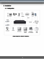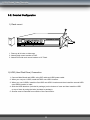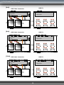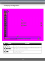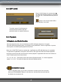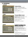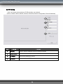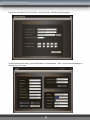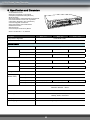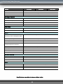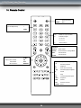
1
Ver 1.100 INSTALLATION & SAFEGUARDS All the safety and operating instructions should be read before operation. Environment Condition for Installation 1. To prevent electric shock or other hazard, do not expose this unit to rain, moisture, or dust. 2. Place this unit in a well-ventilated place and do not place heat-generating objects on this unit. 3. This unit should not be located in an area where it is likely to be subjected to mechanical shocks. Before You Start 1. Ensure the power switch is in the OFF position prior to installation. 2. Opening or removing the cover may expose you to dangerous voltage or other hazards. 3. Operate this unit within the range of room temperature and humidity. 4. Supply power through the type of power source indicated on the manufacturer’s label and with the power supply included in this unit. 5. Keep this unit out of direct sunlight and heat . 6. Make sure conductive material does not go into the fan hole. Notice 1. Before initial configuration or operation, first set TIME/DATE, and then set this unit to the FACTORY DEFAULT setting, and lastly HDD clear. Follow these steps in order. Otherwise it may cause non-recording on the HDD or non saving setting value. Or it may record, but you will not be able to search recorded data. 2. This unit is compatible with large sized HDD. 3. When setting RECORDING SETUP after installation, set not only RECORD CONFIGURATION, but also SCHEDULE SETUP. Setting Schedule setup is necessary as this unit records according to Record type & Schedule setup. Default setting value for Schedule setup is Continuous mode. 4. Stop recording before powering off this unit by entering setup menu. Powering off while recording may cause critical malfunctions such as Recording Error, Playback Error, or System Error. FCC Information This equipment has been tested and found to comply with the limits for a Class A digital device, pursuant to part 15 of the FCC Rules. These limits are designed to provide reasonable protection against harmful interference when the equipment is operated in a commercial environment. This equipment generates, uses, and can radiate radio frequency energy and, if not installed and used in accordance with the instruction manual, may cause harmful interference to radio communications. Operation of this equipment in a residential area is likely to cause harmful interference in which case the user will be required to correct the interference at his own expense. Changes or modifications not expressly approved by the party responsible for compliance could void the user's authority to operated the equipment under FCC rules. 2 CONTENTS CHAP. 1 General Information ---------------------------------------------------------------- 5 Package Contents & Description ---------------------------------------------------------------- 5 Function of Buttons ---------------------------------------------------------------- 6 2-1. Front Panel ---------------------------------------------------------------- 6 2-2. Rear Panel ---------------------------------------------------------------- 8 CHAP. 3 Installation ---------------------------------------------------------------- 10 3-1. Configuration ---------------------------------------------------------------- 10 3-2. Detailed Configuration ---------------------------------------------------------------- 11 1) Rack Mount ---------------------------------------------------------------- 11 2) HDD (Hard Disk Drive) ---------------------------------------------------------------- 11 3) Camera ---------------------------------------------------------------- 13 4) Audio ---------------------------------------------------------------- 13 5) Monitor ---------------------------------------------------------------- 14 6) Power Cable ---------------------------------------------------------------- 14 7) SPOT Output, Video Printer ---------------------------------------------------------------- 14 8) Others ---------------------------------------------------------------- 15 Display Configuration ---------------------------------------------------------------- 17 4-1. Display ---------------------------------------------------------------- 18 4-2. Main Menu ---------------------------------------------------------------- 19 4-3. Record, Playback Panel ---------------------------------------------------------------- 22 4-4. Panic Recording ---------------------------------------------------------------- 22 4-5. SEARCH ---------------------------------------------------------------- 23 4-6. PAN/TILT/ZOOM Control ---------------------------------------------------------------- 24 4-7. Data Backup (CD/DVD) ---------------------------------------------------------------- 24 4-8. Data Backup (USB) ---------------------------------------------------------------- 25 Operation ---------------------------------------------------------------- 26 5-1. System Login ---------------------------------------------------------------- 26 5-2. Factory Default ---------------------------------------------------------------- 26 5-3. Key Lock ---------------------------------------------------------------- 27 5-4. Playback ---------------------------------------------------------------- 27 1-1. CHAP. 2 CHAP. 4 CHAP. 5 3 CHAP. 6 DVR Setup ---------------------------------------------------------------- 28 6-1. General Operation ---------------------------------------------------------------- 28 6-2. SYSTEM Setup ---------------------------------------------------------------- 29 6-3. DISPLAY Setup ---------------------------------------------------------------- 32 6-4. RECORD Setup ---------------------------------------------------------------- 34 6-5. CAMERA Setup ---------------------------------------------------------------- 36 6-6. DEVICE Setup ---------------------------------------------------------------- 38 6-7. NETWORK Setup ---------------------------------------------------------------- 40 6-8. Language Setup ---------------------------------------------------------------- 42 Network Setup ---------------------------------------------------------------- 43 7-1. DVR Network ---------------------------------------------------------------- 43 7-2. DDNS ---------------------------------------------------------------- 45 7-3. Web Application ---------------------------------------------------------------- 46 Remote Viewer Program ---------------------------------------------------------------- 48 8-1. IRS Operation ---------------------------------------------------------------- 48 8-2. Backup Operation ---------------------------------------------------------------- 51 8-3. Transmitter Operation ---------------------------------------------------------------- 53 8-4. Player Operation ---------------------------------------------------------------- 59 CHAP. 9 Specification / Dimension ---------------------------------------------------------------- 62 CHAP.10 Remote Controller ---------------------------------------------------------------- 64 CHAP . 7 CHAP. 8 4 1. General Information 1-1. Package Contents & Description 1. DVR Main Unit 3. Power Cable 7. Rubber Pad 2. Remote Control 4. Power Adapter 5. User’s Manual 8. HDD Absorber 8. Batteries 9. Rack Mount Bracket HDD Bolts Contents 6. Software CD 10. Mouse Description 1. DVR Main Unit Stand-Alone DIGITAL VIDEO RECORDER 2. Remote Control Remote Control 3. Power Cable AC power supply to adapter 4. Power Adapter DC power supply 5. User’s Manual User’s Manual 6. Software CD Remote Viewer SOFTWARE 7. Rubber Pad Prevent DVR from slipping by attaching on the bottom of the unit 8. HDD Absorber Absorbing the mechanical shock of HDD against the case bottom 9. Batteries Batteries for Remote Control 10. Rack Mount Bracket / Bolts Rack M ount Bracket / 6 Bolts for fxing Rack M ount Bracket to DVR / 4 Bolts for fxing DVR with Rack M ount Bracket to 19” Rack / 8 Bolts for fxing HDD into DVR 11. Mouse DVR function control 5 2. Function of Buttons 2-1. Front 1 2 3 6 4 5 7 8 Name Function 1.LED Lamps Status of operation 2.Jog Shuttle Jog shuttle activate only when in Pause: Pressing Jog Shuttle button will pause playback. Rotating clockwise causes it to move into ever-faster forward speed, and counter-clockwise causes it to move into ever-faster reverse speed. In Setup Menu, its rotation Increases or Decreases value. 3.Function Key MENU Enter SYSTEM MENU PANIC Panic recording at continuous mode at highest quality (120ips, Highest, 1/1x) BOOKMARK Check the bookmark while playback for bookmark search. PLAY Playback recorded data on HDD AUDIO Select audio channel. Turn volume up/down K.LOCK Locking the key. To unlock, keep pressing the button for a few seconds and input password (Same password for Setup Menu) 4.LIVE View Control Key SEARCH Search recorded data on HDD STOP Stop Playback. PTZ Shift LIVE mode to PTZ control mode MODE Switch screen division from full screen to 16 split screen (in 1, 4, 9, 13, 16 sequence ) SEQ Auto camera image sequence in full screen mode PIP Picture In Picture mode FRZ Freeze Live display ZOOM Zoom image 6 Name 4-1.Control Key Function FUNC Main menu panel On/Off ESC Cancel selected menu panel + Increase setting value, page shift - Decrease setting value, page shift 5.Arrow key Navigate in the menu 6. USB Device For Firmware upgrade and USB backup 7.Camera Selection / PTZ Control 1~16 Button : Select camera channel in full screen mode 8.CD/DVD-ROM NEAR : FOCUS NEAR PRESET + : Increase PRESET NO. FAR : FOCUS FAR PRESET - : Decrease PRESET NO. WIDE : ZOOM IN PTZMENU : PTZ MENU POPUP TELE : ZOOM OUT F1 : USER 1 SET : PRESET SET F2 : USER 2 CLEAR : PRESET CLEAR F3 : USER 3 GOTO : PRESET GOTO F4 : USER 4 AUTO : AUTO SCAN F5 : USER 5 For Firmware upgrade and CD/DVD backup 7 2-2. Rear [Rear Panel for 4ch DVR] 2 1 5 11 3 4 10 6 7 9 8 12 [Rear Panel for 8ch DVR] 1 4 3 5 11 2 7 6 10 8 9 12 9 12 [Rear Panel for 16ch DVR] 2 3 10 5 4 1 6 11 7 8 8 Name 1 Function RS 485 Connection with PTZ Camera or other external devices using RS 485 RELAY Output Relay Output terminal SENSOR Input Sensor Input terminal 2 VGA 3 ETHERNET 4 RS-232C 5 Camera Input 6 Loop Out 7 Monitor Output 8 SPOT Output 9 DC Power DC 12V 6.67A Adaptor 10 PS2 Mouse Connection to PS2 Mouse 11 Audio 12 VGA Output to CRT or TFT LCD Monitors Connection to Ethernet devices Connection to external devices such as PC using RS-232C to control DVR Connection with NTSC/PAL Cameras Camera Loop out Connection with NTSC/PAL Composite Monitor Connection from Analog backup output to external devices Microphone input and Audio output POWER SWITCH Power ON/OFF Switch NOTE : You can not mix PAL and NTSC equipment. For example, you cannot use a PAL camera and NTSC monitor. 9 3. Installation 3-1. Configuration [ Typical Digital Video Recorder Installation ] 10 3-2. Detailed Configuration 1) Rack mount 1 2 3 1. Remove all 4 bolts on side caps. 2. Attach Rack mount bracket to DVR. 3. Attach DVR with rack mount bracket to 19” Rack. 2) HDD (Hard Disk Drive) Connection 1. Connect Main Board and HDD1 using IDE cable and HDD power cable. 2. When you use just 1 HDD, install the HDD onto HDD1 location. 3. When you use 2 HDDs, install the first HDD onto HDD1 location and then install the second HDD onto HDD2 location in order. 4. Stick the HDD absorber (included in package) on the bottom of case and then install the HDD on top of them by using the bolts (included in package). 5. Screws must be inserted from outside of the case bottom. 11 [4ch] HDD Fix HDD Cable Connection MAIN BOARD MAIN BOARD HDD1 HDD2 HDD1 ( MASTER1) [8ch] HDD2 (MASTER2) CD -RW ( MASTER ) x x x x x x x x x x x x x x x x x x x x x x x x x x x x x x x x x x x x HDD Fix HDD Cable Connection MAIN BOARD MAIN BOARD HDD1 HDD2 HDD1 ( MASTER1) [16ch] HDD2 (MASTER2) CD -RW ( MASTER ) HDD Fix HDD Cable Connection MAIN BOARD MAIN BOARD HDD1 HDD2 HDD1 ( MASTER1) HDD2 (MASTER2) CD -RW ( MASTER ) 12 3) Camera DC LEVEL V.P VIDEO CAMERA IN CH1 …… L OOP MO NITO R DC VIDEO LENS CH16 SPO T AC24V/DC12 Rear view of CAMERA DC12V Connect cameras to the camera input on rear panel of DVR marked CAMERA IN. 4) Audio - Audio Input 1. 4ch Audio Input is available for MSD-1600, 2ch for MSD-800, 1ch for MSD-400. 2. Connect Audio Input as needed for camera channels. 3. Audio channel 1 is assigned for camera channel 1~4, audio channel 2 for camera channel 5~8, audio channel 3 for camera channel 9~12 and audio channel 4 for camera channel 13~16. 4. Audio input should be connected according to assigned camera channels for audio recording. - Microphone Input 1. 1 Microphone Input is available. It does not record microphone input. 2. Microphone is to support TWO-WAY Audio, for communication with remote user. - Audio Output 1. 1ch Audio Output is available. 2. Selected Audio channel at DVR will be output. 13 5) Monitor CAMERA IN …… CH1 MONITO R CH16 V IDE O A IN OUT V IDE O B IN OU T V IDE O C IN OUT SPO T L OOP Connect the video output marked MONITOR to VIDEO-IN of Main Monitor. 6) Power Cable Connect DC 12V, 6.67A Adaptor to the back side of Power Jack for right operation of 2HDDs and CD Recorder. Before turning on, be sure all necessary devices such as Power adaptor, cameras and Monitor are connected properly to DVR! Notice To avoid accidental deletion of HDD data, please make sure to press MENU button before powering off the unit. This takes the unit out of recording mode for safe shutdown. 7) SPOT CAMERA IN CH1 …… L OOP MO NITO R CH16 SPOT Connection with the spot monitor as needed. 14 4. Display Configuration 2 3 1 No Contents Description 1 Display Display Date/Time, HDD Status, HDD recorded space, available remaining days, and audio channel 2 Main Menu Click with mouse : SPLIT, CHANNEL, AUDIO, FRZ, SEQ, ZOOM, PIP, PTZ, SETUP, PANIC, PLAY, SEARCH 3 LIVE Live screen of each channel Camera Title & Status 17 4-1. Display 1) Date/Time Live mode : shows the current date & time Playback mode : shows the recorded date & time of the playback image 2) AUDIO Icon The number in the icon indicates which Audio channel is on. In case Audio channel 1 is ON, appears. 3) Record Icon Displays the current recording mode. In case of Continuous Recording Mode, appears. 4) HDD Overwrite appears when the HDD overwrite mode is selected. 5) HDD Space The HDD recorded space is marked in red on the time bar. The available remaining days/time at the current record mode is also displayed. 18 4-2. Main Menu 1) Split Screen Screen division panels display various screen viewing options: Full screen mode : Channel Bar pops up 9 Channels Split 4 Channels Split 2) 16 Channels Split Display Channel Selection Display Channel Selection Panel views, and selected channel displays in full screen mode. (Channels are also selectable in ZOOM, PTZ, and FREEZE mode.) 3) AUDIO Channel Selection Audio Channel Selection Panel controls. (1ch output for 4ch DVR, 2ch output for 8ch DVR, 4ch output for 16ch DVR) 4) SEQ (Sequence) Displays full screen mode images in sequence In case of 4 Split, 1,2,3,4 -> 5,6,7,8 -> 9,10,11,12…… images sequenced. CH04 CH03 CH02 ● ● ● CH01 19 5) FRZ (Freeze) Click FRZ to pause with icon. Click each channel to pause with 6) icon. PTZ (PAN/ TILT/ ZOOM) Click the PTZ button, and the PTZ Controller panel will pop up as shown below. 7) OPEN IRIS OPEN SET PRESET SET CLOSE IRIS CLOSE CLEAR PRESET CLEAR WIDE ZOOM OUT GOTO PRESET GO TO TELE ZOOM IN AUTO AUTO SCAN NEAR FOCUS NEAR Arrow PAN / TILT FAR FOCUS FAR No. PRESET No. ZOOM In LIVE mode, images Zoom in X2. Move selected frame by mouse control. Click ESC to exit zoom mode. 8) PIP One channel displays on the full monitor screen while another small screen displays on the inset window. CAM01 -Small screen can display in sequence according to preset interval. - Full screen can be shifted to next channel by clicking the full screen or by clicking the channel number. CAM02 20 9) Setup Click SETUP button to go to the setup menu. (See Chapter 6 for more details.) 10) SEARCH Its function is to search the recorded data easily and to playback. Search by Time/Date, Percentage of HDD availability, Event, and Bookmark list search available. (See Chapter 4-5 for more detailed instruction) 11) PLAY While in LIVE mode, click the PLAY button and it will playback recorded images. The Control Panel pops up and assists in flexible playback operation: play forward/reverse, previous/next, fast forward/reverse, and pause. 13) Panic Recording In case of an emergency, click the Panic Record icon to activate the panic recording. appears and it starts recording at continuous mode at highest quality. (See Chapter 4-4 for more details) 21 4-3. Record, Playback Toolbar 1 No 2 3 Function 4 5 Details 6 7 No 8 Function 9 10 11 Details 1 Move to Move to Beginning of Recording and Playback 7 Decrease Playback Speed In fast playback : decrease playback speed. In pause : it plays back frame by frame 2 Increase In reverse playback : 8 Increase Playback Speed In forward playback : 3 Decrease In fast playback : decrease playback speed. In pause : it plays back frame by frame 9 Move to End Move to the end of recording and stop 4 Reverse Playback in Reverse Direction 10 BOOKMARK Check and save bookmark point while playback 5 Pause Pause Playback 11 EXIT Exit Playback Mode. 6 Playback Playback Beginning Playback Speed Playback Speed Increase playback speed Playback Increase playback speed 4-4. Panic Recording 1) Schedule recording & Emergency recording Default setting is Schedule recording: continuous recording mode. In case of emergency, click the Emergency Record button and it begins recording at highest quality level. (Record LED lights on DVR) Panic Recording : Records at the highest quality on a continuous recording mode. Schedule Mode : Records according to the recording settings in the RECORD SETUP & SCHEDULE SETUP menu. To return to Schedule Recording mode, click ‘STOP’ button. 2) When the system does not record: - when cameras are NOT connected. - when the HDD is full and the overwrite mode is not selected. - when factory the default and the HDD clear function was not run before recording. - when in Schedule recording mode and it is set not to record at the time. 22 4-5. SEARCH Searching is available in 3 different methods. Click button, and search window will popup as below: 1) Search by Date/Time - Search by Time and Date as entered. You can change the target Date/Time values by clicking “+” and “-”. 2) Search by Percentage of HDD - Search by Percentage of HDD Search by Percentage of total recorded data on HDD. You can change the target Date/Time values by clicking “+” and “-” or anywhere in the percent search bar. It starts playback from the selected Date/Time or from the point marked on the percent search bar. 3) Search by Event List - Search by event list which tracks Motion Detection, Alarm Input, and/or Video Loss. Select any event shown on the list first and click “PLAY” button to play it. Playback will start from the beginning of the selected event. 4) Search by BOOKMARK List - Search by bookmark list. While in playback mode, if you want to remember a certain point of the recorded data, press the “BOOKMARK” button and the time and date will be added to the bookmark list. Select any recorded data on the bookmark list and click the “PLAY” button to play. 23 4-6. PTZ Control Push [PTZ] button on the DVR to activate the PTZ mode. Button Description Button Description 1 / NEAR FOCUS NEAR 10 / PRESET+ PRESET No. + 2 / FAR FOCUS FAR 11 / PTZ MENU PTZ MENU 3 / WIDE ZOOM OUT 12 / F1 ~ 13 / F5 Function 4 / TELE ZOOM IN UP TILT UP 5 / SET PRESET SET DOWN TILT DOWN 6 / CLEAR PRESET CLEAR LEFT PAN LEFT 7 / GOTO PRESET GOTO RIGHT PAN RIGHT 8 / AUTO AUTO SCAN +- Select Channel 9 / PRESET- PRESET No. - 4-7. CD/DVD Backup Please Login and click “BACKUP/UPGRADE” icon and click “USB BACKUP” button. 1. Insert an empty CD-R media into CD writer and select time and date you want to begin backup. (Start & End time and date in HDD sub-menu is not editable. It only shows the start and end time and date of total recorded data.) 2. After selecting Start time and date, select BACKUP SIZE, and it will display the end time. The End time and date will be calculated automatically as per start time and the selected backup data size. (To backup in several CDs, set size in SPLIT TO FILE) 3. Click BACKUP START to start backup. 4. When the burning process is completed, the CD-RW will open automatically, and the start time will be set automatically to the end time of burned data for continuous backup process. The End time will be calculated automatically as per the selected backup data size in previous backup. To continue backup, insert new CD-R media and repeat above procedure. To stop backup, click MENU button or close the window. 5. Install BACKUP CD PLAYER with the CD included in the accessory pack. Playback of the recorded data is available now. (See Chapter 6-7 for more information) 24 4-8. USB Backup Please Login and click “BACKUP/UPGRADE” icon and click “USB BACKUP” button. 1. Insert the USB memory stick on the USB port of the DVR and select the time and date you want to begin backup. (* Start & End time and date in HDD sub-menu is not editable. It only shows the start and end time and date of total recorded data.) 2. After selecting the Start time and date, select BACKUP SIZE, and it will show end time. The End time and date will be calculated automatically as per the start time and the selected backup data size. 3. Click BACKUP START to start backup. 4. When the backup process is completed, the start time will be set automatically to the end time of backup data for continuous backup process. The end time will be calculated automatically as per selected backup data size in previous backup. 5. Install BACKUP CD PLAYER with the CD included in the accessory pack. Playback of the recorded data is available now. (See Chapter 6-7 for more information) 25 5. Operation 5-1. System Login 1) To enter system menu, press the MENU button. Select the user name, input the password and click the OK button. 5-2. Factory Default * Check if all channels are being displayed properly before the first operation. Log into the Main Menu and set Time/Date and run factory default and clear HDD. ** Starting recording without factory default and clear HDD may cause a malfunction. ( See chapter 6-6 ) ( See chapter 5-2) 26 5-3. KEY LOCK Press K.LOCK button for several seconds and then the message appears to confirm. If you click “OK”, it will lock all the key function of DVR. appears on the screen while DVR is under the Key Lock mode. To unlock, press K.LOCK button for several second and then input the password (same as system password) 5-4. Playback 1) Playback, Jog / Shuttle Function Click the playback button, the recorded data on HDD will begin playback at X1 speed. Click the backward playback button, It will being to play backwards. Use the Jog/Shuttle to pause, lower speed or Increase speed playback and pause. Press the ‘J.SHUTTLE’ button to activate the Jog/Shuttle, the LED will blink when it is available. To operate the Jog/Shuttle, turning the control knob to the right will control fast-forward playback, turning the control to the left, will control its reverse playback. Jog/shuttle will control one camera at a time. Shuttle speeds are shown below. 1/2, 1/4, 1/8, 1/16 : The speed is lower than Normal Playback speed. 1X : Normal playback speed. 2, 4, 8, 32 : The speed is faster than Normal Playback speed. 2) BOOKMARK Function While in playback mode, if you want to remember a certain point of the recorded data, press “BOOKMARK” Button or click the icon. And then the time and date will be added to the bookmark list. 27 6. DVR Setup 6-1. General Operation SETUP GROUP GROUP CONTENTS SYSTEM INFORMATION, UPGRADE, USER AUTHORITY, PASSWORD, BUZZER AUDIO, REMOTE CONTROL, FACTORY DEFAULT DISPLAY DATE/TIME, DISPLAY SETUP, VGA, INTERVAL, LANGUAGE RECORD RECORD SETUP, MOTION, SCHEDULE, HOLIDAY CAMERA CAMERA TITLE, COLOR ADJUSTMENT, ACTIVATION, ALARM PTZ SETUP, PTZ SPEED, EVENT POPUP DEVICE CLEAR HDD, CD/DVD BACKUP, USB BACKUP, RS-232C NETWORK ETHERNET, DDNS, PPPoE 28 6-2. SYSTEM Setup 1) INFORMATION To display the System Information • Click ‘SAVE’ or ’EXIT’ to exit. 2) UPGRADE To access the Menu for a USB Upgrade. •Insert an USB memory stick which has the firmware ( to be upgraded ) into the USB port on the front. •Go to “UPGRADE” and then it will automatically detect the USB memory stick. •Click “START” to start upgrading. 3) USER AUTHORITY To Set the Authority level of each user. • Review the checkbox of contents for MANAGER & USER menu. The corresponding user grade will have authority to access the setting Menu as checked. •Click OK to save this setting. •Click DEFAULT to return to the original setting. 29 4) PASSWORD To Program the Password for each user level. Select user level, and set USER PASSWORD. Set different passwords for different user levels. Click OK to save the setting. Click CANCEL to cancel. 5) BUZZER To Program the parameters for the buzzer (On/Off). Review checkbox for events that will activate the buzzer. •KEY : when button on the key panel is clicked or pressed. •VIDEO LOSS : when video signal is lost. •ALARM ACTIVE : when alarm is activated. •MOTION DETECT : motion is detected. •Click OK to save this setting. •Click DEFAULT to return to the original setting. . 6) AUDIO To set the audio output volume. •AUDIO VOLUME : Set the output volume for each channel. •Click OK to save this setting. •Click DEFAULT to return to the original setting. . 30 7) REMOTE CONTROL To Set the Remote Controller for DVR. •The DVR can be controlled remotely with IR remote controller (Included). •Setup for number of remote control available (All, 1~6). •Click OK to save this setting. •Click DEFAULT to return to the original setting. . 8) FACTORY DEFAULT To re-set the DVR back to the original manufactures specifications or Factory Default . •Review the checkbox of contents to reset. •Click OK to run factory default. •Click CANCEL to return to initial setting. 31 6-3 DISPLAY Setup 1) DATE/TIME To set time and date of DVR system. •Set the time and date by selecting your TIME ZONE. •Set the Time Display Format. •Check checkbox DAYLIGHT for Saving Time mode. • (DST) •Click OK to save this setting. •Click DEFAULT to return to the original setting. 2) DISPLAY SETUP Review the checkbox of contents to be displayed on Live and Playback screen. •DATE/TIME : Current time / Record time •ICON STATUS : LIVE status icon •DVR STATUS : DVR status icon •REC/PLAY BAR : HDD Bar •CAMERA TITLE : Camera Title •Click OK to save this setting. •Click DEFAULT to return to the original setting. 3) VGA To Program the VGA OUT. •VGA : Connection ON/OFF. •RESOLUTION : Set Resolution •FREQUENCY : 60Hz, 75Hz •Click OK to save this setting. •Click DEFAULT to return to the original setting. . 32 4) INTERVAL To set the interval for channel sequencing. •SEQUENCE : Camera channel time interval. •PIP : PIP channel sequencing time interval. •SPOT MONITOR : SPOT MONITOR sequencing time interval. •EVENT UPDATE TIME : EVENT update interval. • •Click OK to save this setting. •Click DEFAULT to return to the original setting. . 5) LANGUAGE To select language. •Click “OK” to save the setting. 33 6-4 RECORD Setup 1) RECORD SETUP To set the recorder configuration. •CHANNEL: Channels of the 4-camera groups. •QUALITY : Recording quality of the selected channels of 4-camera group. • FPS : Frames per second • Pre Alarm : Record data 0~5 seconds before the alarm occurs •*Notice : In case of sudden power off while in PreAlarm mode, up to 5 seconds of data loss may occur. •Click OK to save this setting. •Click DEFAULT to return to the original setting. 2) MOTION The Menu for DVR Motion Detection Programming. •Select CHANNEL •SENSITIVITY : sensitivity LOW ~ VERY HIGH •MOTION DURATION: The time duration of motion detection. •MASK ZONE : Click MASK ZONE to select or clear blocks. •Click OK to save this setting. •Click DEFAULT to return to the original setting. 3) SCHEDULE To Set the Schedule Recording Mode. •Appoint Schedule recording by Day and Hour. •MOTION, ALARM, MOTION+ALARM or CONTINUOUS recording mode selectable. Note: In case of emergency, click the Panic button which will start recording at CONTINUOUS MODE at the highest resolution. Unless otherwise specified, it records according to this Schedule Record Setup. •Click OK to save this setting. •Click DEFAULT to return to the original setting 34 4) HOLIDAY To set the Holiday Schedule: Setting national holidays, weekly security hours or custom holidays on the calendar to record. •Set date on SET HOLIDAY and click ⇒, and set date will be listed on HOLIDAY LIST. •It will record as setting for Sunday in Schedule Record Setup. •Click OK to save this setting. •Click DEFAULT to return to the original setting. 35 6-5. CAMERA Setup 1) CAMERA TITLE Programming the title of each camera. Left click any place one the screen. Then, the virtual keyboard panel pops up. Enter title and click ENTER. - Click OK to save the setting. - Click DEFAULT to cancel. 2) COLOR ADJUSTMENT To Adjust the Camera Image Color. •BRIGHTNESS : 0 ~ 255 •CONTRAST : 0 ~ 255 •SATURATION : 0 ~ 255 •HUE : 0 ~ 255 •Click OK to save this setting. •Click DEFAULT to return to the original setting. 3) ACTIVATION To set the Camera Activation. •STATUS : Camera type: NTSC/PAL/LOSS. •COVERT : Check the checkbox of camera channel not to display. •REC : Check checkbox of camera channel to Record. •Click OK to save this setting. •Click DEFAULT to return to the original setting. 36 4) ALARM To program an alarm sensor connected to DVR. •Set input type and dwell time for each channel. •Select between N.O. and N.C. (Normal Open : NO, Normal Close : N.C.) •Click OK to save this setting. •Click DEFAULT to return to the original setting. 5) PTZ SETUP To Program a PTZ Camera. •CHANNEL : Selection connected PTZ •PROTOCOL : Selection Camera Model •ID: ID Value for PTZ Camera •BAUD RATE : PTZ SIGNAL Transmit rate •PAN : Horizontal movement Speed •TILT : Vertical movement Speed •ZOOM : Zoom In/Out Speed •FOCUS : Focus Near/Far Speed •Click OK to save this setting. •Click DEFAULT to return to the original setting. 6) EVENT POPUP To Program an Event Popup. •Select the camera channel •Select POPUP On or Off •EVENT : Check the checkbox of MOTION and/or ALARM •Dwell Time : The period of time for the popup in case of Event. •Click OK to save this setting. •Click DEFAULT to return to the original setting 37 6-6. DEVICE Setup 1) CLEAR HDD The Menu to erase /clear the HDD. •Displays starting time and the ending time of the currently saved data on HDD. •After pressing the ‘START’ button, account, and password of DVR, an input window pop up. •Then, after inputting the number, the HDD changes to the CLEAR Status. •OVERWRITE : When HDD is full, the DVR automatically overwrites from the beginning of HDD. •Click OK to SAVE and EXIT or CANCEL to EXIT. 2) CD/DVD BACKUP How to Backup via CD/DVD-RW. •Review the Display Start & End time of total recorded data on HDD which is displayed at the top screen. •Input the date/time of data you wish to backup and click the SELECT button to check total backup data file size. •If total backup data size is bigger than CD/DVD storage, the End time will be determined automatically. •Click START to start backup. How to Backup via USB. 3) USB BACKUP •Review the Display Start & End time of total recorded data on HDD which is displayed at the top screen. •Input the date/time of data you wish to backup and click the SELECT button to check total backup data file size. •If total backup data size is bigger than USB storage device , the End time will be determined automatically. • the Backup data file size is adjustable to USB storage size. •Click START to start backup. 38 4) RS-232C To program the settings for the RS-232C port. •BAUD RATE : 2400 ~ 115200 •LENGTH : 5 ~ 8 •STOP BIT : 1 ~ 2 •PARITY : NONE, ODD OVEN •FLOW CONTROL : NONE, SOFTWARE, HARDWARE •Click OK to save this setting. •Click DEFAULT to return to the original setting. 39 6-7. NETWORK Setup 1) ETHERNET To Setup the DVR Network. •DYNAMIC IP : Check checkbox to enable connection via Cable Modem with Dynamic IP. •STATIC IP : Check checkbox to enable connection via Stable IP Click OK to save the settings. Click EXIT to cancel. (Refer to Chapter 7-1 for more details) 2) DDNS To Program the DDNS Server Connection. •DDNS SERVER : DDNS Server address. •DVR NAME : Program the DVR name that it is to be registered to the server. •INTERVAL: Program how often the DVR information is forwarding to DDNS SERVER. •Click OK to save the settings. •Click EXIT to cancel. (Refer to Chapter 7-2 for more details) 3) PPPoE To Program the PPPoE Connection. (In case of using local DSL) : When connecting to the local network through an external modem. •ID: Please enter the ID which you received from the local DSL service company. •User Password : Please enter the PW which you received from local DSL service company. •Retry Count: Program the number of retry’s it will attempt. •Retry Interval: Program the time interval between retry attempts. •Click OK to save this setting. •Click DEFAULT to return to the original setting. (Refer to Chapter 6-7, 7-1 for more details) 40 4) WEB GUARD Programming the web server port • WEB GUARD : Activate the WEB GUARD function by checking the box. •WEB PORT : Setting web port number •Click OK to save setting. •Click EXIT to cancel. (Refer to Chapter 7-4 for more details) 5) NOTIFICATION Programming the EVENT NOTIFICATION •RETRY COUNT: Setting of retry number •SEND INTERVAL: Setting of sending interval - TIME(MIN) : Sending event every setting time(min) - EVENT COUNT : Sending event when reaches setting count number •SEND CONDITION : Type of Event Activation. •Click OK to save setting •Click EXIT to cancel (Refer to Chapter 7-5 for more details) 6) SMTP SERVER SETUP Programming the SMTP SERVER •ID ADDRESS: Input the address of SMTP server. •PORT : Input SMTP PORT •AUTHENTICATION : Setting of authentication •ACCOUNT : Input account number •PASSWORD : Input password •Click OK to save this setting. •Click DEFAULT to return to the original setting. (Refer to Chapter 7-5 for more details) 41 7) E-MAIL To Program E-MAIL NOTIFICATION •LOCATION : Information of mail title •SENDER : Input address of sender •RECIPIENT: Input e-mail address’ of recipients Available up to 3 persons. (Refer to Chapter 7-7 for more details) 6-8. LANGUAGE 1) LANGUAGE - Select language. - Click “OK” to save setting. 42 7. Network Setup 7-1. DVR Network Setup Please contact your local network service provider for information below: - Upload Speed : to predict frame rate via network. - Download Speed : to predict frame rate via network. - Addressing : to determine which scenario to follow. - Router ON Site or Just Modem : to determine which scenario to follow. * NOTE : If the provider is using PPPoE (usually D 니 providers), you MUST have a IP Share installed on site, and follow 3) Dynamic IP of PPPoE (DSL) for DVR setup and access. * Verify if Internet accessible after installing any new equipment (routers, switches, modems, etc.) PC’s TCP/IP Setup Fill out the information below before configuring DVR if applicable: Choose PC connected to the network and determine its TCP/IP setting. IP address : __________________________________________________________ ex) 192.168.1.5 Subnet Mask : ________________________________________________________ ex) 255.255.255.0 Default Gateway : _____________________________________________________ ex) 192.168.1.1 Refer to following scenarios 1) ~ 3), and identify which scenario your current network falls within and follow instructions for configuring and accessing your DVR via TCP/IP. 1) Static IP User input IP address assigned from ISP company in IP CONFIG SETUP. 1) Verify if IP address is OK with your PC before connecting DVR. 2) Connect static IP LAN cable to DVR after verification. 3) Enter into [MENU]-[NETWORK SETUP]-[IP CONFIG]. 4) Select STABLE IP and set assigned IP address. 5) Input GATEWAY assigned from ISP company. 6) Input SUBNET MASK. 7) Exit MENU. 8) Verify if MAC address starts with 00-0A-A2…. 9) Set IP port in CONNECTION SETUP. (50000 recommended) 10) Turn off Modem or Router provided by ISP company, and turn on again. (This process is to reset client’s MAC from ISP company. Wait for 30 sec after turning on.) 11) Access DVR with Transmitter Program. * If access via Transmitter fails, check 1), 5), 6) & 9) again. 43 2) Dynamic IP of Cable Method Select DYNAMIC IP from DVR’s TCP/IP SETUP and an IP address will be assigned from ISP’s DHCP server. 1) Verify if the IP address is OK with your PC before connecting DVR. 2) Connect the dynamic IP LAN cable to DVR after verification. 3) Turn off Modem provided by ISP company, and turn it on again. (This process is to reset client’s MAC from ISP company. Wait for 30 sec after turning it on.) 4) When modem functions properly, turn off DVR and turn it on again. 5) Enter into [MENU]-[NETWORK SETUP]-[IP CONFIG]. 6) Select DYNAMIC IP and click refresh button. 7) Exit MENU. 8) Verify if the MAC address starts with 00-0A-A2…. 9) Set IP port in CONNECTION SETUP. (50000 recommended) 10) Access the DVR with Transmitter Program. * If access via Transmitter fails, check 1), 3) & 4) again. 3) Dynamic IP of PPPOE Method Enter PPPOE setting in the DVR’s TCP/IP SETUP 1) Verify if the IP address is OK with your PC before connecting the DVR. 2) Connect the dynamic IP LAN cable to DVR after verification. 3) Turn off Modem provided by ISP company, and turn on again. (This process is to reset client’s MAC from ISP company. Wait for 30 sec after turning on.) 4) When modem functions properly, turn off DVR and turn it on again. 5) Enter into [MENU]-[NETWORK SETUP]-[PPPOE]. 6) Input the ID & PASSWORD assigned from ISP 7) Exit MENU. 8) Verify if the MAC address starts with 00-0A-A2…. 9) Set IP port in CONNECTION SETUP. (50000 recommended) 10) Access the DVR with Transmitter Program. * If access via Transmitter fails, check 1), 3) & 4) again. 44 7-2. DDNS 1. Go into [Menu] -> [NETWORK] -> [DDNS]. 2. Click the check box of DDNS and Input the domain which you want to Register to DDNS. 3. Click OK to request the registration. NOTE : When entering a domain name already registered on DDNS server, an error massage displays 45 7-3. Web Application Entering the IP address of DVR or the Domain you registered on DDNS server, you can connect to the web application which support IRS (Remote Software) function. Notice : When you firstly use web application, please click “yes” for ActiveX control installation. DVR SETUP Change DVR setting remotely over network. BACKUP Backup Recorded Images from DVR to PC. PLAYER Playback backup data on PC. TRANSMITTER Control DVR remotely as if controlling the local unit DVR. 46 (Notice- For security reasons, if connection is not available, change the setting of internet browser as below. (Tools -> Internet Options -> Security) ) ① ③ ④ ② ③ ④ ⑤ Click ⑥ www.h264ip.com Leave this check box empty ⑦ 47 8. Remote Viewer Program 8-1. IRS Operation 1) IRS (Integrated Remote Station) Display 1 No. 2 3 Button 4 Function 1 IRS Setup Input Information for IRS network connection. 2 DVR Setup Change DVR setting remotely over network. 3 BACKUP Backup Recorded Images from DVR to PC. 4 PLAYER Playback backup data on PC. 5 TRANSMITTER Control DVR remotely as if controlling the local unit DVR. 48 5 2) IRS Setup 3 1 2 4 No. Button Function 1 ADD / PORT / LOCATION Input IP address and port number manually. Input the location of DVR 2 ID / PASS Input ID and Password of DVR. 3 UPDATE / DELETE Update the new setup, Delete the selected setup. 4 SAVE / OK Save and select the sight information from the list. 49 3) DVR Setup - User can change some settings of DVR remotely over network. (Active, Camera, Alarm, Buzzer, Interval, Password, Record Configuration, Record Schedule) 1 2 3 4 No. Button Function 1 MANUAL Select to input IP address and port number manually 2 DDNS / PORT Input IP address and port number of DVR 3 ID / PASS Input ID and password of DVR 4 CONNECT Click to connect to DVR. 50 8-2. Backup Operation 1) To execute Backup, input IP Address & Port and click ‘Connect Test’ Button. 2) After Connect Test is done, you can see ‘Success Connect Test!’ message. Then, click ‘Lock’ button and click ‘Set Backup Time’ Button. 51 3) Now you set ‘Start Time’, ‘End Time’, ‘Save File Path’, ‘File Size’ and click ‘Apply’. 4) After finishing time setting, click ‘Start Backup’ to start Backup. Then, you can see the Backup on the Path that you chose. 52 8-3. Transmitter Operation 1) Transmitter Display - TRANSMITTER : Program that enables connection to DVR via TCP/IP to see live screen and to control DVR. 12 14 13 7 10 11 1 9 2 4 3 5 6 8 No. Button Function 1 Connect Connect DVR via network 2 Disconnect Disconnect DVR connection via network. 3 Setup Change or set DVR system menu. 4 Search Search recorded data from HDD of DVR. (Date/Time Search, Event List) 5 Main Key Panel Pop up panel to control CH, REC, PLAY, STOP. 6 Two Way Audio Enable Two Way Audio between DVR and Transmitter. 53 No. Button Function 7 System Information Display DVR connection and System operation information. 8 PTZ CH Select the channel number connected to PTZ Camera. 9 ZOOM Zoom In/Out operation of PTZ Camera. 10 FOCUS Focus Near/Far operation of PTZ Camera. 11 PTZ PTZ ON : Pan/Tilt control of PTZ Camera. OFF: Function as arrow keys. 12 EXIT EXIT the transmitter. 13 User Input IP, PORT, ID, PASSWORD of remote DVR. 14 Date/Time Display Date/Time of DVR. 2) Transmitter – Search 1 2 3 4 5 6 7 [Search – Percent/Date] 54 8 9 [Search –Event List] 10 [Search –Bookmark List] 55 No. Button Function 1 Percent / Date Open window for Percent/Date search. 2 Event List Open window for Event List search. 3 Bookmark list Open window for Bookmark list searech. 4 Start / End Display Start and End time of recorded data on DVR. 5 Search by Time/Date Search by Time and Date as entered. 6 Search by percentage Search by Percentage of total recorded data on HDD. of HDD 7 OK Start playback. 8 CANCEL Close Search window. 9 Event List Index Show Event Lists received from DVR. Double click a list to start playback or click OK. 10 Bookmark List Index Show Bookmark Lists received from DVR. Double click a list to start playback or click OK. 56 3) Transmitter – Main Key 13 1 2 3 4 5 6 7 8 9 10 11 12 No. Button Function 1 Channel Select the channel number of camera to be displayed. 2 Division 4ch, 9ch, 16ch Division. 3 Record Force Emergency Record. 4 Play Playback recorded image on HDD. 5 Stop Stop Emergency Record or stop playback. 6 Mode Screen division mode in 1ch, 6ch, 8ch, 9ch, 13ch, 16ch. 7 Sequence Full screen image displays in sequence. 8 PIP Picture In Picture. 9 Un FRZ Continue playback from FREEZE. 10 Zoom Zoom In image. 11 Pause Stop playback for a short period of time. 12 -/+ Up/Down button for volume, channel, page. 13 Exit Exit Main Key Panel Button 4) Transmitter – PLAY Panel |< Move to the beginning of recording << Increase reverse playback speed <| Decrease reverse playback speed < Reverse playback x1 || Pause > Playback x1 |> Decrease playback speed >> Increase playback speed >| Move to the end of recording EXIT 57 Function Exit Playback Mode 5) Transmitter – Setup Page SETUP - STREAM Choose pre-setting for some specific network condition(128K, 256K, 512K) Or choose “CUSTOMISE” for setting as you want. Twoway Audio Choose the audio input from DVR for when Twoway Audio activated. 58 8-4. Player Operation 1) Player Select Please click “HIGH SPEED PC” or “LOW SPEED PC” according to your PC’s specification. “HIGH SPEED PC” supports all channel Playback simultaneously. “LOW SPEED PC” supports up to 4channel playback simultaneously. NOTE Recommended PC specification for “HIGH SPEED PC” is as below: Processor Type : Pentium Core2 DUO or better Memory : 1GB minimum 59 3) Player – Channel, Edit, AVI Save Panel 1 2 3 5 4 8 6 9 7 No. Button Function 1 1Ch ~ 16Ch In full screen mode, select 1 channel to be displayed. 2 Contrast In 4 split screen mode, select 4-channel group to be displayed. Adjust contrast of still image in full screen mode. 3 Bright Adjust brightness of still image in full screen mode. 4 Sharp Adjust sharpness of still image in full screen mode. 5 Image Save Save still image in image file in full screen mode. 6 Image Print Print still image in full screen mode. 7 AVI Save Option Select channel, frame rate & size to convert into .avi file. 8 Start Start saving data in .avi file format. 9 Stop Stop saving data in .avi file format. 61 9. Specification and Dimension • H.264 Hardware Codec • Real-Time Live Display in all Channel • Pentaplex (Playback/Recording/Ethernet) • Multi Language • Remote monitoring and Download through Network • Convenient Search Function with Jog/Shuttle • VGA Option (Supporting TFT LCD Monitor) • Firmware Upgrade via USB Port • Easy PTZ Camera Control with Mouse • Password Protection • Remote Control • User Friendly Environment by Mouse • Power 110-240 VAC, 1.5A, 60/50Hz Contents MSD-400 MSD-800 Compression Algorithm MSD-1600 H.264 Dual Codec Audio G.726 or mp2 General Feature Signal Format NTSC or PAL (Auto Detect) Video In 4CH 8CH Out Loop Out Main, Spot, VGA 4CH 8CH Video Compression Rate Audio 16CH 3 Steps Selectable In 1CH 2CH Out Alarm 16CH In 4CH 1CH 4EA 8EA Out 16EA 1 NO/NC Storage 2EA S-ATA HDD Recording Speed 704x480 (704x576) - (NTSC / PAL) - 704x240 (704x288) 352x240 (352x288) 120 (100) ips 352x120 (352x144) 240 (200) ips - Resolution of Motion Detection Area Area division : 16x12 Detection Division : 32x24 Search Mode Date/Time, HDD%, Event, Bookmark Recording Mode Schedule (Time, Motion, Alarm) Holiday, Panic, Pre-Event Display Speed Real-Time Multi Language English, Spanish, French etc. 62 480 (400) ips Contents MSD-400 MSD-800 PIP 1, 4, 9, 16, PIP Zoom Digital Zoom x2 Security MSD-1600 Key Lock Recording & Playback Multi-tasking Quadplex (Live, Playback, Recording, Ethernet) Multi Channel Playback Available Event Log Information Available Pre-Alarm Available Alarm / Relay Video Loss Alarm Available Motion detection Alarm Available Network Remote S/W Integrated Romote Station : Monitoring, Search & Playback, Backup Internet Explorer support Available (No need to register) DDNS Support Yes CMS Yes (Central Management Software) Simultaneous remote user access 4 persons or more Network Speed Value Selectable Remote Setup Available Data Export Own File Format Back-Up & Archiving CD-RW Option DVD-RW Yes USB Port USB 2.0 Others Operation Mouse / Remote control / Key Button PTZ Control RS-485 Menu GUI Specifications are subject to change without notice. 63 10. Remote Control DVR ID (For multiple users) REC Panic Recording MENU Menu DVR1 ~ DVR6 Select CH / Input number 1~9 indicates 2 digits 0 ‘0’+’0’=’10’ ‘0’+’1’=’11’ <No functions> +- SEARCH Search Menu AUDIO Audio On/Off MODE Screen Division / Change Mode ESC <No functions> FUNC <No functions> Move menu items & change value ▲◀▶▼ Enter menu & select PTZ On/Off <No functions> OK PTZ I◀ Playback from beginning BACKUP ◀ Reverse playback ▶ Playback ▶I Move to end and stop ◀◀ Decrease playback speed II Pause ■ Stop ▶▶ Increase playback speed SEQ Sequence FRZ Freeze PIP Picture In Picture ZOOM Zoom 64 Real-time playback / USB backup H.264 Hardware Codec