1
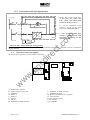
Block diagram components
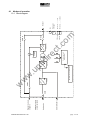
The UPS consists of the following subassemblies:
RECTIFIER
.c
om
The rectifier represents the input stage and transforms the alternating voltage from the mains supply in direct voltage.
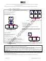
From the display panel can be programmed start
black out
up of the rectifier in particular:
input
- the start up delay t0 –t1 from 0 to 120s
(that allows to a not contemporary starter more UPS voltage
connects you to the same mains)
- power walk-in t1 – t2, from 0 to 120s
setting
(can be used a smaller Motor Generator size in UPS
setting
input).
input
current
The functions carried out by the rectifier are the
following:
supplying the inverter with direct
current.
automatically charging the battery.
optimize the input power factor with a
automatic battery charge system.
t1
t
t2
ct
t0
t
.u
ps
di
re
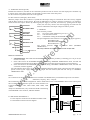
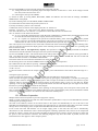
The cyclical battery charging is done in two phases.
The first phase recharge the batteries with limited current and increasing voltage (to the value of charge voltage
“Vbat_max”). This phase comes maintained until to the full charge of the battery (Batt=100%Ah), that is checked
through the measure of the input current in the battery.
In the second phase, with battery full charge, it is proceeded to deactivate the charge of the battery so as to obtain the
zero setting of every residual current in battery to the aim to lengthen the battery life and the predisposition of the
rectifier for the optimization of the input power factor.
Moreover every day the system carries out a automatically cycle in order to verify the state of charge and reintegrate the
normal self discharge of the battery.
w
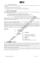
BATTERY (EXTERNAL)
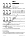
The batteries form the energy reserve to power the load in the absence of the mains power supply to the UPS. They are
housed in dedicated cabinets.
The battery cabinet must be supplied with the electric protection and sectioning
dispositive (automatic breaker or switch with fusibles).
w
w
INVERTER
This represents the output stage and converts the direct voltage from the RECTIFIER or BATTERY into a stabilised
sinusoidal alternating voltage. The inverter output and the load are isolated from the input and battery.
The inverter continually operates and the load connected to the output of the UPS is always supplied by the INVERTER
(in NORMAL OPERATION).
STATIC SWITCH
This device enables the instantaneous automatic or manual switching of the power supply from the protected line
(INVERTER output) to an unprotected line (BY-PASS supply) or vice versa.
Back feed protection is inserted as standard in the SCRs.
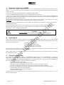
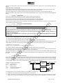
SWMB
Maintenance bypass switch, by closing the SWMB and opening all of the other switches SWIN, SWBY, SWOUT the
UPS is isolated whilst maintaining a supply to the load. This operation is necessary when you have to carry out
maintenance operations inside the equipment, without disrupting the power supplied to the load.
With the SWMB closed and all of the other switches open, there is no voltage inside the equipment (voltages are present
only in the terminal board and in the switches area , N.B. the neutral conductor is not interrupted.)
The manual bypass line is sized for the nominal power of the UPS.
page 16 / 29
0MNMPTM10RUENUA 00