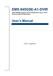
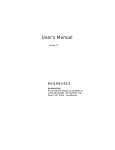
1
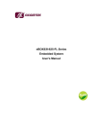
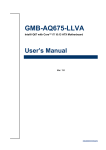
User Manual SIMB-M01 Intel® Atom D525 Mini-ITX Motherboard Safety Information Electrical safety To prevent electrical shock hazard, disconnect the power cable from the electrical outlet before relocating the system. When adding or removing devices to or from the system, ensure that the power cables for the devices are unplugged before the signal cables are connected. If possible, disconnect all power cables from the existing system before you add a device. Before connecting or removing signal cables from the motherboard, ensure that all power cables are unplugged. Seek professional assistance before using an adapter or extension cord. These devices could interrupt the grounding circuit. Make sure that your power supply is set to the correct voltage in your area. If you are not sure about the voltage of the electrical outlet you are using, contact your local power company. If the power supply is broken, do not try to fix it by yourself. Contact a qualified service technician or your retailer. Operation safety Before installing the motherboard and adding devices on it, carefully read all the manuals that came with the package. Before using the product, make sure all cables are correctly connected and the power cables are not damaged. If you detect any damage, contact your dealer immediately. To avoid short circuits, keep paper clips, screws, and staples away from connectors, slots, sockets and circuitry. Avoid dust, humidity, and temperature extremes. Do not place the product in any area where it may become wet. Place the product on a stable surface. If you encounter technical problems with the product, contact a qualified service technician or your retailer. The symbol of the crossed out wheeled bin indicates that the product (electrical and electronic equipment) should not be placed in municipal waste. Check local regulations for disposal of electronic products. SIMB-M01 User Manual Part No. 20060M0101 Edition 2.0 Printed in China November 2011 ii Safety Declaration This device complies with the requirements in Part 15 of the FCC rules. Operation is subject to the following two conditions: This device may not cause harmful interference. This device must accept any interference received, including interference that may cause undesired operation. About this guide This user guide contains the information you need when installing and configuring the motherboard. How this guide is organized This manual contains the following parts: Chapter 1 and 2: Product introduction This chapter describes the features of the motherboard and the new technology it supports. This chapter also lists the hardware setup procedures that you have to perform when installing system components. It includes description of the jumpers and connectors on the motherboard. Chapter 3: BIOS setup This chapter tells how to change system settings through the BIOS Setup menus. Detailed descriptions of the BIOS parameters are also provided. Where to find more information Refer to the following sources for additional information and for product and software updates. Technical Support If a problem arises with your system and no solution can be obtained from the use’s manual, please contact your place of purchase or local distributor. Alternatively, please try the following help resources for further guidance. Visit the Advansus Taiwan website: http://www.advansus.com.tw Optional documentation Your product package may include optional documentation, such as warranty flyers, that may have been added by your dealer. These documents are not part of the standard package. iii SIMB-M01 User Manual Conventions Used in This Guide To make sure that you perform certain tasks properly, take note of the following symbols used throughout this manual. Warning! Information to prevent injury to yourself when trying to complete a task. Caution! CAUTION: Information to prevent damage to the components when trying to complete a task. Important! Instructions that you MUST follow to complete a task. Note! Tips and additional information to help you complete a task. Typography Bold text Indicates a menu or an item to select Italics Used to emphasize a word or a phrase <Key> Keys enclosed in the less-than and greater-than sign means that you must press the enclosed key. Example: <Enter> means that you must press the Enter or Return key If you must press two or more keys simultaneously, the key <Key1>+<Key2>+<Key3> names are linked with a plus sign (+) Example: <Ctrl>+<Alt>+<D> Command SIMB-M01 User Manual Means that you must type the command exactly as shown, then supply the required item or value enclosed in brackets Example: At the DOS prompt, type the command line: afudos /i[filename] afudos /iP5P800VM.ROM iv Packing List Before you begin installing your single board, please make sure that the following materials have been shipped: 1 x Intel D525 mini-ITX Main board 1 x CD ROM per carton, which contains the followings: – User’s Manual in PDF file – Drivers 1 x SATA cable kit (SATA/Power) 1 x I/O Shield 1 x Startup Manual per carton If any of the above items is damaged or missing, please contact your retailer. v SIMB-M01 User Manual SIMB-M01 User Manual vi Contents Chapter 1 Product Overview ................................1 1.1 Specifications Summary............................................................................ 2 1.1.1 System .......................................................................................... 2 1.1.2 Display .......................................................................................... 2 1.1.3 Audio............................................................................................. 2 1.1.4 Ethernet ........................................................................................ 2 1.1.5 I/O ................................................................................................. 2 Block Diagram........................................................................................... 3 Figure 1.1 Block Diagram ............................................................ 3 1.2 Chapter 2 Product Introduction ...........................5 2.1 Product highlights...................................................................................... 6 2.1.1 Product Overview.......................................................................... 6 2.1.2 Platform Features and Benefits .................................................... 6 2.1.3 Key Architecture Features ............................................................ 6 Before you Proceed .................................................................................. 7 Motherboard Overview.............................................................................. 7 2.3.1 Placement Direction...................................................................... 7 2.3.2 Screw Holes.................................................................................. 8 2.3.3 Motherboard Layout...................................................................... 9 Figure 2.1 Motherboard Layout ................................................... 9 2.3.4 Layout Content List ....................................................................... 9 Table 2.1: Slots & socket............................................................. 9 Table 2.2: Jumpers...................................................................... 9 Table 2.3: Rear Panel Connector .............................................. 10 2.3.5 Internal Connector ...................................................................... 10 Table 2.4: Internal Connector .................................................... 10 Central Processing Unit (CPU) ............................................................... 11 2.4.1 CPU location ............................................................................... 11 2.4.2 The CPU Heatsink and Fan ........................................................ 11 System Memory ...................................................................................... 12 2.5.1 Overview ..................................................................................... 12 Table 2.5: 204-Pin DDR3 SODIMM sockets ............................. 12 2.5.2 Memory Configurations............................................................... 13 2.5.3 Installing a DIMM ........................................................................ 13 2.5.4 Removing a DIMM ...................................................................... 14 Expansion Card....................................................................................... 15 2.6.1 Installing an Expansion Card ...................................................... 15 2.6.2 Configuring an Expansion Card .................................................. 15 2.6.3 PCI Express x 1 slot.................................................................... 16 Jumpers .................................................................................................. 17 2.7.1 Clear CMOS (CMOS1) ............................................................... 17 Connectors.............................................................................................. 18 2.8.1 Rear panel connectors................................................................ 18 2.8.2 CPU and System fan connectors (CPU_FAN1,SYS_FAN2) ...... 19 2.8.3 System Panel (F_PANEL) .......................................................... 20 2.8.4 ATX power connectors (ATXPOWER1)...................................... 21 2.8.5 Serial Port connectors ( SERIAL_B) ........................................... 22 2.8.6 Audio Mic.-In & Line-Out Connector (F_AUDIO) ........................ 22 2.8.7 Digital Audio connector (SPDIF_OUT) ....................................... 23 2.8.8 TPM Connector (TPM)................................................................ 24 2.8.9 Serial ATA Connector (SATA0, SATA1) ..................................... 24 2.8.10 USB connectors (F_USB1, F_USB2) ......................................... 25 2.2 2.3 2.4 2.5 2.6 2.7 2.8 vii SIMB-M01 User Manual Chapter 3 BIOS Setup ........................................ 27 3.1 BIOS Setup Program .............................................................................. 28 3.1.1 Legend Box................................................................................. 29 3.1.2 List Box ....................................................................................... 29 3.1.3 Sub-menu ................................................................................... 29 BIOS Menu Screen ................................................................................. 30 Main Setup.............................................................................................. 31 Advanced BIOS Setup ............................................................................ 32 3.4.1 CPU Configuration...................................................................... 33 3.4.2 IDE Configuration ....................................................................... 34 3.4.3 SuperIO configuration................................................................. 36 3.4.4 Hardware Health Configuration .................................................. 37 3.4.5 ACPI Configuration ..................................................................... 38 3.4.6 Power Management Configuration ............................................. 39 3.4.7 PCI Express Configuration ......................................................... 40 3.4.8 Trusted Computing ..................................................................... 41 3.4.9 USB Configuration ...................................................................... 42 PCIPnP ................................................................................................... 43 Boot......................................................................................................... 45 Security ................................................................................................... 46 Chipset.................................................................................................... 47 3.8.1 NorthBridge Chipset Configuration ............................................. 47 3.8.2 South Bridge ............................................................................... 49 Exit .......................................................................................................... 50 3.2 3.3 3.4 3.5 3.6 3.7 3.8 3.9 SIMB-M01 User Manual viii Chapter 1 Product Overview 1 1.1 Specifications Summary 1.1.1 System CPU: Onboard Intel Atom D525 1.8GHz DC Processor BIOS: AMI 8Mb SPI System Chipset: Intel NM10 I/O Chipset: Fintek F71869ED Memory: Two 204-pin SODIMM sockets support up to 4GB single channel DDR3 800MHz SDRAM H/W Status Monitor: Monitoring temperature, voltage and cooling fan status. Auto throttling control when CPU overheats. Expansion Slots: 1 PCI-E x 1 Power State: S1, S3, S4, S5 TPM: Yes, by TPM Header (2 x 10-pin) Wake up on LAN or Ring: LAN (WOL) and Ring (WO) Smart Fan Control: Yes 1.1.2 Display Chipset: Integrated Intel GMA 3150 Display Memory: Shared Memory, up to 224MB Dual Display: VGA + HDMI VGA: Onboard, supports up to 2048 x 1536 (@60Hz) HDMI: Onboard, supports up to 1920 x 1080 1.1.3 Audio Audio Codec: Realtek ALC662, 5.1 Channel HD Audio Audio Interface: Line-in, Line-out, Mic-in, S/PDIF, Front Audio Header 1.1.4 Ethernet LAN: Realtek RTL8111E Gigabit LAN 1.1.5 I/O MIO: 2 COM RS-232 (1 Rear, 1 Internal), 2 SATA II, 1 HDMI, 1 VGA, 1 LAN, 1 LPT, 1 PS/2 Keyboard, 1 PS/2 Mouse USB: 8 USB 2.0 (4 Rear, 4 Internal) * Specifications are subject to change without notice. SIMB-M01 User Manual 2 Chapter 1 1.2 Block Diagram Product Overview Figure 1.1 Block Diagram 3 SIMB-M01 User Manual SIMB-M01 User Manual 4 Chapter 2 2 Product Introduction This chapter describes the motherboard features and the new technologies it supports. 2.1 Product highlights 2.1.1 Product Overview ILNP-IB2 is designed to unleash the power of the new Intel® Atom™ processor D525 which supports the new revolutionary two-chip layout. The Intel® NM10 Express Chipset also provides additional flexibility and upgradeability with two slots of single channel DDR3 memory at 800 MHz supporting up to 4GB maximum. With breakthrough low-power silicon, ILNP-IB2 can be used with a passive thermal solution based on the recommended boundary conditions.1 ILNP-IB2 represents a fundamental shift in system design-small, yet powerful enough to enable a big Internet experience for all audiences. 2.1.2 Platform Features and Benefits ntegrated CHRONTEL CH7036A-BF supports HDMI 1080p resolution and enables excellent graphics performance in power and cost sensitive embedded applications DirectX® 9 let you enjoy awesome graphics performance, stunning 3D visual effect and dynamic interactivity Memory support, integrated low voltage DDR3 memory controller Operating system support: – Microsoft – WindRiver – Redhat – Novell – Green Hills – QNX – LinuxWorks 2.1.3 Key Architecture Features Supports Intel® Atom™ processor D525. – Supports the 800MHz front side bus – 2 Cores, 1MB LLC – Compatible with high speed DDR3-800 – TDP: 16W Intel® HD Audio Technology Intel® HT, EM64T, XD Integrated Display Interfaces – - Dual Independent Display Support – - HDMI – - Analog VGA Doubles the transfer speed of SATA, running at speed up to 3.0Gb/s Provides 10/100 Mbps solution to your network or broadhand connection without having to buy an Onboard 6-channel audio CODEC supports uncompromising DVD audio quality, bringing a move vivid sound experience and high-quality 6-channel audio without having to buy advanced sound cards. USB2.0 is the latest connectivity standard which delivers transfer speeds up to 480Mb/s for easy connectivity and ultra-fast data transfers. SIMB-M01 User Manual 6 I/O – PCI Express® x 1Gen 2 5GT/s – Two SATA ports – 10/100 Mbps Ethernet Media Access Controller – High Definition Audio – USB: Gen 2.0, up to 8 ports – LPT port – Hardware Monitor – Fan control (Voltage, Temp) Chapter 2 Take note of the following precautions before you install motherboard components or change any motherboard settings. Caution! Unplug the power cord from the wall socket before touching any component. Use a grounded wrist strap or touch a safely grounded object or a metal object, such as the power supply case, before handling components to avoid damaging them due to static electricity Hold components by the edges to avoid touching the ICs on them. Whenever you uninstall any component, place it on a grounded antistatic pad or in the bag that came with the component. Before you install or remove any component, ensure that the ATX power supply is switched off or the power cord is detached from the power supply. Failure to do so may cause severe damage to the motherboard, peripherals, and/or components. 2.3 Motherboard Overview Before you install the motherboard, study the configuration of your chassis to ensure that the motherboard fits into it. Refer to the chassis documentation before installing the motherboard. Warning! Make sure to unplug the power cord before installing or removing the motherboard. Failure to do so can cause you physical injury and damage motherboard components. 2.3.1 Placement Direction When installing the motherboard, make sure that you place it into the chassis in the correct orientation. The edge with external ports goes to the rear part of the chassis as indicated in the image below. 7 SIMB-M01 User Manual Product Introduction 2.2 Before you Proceed 2.3.2 Screw Holes Place eight (8) screws into the holes indicated by circles to secure the motherboard to the chassis. Caution! Do not over tighten the screws! Doing so can damage the motherboard. Place this side towards the rear of the chassis. SIMB-M01 User Manual 8 USB+HDMI AUDIO VGA LAN+USB PARALLEL SERIAL_A Chapter 2 2.3.3 Motherboard Layout KB+MS F_AUDIO SPDI/F SYS_FAN1 PCIE_X1_1 TPM F_USB2 D525 F_USB1 SODIMM1 NM10 SODIMM2 CMOS SATA0 SATA1 F_PANEL CPU_FAN1 ATXPOWER Figure 2.1 Motherboard Layout 2.3.4 Layout Content List Table 2.1: Slots & socket Label Label Label Label D525 D525 D525 D525 SODIMM1 SODIMM1 SODIMM1 SODIMM1 SODIMM2 SODIMM2 SODIMM2 SODIMM2 PCIEX1 PCIEX1 PCIEX1 PCIEX1 Table 2.2: Jumpers Label Label Label Label CMOS1 CMOS1 CMOS1 CMOS1 9 SIMB-M01 User Manual Product Introduction SERIAL_B Table 2.3: Rear Panel Connector Label Function Note Page KBMS PS/2 Keyboard and Mouse 6-pin Mini-Din 23 SERIAL_A Serial Connector D-sub 9-pin, male 23 VGA1 VGA Port D-sub 15-pin, female 23 PARALLEL PARALLEL Port HDMI USB12 HDMI Port USB 2.0 Connector x 2 LAN1USB34 RJ-45 Ethernet Connector x 1 USB 2.0 Connector x 2 Audio1 Audio Line-In , Line-Out , Mic.-In 23 HDMI 1.3 19-pin 23 23 5.1 Channel Audio I/O (3 jacks) 23 2.3.5 Internal Connector Table 2.4: Internal Connector Label Function Note Page CPU_FAN1 CPU Fan Connector 3 x 1 wafer, pitch 2.54mm 24 SYS_FAN1 System Fan Connector 4 x 1 wafer, pitch 2.54mm 24 F_PANEL Intel Front Panel connector 5 x 2 header, pitch 2.54mm 24 ATXPOWER ATX power connectors 12 x 2 header 25 SERIAL _B Serial Port Connector 5 x 2 header, pitch 2.54mm 26 F_AUDIO Audio Mic.-In & Line-Out Connec5 x 2 header, pitch 2.54mm tor 26 SPDIF_OUT2 Digital Audio connector 4 x 1 header, pitch 2.54mm 27 TPM TPM Connector 10 x 2 header, pitch 2.54mm 27 SATA Data Connector * 6 7P Male connector 28 USB Connector * 8 5 x 2 header, pitch 2.54mm 28 SATA1 SATA2 USB56 USB78 SIMB-M01 User Manual 10 The motherboard comes with onboard Intel? Atom D525 DC 1.8Ghz Processor. 2.4.1 CPU location 1. Locate the CPU on the motherboard. Chapter 2 2.4 Central Processing Unit (CPU) Product Introduction 2.4.2 The CPU Heatsink and Fan Intel® Atom D525 DC 1.8Ghz Processor requires a specially designed heatsink and fan assembly to ensure optimum thermal condition and performance. CPU_FAN1 CPU FAN 11 SIMB-M01 User Manual Caution! Do not forget to connect the fan cables to the fan connectors. Insufficient air flow inside the system may damage the motherboard components. These are not jumpers! DO NOT place jumper caps on the fan connectors. 2.5 System Memory 2.5.1 Overview The motherboard comes with four 204-pin Double Data Rate 3 (DDR3) SO Dual Inline Memory Modules (DIMM) sockets. A DDR3 module has the same physical dimensions as a DDR SODIMM but has a 204-pin footprint compared to the 204-pin DDR2 SODIMM. DDR3 SODIMMs are notched differently to prevent installation on a DDR2 SODIMM socket. The following figure illustrates the location of the sockets: Table 2.5: 204-Pin DDR3 SODIMM sockets Channel Single Channel SIMB-M01 User Manual Socket SODIMM1 SODIMM2 12 You may install 1 GB and 2 GB unbuffered ECC or non-ECC DDR3 SODIMMs into the SODIMM sockets using the memory configurations in this section. Important! 2.5.3 Installing a DIMM 1. Align a DIMM on the socket such that the notch on the DIMM matches the break on the socket. 2. Firmly insert the DIMM into the socket until the retaining clips snap back in place and the DIMM is properly seated. 13 SIMB-M01 User Manual Product Introduction If you installed two 2GB memory modules, the system may detect less than 3GB of total memory because of address space allocation for other critical functions. This limitation applies to Windows XP 32-bit version operating system since it does not support PAE (Physical Address Extension) mode. IF you install Windows XP 32-bit version operating system, we recommend that you install less than 3GB of total memory. Chapter 2 2.5.2 Memory Configurations Important! A DDR3 SODIMM is keyed with a notch so that it fits in only one direction. DO NOT force a DIMM into a socket to avoid damaging the SODIMM. The DDR3 SODIMM sockets do not support DDR2 SODIMMs. DO NOT install DDR2 SODIMMs to the DDR3 SODIMM socket. Caution! Make sure to unplug the power supply before adding or removing DIMMs or other system components. Failure to do so may cause severe damage to both the motherboard and the components. 2.5.4 Removing a DIMM 1. 2. Simultaneously press the retaining clips downward to unlock the DIMM. Remove the SODIMM from the socket. Note! Support the DIMM lightly with your fingers when pressing the retaining clips. The DIMM might get damaged when it flips out with extra force. SIMB-M01 User Manual 14 In the future, you may need to install expansion cards. The following sub-sections describe the slots and the expansion cards that they support. Warning! Make sure to unplug the power cord before adding or removing expansion cards. Failure to do so may cause you physical injury and damage motherboard components. 1. 2. 3. 4. 5. 6. Before installing the expansion card, read the documentation that came with it and make the necessary hardware settings for the card. Remove the system unit cover (if your motherboard is already installed in a chassis). Remove the bracket opposite the slot that you intend to use. Keep the screw for later use. Align the card connector with the slot and press firmly until the card is completely seated on the slot. Secure the card to the chassis with the screw you removed earlier. Replace the system cover. 2.6.2 Configuring an Expansion Card After installing the expansion card, configure it by adjusting the software settings. 1. Turn on the system and change the necessary BIOS settings, if any. See Chapter 2 for information on BIOS setup. 2. Assign an IRQ to the card if needed. Refer to the tables on the next page. 3. Install the software drivers for the expansion card. 15 SIMB-M01 User Manual Product Introduction 2.6.1 Installing an Expansion Card Chapter 2 2.6 Expansion Card 2.6.3 PCI Express x 1 slot This motherboard supports one PCI Express x 1 slot that complies with the PCI Express specifications. The following figure shows a Capture card installed on the PCI Express x 1 slot. SIMB-M01 User Manual 16 2.7.1 Clear CMOS (CMOS1) Caution! Except when clearing the RTC RAM, never remove the cap on CLRTC jumper default position. Removing the cap will cause system boot failure! Normal (Default) Clear CMOS Note! You do not need to clear the RTC when the system hangs due to overclocking. For system failure due to overclocking, use the C.P.R. (CPU Parameter Recall) feature. Shut down and reboot the system so the BIOS can automatically reset parameter settings to default values. 17 SIMB-M01 User Manual Product Introduction This jumper allows you to clear the Real Time Clock (RTC) RAM in CMOS. You can clear the CMOS memory of date, time, and system setup parameters by erasing the CMOS RTC RAM data. The onboard button cell battery powers the RAM data in CMOS, which includes system setup information such as system passwords. To erase the RTC RAM: 1. Turn OFF the computer and unplug the power cord. 2. Remove the onboard battery. 3. Move the jumper cap from pins 1-2 (default) to pins 2-3. Keep the cap on pins 23 for about 5~10 seconds, then move the cap back to pins 1-2. 4. Re-install the battery. 5. Plug the power cord and turn ON the computer. 6. Hold down the <Del> key during the boot process and enter BIOS setup to reenter data. Chapter 2 2.7 Jumpers 2.8 Connectors 2.8.1 Rear panel connectors 1. 2. 3. 4. 5. 6. 7. 8. PS/2 mouse port (green) This port is for a PS/2 mouse. PS/2 keyboard port (purple) This port is for a PS/2 keyboard. Serial connector This 9-pin COM1 & COM2 port is for serial devices. Parallel Port This is DB-25 parallel printer port. VGA port. This 15-pin VGA port connects to a VGA monitor. USB 2.0 ports 1 ~ 2. These four 4-pin Universal Serial Bus (USB) ports are available for connecting USB 2.0 devices. HDMI port. This 19-pin HDMI 1.3 port connects to a HDMI monitor. LAN (RJ-45) port. This port allows Gigabit connection to a Local Area Network (LAN) through a network hub. Refer to the table below for the LAN port LED indications. LAN port LED indications SPEED LED Status Description ACT/LINK LED Status Description OFF 10 Mbps connection OFF No link Orange 100 Mbps connection Green Link Green 1 Gbps connection Blinking Data activity 9. USB 2.0 ports 1 ~ 4. These four 4-pin Universal Serial Bus (USB) ports are available for connecting USB 2.0 devices. 10. Line In port (light blue). This port connects a tape, CD, DVD player, or other audio sources. 11. Line Out port (lime). This port connects a headphone or a speaker. In 4-channel, 6-channel, and 8-channel configuration, the function of this port becomes Front Speaker Out. 12. Microphone port (pink). This port connects a microphone. SIMB-M01 User Manual 18 The fan connectors support cooling fans of 280mA (3.36 W max.) at 4800rpm or a total of 1A~2.22A (26.64W max.) at +12V. Connect the fan cables to the fan connectors on the motherboard, making sure that the black wire of each cable matches the ground pin of the connector. SYS_FAN1 Systam FAN Caution! Do not forget to connect the fan cables to the fan connectors. Insufficient air flow inside the system may damage the motherboard components. These are not jumpers! DO NOT place jumper caps on the fan connectors. 19 SIMB-M01 User Manual Product Introduction CPU_FAN1 CPU FAN Chapter 2 2.8.2 CPU and System fan connectors (CPU_FAN1,SYS_FAN2) 2.8.3 System Panel (F_PANEL) This connector supports several chassis-mounted functions, for Power Button , Reset button , Power LED , and HDD LED. F_PANEL ATX Power Button/Soft-off Button (Pin 6-8 PWRBT) This 2-pin connector is for the system power button. Pressing the power button turns the system on or puts the system in sleep or soft-off mode depending on the BIOS settings. Pressing the power switch and holding it for more than four seconds while the system is ON turns the system OFF. Reset Button (Pin 5-7 SYS_RST) This 2-pin connector is for the chassis-mounted reset button for system reboot without turning off the system power. Power LED (Pin 2-4 PWR_LED) This 2-pin connector is for the system power LED. Connect the chassis power LED cable to this connector. The system power LED lights up when you turn on the system power, and blinks when the system is in sleep mode. Hard Disk Drive Activity LED (Pin 1-3 HDLED) This 2-pin connector is for the HDD Activity LED. Connect the HDD Activity LED cable to this connector. The IDE LED lights up or flashes when data is read from or written to the HDD. SIMB-M01 User Manual 20 The connector is for ATX power supply plugs. The power supply plugs are designed to fit these connectors in only one orientation. Find the proper orientation and push down firmly until the connectors completely fit. Important! Use of a PSU with a higher power output is recommended when configuring a system with more power-consuming devices. The system may become unstable or may not boot up if the power is inadequate. Make sure that your power supply unit (PSU) can provide at least the minimum power required by your system. See the table below for details. 21 SIMB-M01 User Manual Product Introduction ATXPOWER1 Chapter 2 2.8.4 ATX power connectors (ATXPOWER1) 2.8.5 Serial Port connectors ( SERIAL_B) This connector is for a serial (COM) port. Connect the serial port module cable to this connector, then install the module to a slot opening at the back of the system chassis. SERIAL_B 2.8.6 Audio Mic.-In & Line-Out Connector (F_AUDIO) This connector is for a chassis-mounted front panel audio I/O module that supports either HD Audio or legacy AC’97 (optional) audio standard. Connect one end of the front panel audio I/O module cable to this connector. F_AUDIO SIMB-M01 User Manual 22 2.8.7 Digital Audio connector (SPDIF_OUT) SPDIF_OUT Note! The S/PDIF out module is purchased separately. 23 SIMB-M01 User Manual Product Introduction This connector is for the S/PDIF audio module to allow digital sound output. Connect one end of the S/PDIF audio cable to this connector and the other end to the S/PDIF module. Chapter 2 Important! For motherboards with the optional HD Audio feature, we recommend that you connect a high-definition front panel audio module to this connector to avail of the motherboard's high-definition audio capability. 2.8.8 TPM Connector (TPM) TPM 2.8.9 Serial ATA Connector (SATA0, SATA1) These connectors support SATA 2.0 and are for the Serial ATA signal cables for Serial ATA hard disk drives. SATA0, SATA1 SIMB-M01 User Manual 24 These connectors are for USB 2.0 ports. Connect the optional USB module cable to any of these connectors, then install the module to a slot opening at the back of the system chassis. These USB connectors comply with USB 2.0 specification that supports up to 480 Mbps connection speed. Caution! Never connect a 1394 cable to the USB connectors. Doing so will damage the motherboard! Note! The USB module is purchased separately. 25 SIMB-M01 User Manual Product Introduction F_USB1, F_USB2 USB56, USB78 Chapter 2 2.8.10 USB connectors (F_USB1, F_USB2) SIMB-M01 User Manual 26 Chapter 3 3 BIOS Setup This chapter tells how to change the system setting through the BIOS setup menus. Detailed descriptions of the BIOS parameters are also provided. 3.1 BIOS Setup Program This motherboard supports a programmable firmware chip that you can update using the provided utility. Use the BIOS Setup program when you are installing a motherboard, reconfiguring your system, or prompted to °×Run Setup.°± This section explains how to configure your system using this utility. Even if you are not prompted to use the Setup program, you can change the configuration of your computer in the future. For example, you can enable the security password feature or change the power management settings. This requires you to reconfigure your system using the BIOS Setup program so that the computer can recognize these changes and record them in the CMOS RAM of the firmware hub. The firmware hub on the motherboard stores the Setup utility. When you start up the computer, the system provides you with the opportunity to run this program. Press <Del> during the Power-On-Self-Test (POST) to enter the Setup utility; otherwise, POST continues with its test routines. If you wish to enter Setup after POST, restart the system by pressing <Ctrl+Alt+Delete>, or by pressing the reset button on the system chassis. You can also restart by turning the system off and then back on. Do this last option only if the first two failed. The Setup program is designed to make it as easy to use as possible. Being a menudriven program, it lets you scroll through the various sub-menus and make your selections from the available options using the navigation keys. Important! SIMB-M01 User Manual The default BIOS settings for this motherboard apply for most conditions to ensure optimum performance. If the system becomes unstable after changing any BIOS settings, load the default settings to ensure system compatibility and stability. Select the Load Setup Defaults from the BIOS menu screen. The BIOS setup screens shown in this section are for reference purposes only, and may not exactly match what you see on your screen. Visit the system builder's website to download the latest BIOS file for this motherboard. 28 The keys in the legend bar allow you to navigate through the various setup menus. Function Description ↑↓→← Move Enter Select + / - / PU / PD Value ESC Exit F1 General Help F2 Item Help F5 Previous Value F7 Optimized Defaults F9 Menu in BIOS F10 Save ESC Exit BIOS Setup Key (s) 3.1.2 List Box This box appears only in the opening screen. The box displays an initial list of configurable items in the menu you selected. 3.1.3 Sub-menu Note that a right pointer symbol appears to the left of certain fields. This pointer indicates that you can display a sub-menu from this field. A sub-menu contains additional options for a field parameter. To display a sub-menu, move the highlight to the field and press <Enter>. The sub?menu appears. Use the legend keys to enter values and move from field to field within a sub-menu as you would within a menu. Use the <Esc> key to return to the main menu. Take some time to familiarize yourself with the legend keys and their corresponding functions. Practice navigating through the various menus and submenus. If you accidentally make unwanted changes to any of the fields, press <F6> to load the fail-safe default values. While moving around through the Setup program, note that explanations appear in the Item Specific Help window located to the right of each menu. This window displays the help text for the currently highlighted field. 29 Chapter 3 3.1.1 Legend Box SIMB-M01 User Manual 3.2 BIOS Menu Screen When you enter the BIOS, the following screen appears. The BIOS menu screen displays the items that allow you to make changes to the system configuration. To access the menu items, press the up/down/right/left arrow key on the keyboard until the desired item is highlighted, then press [Enter] to open the specific menu. SIMB-M01 User Manual 30 This menu gives you an overview of the general system specifications. The BIOS automatically detects the items in this menu. Use this menu for basic system configurations, such as time, date etc. Chapter 3 3.3 Main Setup BIOS Setup AMIBIOS Displays the auto-detected BIOS information. Processor Displays the auto-detected CPU specification. System Memory Displays the auto-detected system memory System Time The time format is <Hour>,<Minute>,<Second>. System Date The date format is <Date>,<Month>,<Day>,<Year>. 31 SIMB-M01 User Manual 3.4 Advanced BIOS Setup Select the Advanced tab from the setup screen to enter the Advanced BIOS Setup screen. You can select any of the items in the left frame of the screen, such as Chipset configuration, to go to the sub menu for that item. You can display an Advanced BIOS Setup option by highlighting it using the <Arrow> keys. All Advanced BIOS Setup options are described in this section. The Advanced BIOS Setup screen is shown below. The sub menus are described on the following pages. Caution! Take caution when changing the settings of the Advanced menu items. Incorrect field values can cause the system to malfunction. SIMB-M01 User Manual 32 Chapter 3 3.4.1 CPU Configuration BIOS Setup Max CPUID Value Limit [Disable] Disable for Windos XP. Configuration options: [Disabled] [Enabled] Execute-Disable Bit Capability [Enable] XD can prevent certain classes of malicious buffer overflow attacks when combined with a supporting OS ( Windows Server 2003 SP1, Windows XP SP2, SuSE Linux 9.2 RedHat Enterprise 3 Update 3.) Configuration options: [Disabled] [Enabled] Hyper Threading Technology [Enabled] Enable or disable Hyper-threading support. Configuration options: [Disabled] [Enabled] 33 SIMB-M01 User Manual 3.4.2 IDE Configuration You can use this screen to select options for the IDE Configuration Settings. Use the up and down <Arrow> keys to select an item. Use the <Plus> and <Minus> keys to change the value of the selected option. A description of the selected item appears on the right side of the screen. The settings are described on the following pages. Configure SATA as [IDE] Set the configuration for the Serial ATA connectors supported. Configuration options : [IDE] [AHCI] [Disabled] Setup SATA devices for SATA0 & SATA1 While entering Setup, the BIOS automatically detects the presence of SATA devices. There is a separate sub-menu for each IDE device. Select a device item then press <Enter> to display the SATA device information. The BIOS automatically detects the values opposite the dimmed items (Device, Vendor, Size, LBA Mode, Block Mode, PIO Mode, Async DMA, Ultra DMA, and SMART monitoring). These values are not user-configurable. These items show Not Detected if no SATA device is installed in the system. SIMB-M01 User Manual 34 Chapter 3 BIOS Setup Type [Auto] Select the type of SATA drive. Setting to Auto allows automatic selection of the appropriate SATA device type. Select CD/DVD if you are specifically configuring a CD-ROM/DVD-ROM drive. Select ARMD (ATAPI Removable Media Device) if your device is either a ZIP, LS-120, or MO drive. Configuration options: [Not Installed] [Auto] [CD/DVD] [ARMD] LBA/Large Mode [Auto] Enables or disables the LBA mode. Setting to Auto enables the LBA mode if the device supports this mode, and if the device was not previously formatted with LBA mode disabled. Configuration options: [Disabled] [Auto] Block (Multi-Sector Transfer) [Auto] Enables or disables data multi-sector transfers. When set to Auto, the data transfer from and to the device occurs in multiple sectors at a time if the device supports multi-sector transfer features. When set to [Disabled], the data transfer from and to the device occurs one sector at a time. Configuration options: [Disabled] [Auto] PIO Mode [Auto] Select the PIO mode. Configuration options: [Auto] [0] [1] [2] [3] [4] DMA Mode [Auto] Select the DMA mode. Configuration options: [Auto] [SWDMA0] [SWDMA1] [SWDMA2] [MWDMA0] [MWDMA1] [MWDMA2] [UDMA0] [UDMA1] [UDMA2] [UDMA3] [UDMA4] [UDMA5] [UDMA6]. Only [Auto] is shown if no SATA device is installed in the system. S.M.A.R.T. [Auto] Set the Smart Monitoring, Analysis, and Reporting Technology. Configuration options: [Auto] [Disabled] [Enabled] 32Bit Data Transfer [Enabled] Enables or disables 32-bit data transfer. Configuration options: [Disabled] [Enabled] 35 SIMB-M01 User Manual 3.4.3 SuperIO configuration Serial Port1 Address [3F8/IRQ4] Allows you to select the Serial Port1 base address. Configuration options: [Disabled] [3F8/IRQ4] [3E8/IRQ4] [2E8/IRQ3]. Serial Port2 Address [2F8/IRQ3] Allows you to select the Serial Port2 base address. Configuration options: [Disabled] [2F8/IRQ3] [3E8/IRQ4] [2E8/IRQ3]. Serial Port2 Mode [Normal] Configuration options: [Disabled] [IrDA(1.6us)] [IrDA(3/16 bit)] Parallel Port Address [Disabled] Configuration options: [Disabled] [378] [278] [3BC] SIMB-M01 User Manual 36 You can use this screen for the Hardware Health status. See below. Chapter 3 3.4.4 Hardware Health Configuration BIOS Setup CPU Temperature [xxx°C/xxx°F] The onboard hardware monitor automatically detects and displays the CPU temperature. System Temperature [xxx°C/xxx°F] The onboard hardware monitor automatically detects and displays system temperature. CPU Fan Speed [xxxxRPM] The onboard hardware monitor automatically detects and displays the CPU fan speed in rotations per minute (RPM). If the fan is not connected to the motherboard, the field shows N/A. System Fan Speed [xxxxRPM] The onboard hardware monitor automatically detects and displays system fan speed in rotations per minute (RPM). If the fan is not connected to the motherboard, the field shows N/A. VCC / VSB / VBAT [xxxx Voltage] The onboard hardware monitor automatically detects the voltage output through the onboard voltage regulators. CPU Warning Temperature [Disabled] Set CPU Warning Temperature Configuration options: [Disabled] [60° /140° F] [65° /149° F] [70° /158° F] [75° / 167° F] CPU FAN Mode Setting [Auto Mode] [Manual Mode] Configuration options: [Auto Mode] [Manual Mode] CPU FAN Mode Setting [Manual Mode] Set Fan at fixed Duty-Cycle Configuration options: Min=0, Max=100 37 SIMB-M01 User Manual 3.4.5 ACPI Configuration General ACPI Configuration Suspend Mode [S1 (POS)] Select the ACPI state used for System Suspend. Configuration options: [S1] [S3] . SIMB-M01 User Manual 38 Chapter 3 Chipset ACPI Configuration BIOS Setup High Performace Evant Timer [Enabled] Configuration options: [Enabled] [Disabled] HPET Memory Address [FED0000h] Configuration options: [FED00000h] [FED01000h] [FED02000h] [FED03000h] 3.4.6 Power Management Configuration 39 SIMB-M01 User Manual Restore on AC Power Loss [Last Status] Configuration options: [Last State]. [Power On] [Power Off] USB Device Wakeup From S3 [Disabled] Configuration options: [Disabled] [ Enabled] Resume on Ring [Disabled] Configuration options: [Disabled] [ Enabled] Resume on PCI-E WAKE [Disabled] Configuration options: [Disabled] [ Enabled] Resume on PS2 Keyboard (S3) [Disabled] Configuration options: [Disabled] [ Enabled] Resume on PS2 Mouse (S3) [Disabled] Configuration options: [Disabled] [ Enabled] Resume on RTC Alarm [Disabled] Configuration options: [Disabled] [ Enabled] 3.4.7 PCI Express Configuration Relaxed Ordering [Auto] Configuration options: [Auto] [Disabled] [Enabled] Maxmum Paylosd Size[Auto] Configuration options: [Auto] [128 Bytes] [256 Bytes] [512 Bytes] [1024 Bytes] [2048 Bytes] [4096 Bytes] No Snoop [Auto] Configuration options: [Auto] [Disabled] [Enabled] Maximum Read Request Size [Auto] Configuration options: [Auto] [128 Bytes] [256 Bytes] [512 Bytes] [1024 Bytes] [2048 Bytes] [4096 Bytes] Active State Power Management [Disable] Configuration options: [Disable] Extended Synch [Disables] Configuration options: [Auto] [Disabled] [Enabled] SIMB-M01 User Manual 40 Chapter 3 SB PCI Express Ports Configuration BIOS Setup PCI Express Slot [Auto] Configuration options: [Auto] [Disabled] [Enabled] 3.4.8 Trusted Computing TCG/TPM SUPPORT [No] Displays the information of TCG/TPM SUPPORT 41 SIMB-M01 User Manual 3.4.9 USB Configuration Module version Display USB Module version. USB Devices Enabled. Display the USB connected devices. Legacy USB Support [Enabled] Enables Legacy USB support. AUTO option disables legacy support if no USB devices are connected. DISABLE option will keep USB devices available only for EFI applications. Configuration options: [Enabled] [Disabled][Auto] EHCI Hand-off [Disable] This is a workaround for OSes without EHCI hand-off support. The EHCI ownership change should be claimed by EHCI driver. Configuration options: [Disabled] [Enabled] SIMB-M01 User Manual 42 Chapter 3 3.5 PCIPnP BIOS Setup The PCI PnP menu items allow you to change the advanced settings for PCI/PnP devices. The menu includes setting IRQ and DMA channel resources for either PCI/ PnP or legacy ISA devices, and setting the memory size block for legacy ISA devices. Caution! Take caution when changing the settings of the PCI PnP menu items. Incorrect field values can cause the system to malfunction. Clear NVRAM [No] This item is to clear NVRAM during system boot. Configuration options: [No] [Yes]. Plug and Play O/S [No] When set to [No], BIOS configures all the devices in the system. When set to [Yes] and if you install a Plug and Play operating system, the operating system configures the Plug and Play devices not required for boot. Configuration options: [No] [Yes] PCI Latency Timer [64] Allows the PCI Latency Timer to be adjusted. This option sets the latency of all PCI devices on the PCI bus. Configuration options: [32] [64] [96] [128] [160] [192] [224] [248] 43 SIMB-M01 User Manual Allocate IRQ to PCI VGA [Yes] Set this value to allow or restrict the system from giving the VGA adapter card an interrupt address. Configuration options: [No] [Yes] Palette Snooping [Disabled] Set this value to allow or restrict the system from giving the VGA adapter card an interrupt address. Configuration options: [Disabled] [Enabled] Option Description Disabled This is the default setting and should not be changed unless the VGA card manufacturer requires Palette Snooping to be Enabled. Enabled This setting informs the PCI devices that an ISA based Graphics device is installed in the system. It does this so the ISA based Graphics card will function correctly. This does not necessarily indicate a physical ISA adapter card. The graphics chipset can be mounted on a PCI card. Always check with your adapter card°Øs manual first, before modifying the default settings in the BIOS. PCI IDE BusMaster [Enabled] Set this value to allow or prevent the use of PCI IDE bus-mastering. Configuration options: [Disabled] [Enabled] OffBoard PCI/ISA IDE Card [Auto] Set this value to allow or prevent the use of PCI IDE bus-mastering. Configuration options: [Auto] [PCI Slot1] [PCI Slot2 ] [PCI Slot3 ] [PCI Slot4 ] [PCI Slot5 ] [PCI Slot6 ] IRQ [Available] Set this value to allow the IRQ settings to be modified. Interrupt Option This setting allows the specified IRQ to be used by a PCI/PnP device. This is the default setting. IRQ3 IRQ4 IRQ5 Description Available IRQ7 IRQ9 IRQ10 IRQ11 IRQ14 Reserved This setting allows the specified IRQ to be used by a legacy ISA device. IRQ15 DMA [Available] Set this value to allow the DMA setting to be modified. DMA Channel Option Description Available This setting allows the specified DMA to be used by PCI/PnP device. This is the default setting. Reserved This setting allows the specified DMA to be used by a legacy ISA device. DMA Channel 0 DMA Channel 1 DMA Channel 3 DMA Channel 5 DMA Channel 6 DMA Channel 7 Reserved Memory Size [Disabled] Configuration options: [Disabled] [16K] [32K] [64K] SIMB-M01 User Manual 44 Chapter 3 3.6 Boot BIOS Setup Boot Setting Configuration Quick Boot [Enabled] Configuration options: [Disabled] [Enabled] Quiet Boot [Disabled] Configuration options: [Disable] [Enable] AddOn ROM Display Mode [Force BIOS] Configuration options: [Keep Current] [Force BIOS] 45 SIMB-M01 User Manual Bootup NumLock State [On] Select the keyboard NumLock state Configuration options: [On] [Off] PS/2 Mouse Support [Auto] Configuration options: [Auto] [Disabled] [Enabled] Wait For “F1” If Error [Enabled] Configuration options: [Disabled] [Enabled] Hit “Del” Message Display [Enabled] Configuration options: [Disabled] [Enabled] Interrupt 19 Capture [Disabled] Enabled : Allow option ROMs to trap Int19. Configuration options: [Disabled][Enabled] 3.7 Security Supervisor/User Password The Supervisor/User Password item on top of the screen shows the default Not Installed. After you set a password, this item shows Installed. \ Change Supervisor/User Password (1)Select the Change Supervisor/User Password item and press <Enter> (2)From the password box, type a password composed of at least six letters and/or number, the press <Enter>. Confirm the password when prompted. The message “Password Installed” appears after you successfully set your password. To clear the supervisor/user password, select the change Supervisor/User Password then press <Enter>. The message °×Password Uninstalled°± appears. After you have set a supervisor password, the other items appear to allow you to change other security settings. SIMB-M01 User Manual 46 Boot Sector Virus Protection [Disabled] Configuration options: [Disabled][Enabled] BIOS Setup 3.8 Chipset Chapter 3 Important! If you forget your BIOS password, you can clear it by erasing the CMOS Real Time Clock (RTC) RAM. 3.8.1 NorthBridge Chipset Configuration 47 SIMB-M01 User Manual DRAM Frequency [Auto] Configuration options: [Auto] [Max MHz] Configuration DRAM Timing by SPD [Enabled] Configuration options: [Disabled][Enabled] 3.8.1.1 Video Function Configuration DVMT Mode Select [DVMT Mode] Configuration options: [DVMT Mode][ FIXED Mode] DVMT/FIXED Memory [256MB] Select DVMT/FIXED Mode Memory size used by Internal Graphic Device. Configuration options: [128MB][256MB][Maximum DVMT] Boot Display Device [VBIOS-Default] Configuration options: [VBIOS-Default][CRT][HDMI][CRT+HDMI] SIMB-M01 User Manual 48 Chapter 3 3.8.2 South Bridge BIOS Setup USB Functions [8 USB Ports] Configuration options: [Disabled] [2 USB Ports] [4 USB Ports] [6 USB Ports] [8 USB Ports] USB 2.0 Controller [Disnabled] Configuration options: [Disabled] [Enabled] HDA Controller [Auto] Configuration options: [Auto] [Disabled] LAN Controller [Enable] Enable/Disable LAN1 Controller Configuration options: [Disabled] [Enabled] LAN PXE Boot [Disable] Configuration options: [Disabled] [Enabled] SMBUS Controller [Enable] Configuration options: [Disabled] [Enabled] 49 SIMB-M01 User Manual 3.9 Exit The Exit menu items allow you to load the optimal or failsafe default values for the BIOS items, and save or discard your changes to the BIOS items. Note! Press <ESC> does not immediately exit this menu. Select on of the options from this menu or <F10> from the legend bar to exit. Save Changes and Exit Once you are finished making your selections, choose this option from the Exit menu to ensure the values you selected are saved to the CMOS RAM. An onboard backup battery sustains the CMOS RAM so it stays on even when the PC is turned off. When you select this option, a confirmation window appears. Select [OK] to save change and exit. Discard Changes and Exit Select this option only if you do not want to save the changes that you made to the setup program. If you made changes to fields other than System Date, System time, and Password, the BIOS asks for a confirmation before exiting. Discard Changes This option allows you to discard the selections you made and restore the previously saved values. After selecting this option, a confirmation appears. Select [OK] to discard any changes and load the previously saved values. Load Optimal Defaults This option allows you to load the setup optimal default values for each of the parameters on the Setup menus. When you select this option or if you press <F9>, a confirmation window appears. Select [OK] to load optimal default values. Select [Save Change and Exit] or make other changes before saving the values to the non-volatile RAM. SIMB-M01 User Manual 50 Load Failsafe Defaults This option allows you to load the setup Failsafe default values for each of the parameters on the Setup menus. When you select this option or if you press <F8>, a confirmation window appears. Select [OK] to load optimal default values. Chapter 3 BIOS Setup 51 SIMB-M01 User Manual www.advantech.com Please verify specifications before quoting. This guide is intended for reference purposes only. All product specifications are subject to change without notice. No part of this publication may be reproduced in any form or by any means, electronic, photocopying, recording or otherwise, without prior written permission of the publisher. All brand and product names are trademarks or registered trademarks of their respective companies. © Advantech Co., Ltd. 2011