1
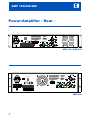
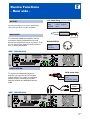
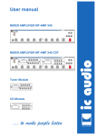
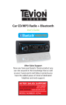
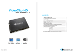
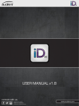
User manual Power Amplifier AMP 120/240/480 AMP 120 POWER AMPLIFIER MUSIC AMP 120 / AMP 240 AMP 480 POWER AMPLIFIER MIC/LINE MUSIC AMP 480 … to make people listen ic audio MIC/LINE Status 02/2006 AMP 120/240/480 ic audio Power-Amplifier - Rear - REMOTE START POWER INPUT:350WATTS MIC/LINE POWER INPUT:350WATTS POWER INPUT:350WATTS SENS MIC LINE AMP 120 / AMP 240 MIC/LINE INPUT POWER INPUT:350WATTS POWER INPUT:350WATTS POWER INPUT:350WATTS REMOTE START SENS MIC LINE MUSIC OUTPUT MUSIC INPUT AMP 480 EN 2 Content Preperation Unpacking 5 Safety Instructions 5 General Informations 5 Rack-Mounting 6 Cooling 6 ic audio Device Functions -Rear side115V und 230V Mains Connections 12 Input Sensitivity 12 24V Battery Connections 13 Remote Start (AMP480) 13 100V/8W Speaker Output 14 Disjoined Anouncement Zones 14 Special Characteristics INPUT 15 Priority INPUT 16 Alarm Function 7 Common Function 7 OUTPUT 17 Top view of all functions 18 Inputs 7 Outputs 7 Devuce Functions -Front side- Further Information Power Amplifiier Settings 20 Cicuit Board Fuse 20 LED - Display 9 Stand alone (default setting )20 ON/OFF -Switch 9 Double - or Treble Operating 20 Volume - Controller 10 Connection Plan 21 Technical Specifications 22 Block Plugging Diagramm 23 Index 24 EN 3 Preparation ic audio Unpacking Please note the unpacking instructions - Unpacking - Safety Instructions - General Informations Safety Instructions Please note the safety instructions before the connecting the AMP 120/240/480 - Rack-Mounting - Cooling General Informations Cooling and instructions for the installation Rack-Mounting Informations about the right rack-mounting Cooling Please note the ventilation - cooling guidelines EN 4 Preparation ic audio General Informations Unpacking Please verify if the following parts were delivered: ! line cord ! mounting foots pre-assembled ! DO NOT run microphone cables near mains, data, telephone or 100V line cables. ! DO NOT run 100V line cables near data, telephone or other low voltage cables. ! DO NOT exceed 90% of the amplifiers output power when using 100V line (speech only). ! DO NOT exceed 70% of the amplifiers output power when using 100V line (high level background music). ! DO NOT use re-entrant horn loudspeakers for background music unless the loudspeaker has been specifically designed for this purpose. ! Safety instructions ! The wires of the main power line have the following colours: GREEN and YELLOW: (E) BLUE: (N) BROWN : (L) ! ! ! AVOID jointing the microphone cable, when this is unavoidable make sure a good screened connector is used, e.g. XLR. ALWAYS use a balanced or floating low impedance microphone terminating into a balanced input on long microphone cable runs. ALWAYS use a mains grade double insulated cable for the loudspeaker cable runs. ENSURE that all loudspeakers are in-phase. ENSURE that there are no short circuits on the loudspeaker line before connecting to the amplifier. As the colours of the wires in the mains lead of this apparatus may not correspond with the coloured markings identifying the terminals in your plug proceed as follows: The wire which is coloured green and yellow must be connected to the terminal which is marked by the letter E or by the safety earth symbol or coloured green and yellow. The wire which is coloured blue must be connected to the terminal which is marked with the letter N or coloured black. The wire which is coloured brown must be connected to the terminal which is marked with the letter L or coloured red. If a 13 Amp (B.S.1363) plug or any other type of plug is used,a 5 Amp fuse must be fitted either in the plug or at the distribution board. 5 EN Preparation ic audio 40°C Rack-Mounting POWER EJECT The housing of the Power Amplifier is a 19 inch rack standard construction. Please check if you have enough space for cooling the amplifier. For the optimum mounting in the 19” rack you should fix the power - amplifier in the rack-frame with 4 screws. Please use for the mounting in the rack-system the support bracket of the rack-producer. Cooling The power amplifier AMP 480 pulls fresh air through the small holes in the front sheet and pushes the exhaust air through the long holes in the rear sheet. The amplifier has a temperature controlled cooling. It will be automatically activated by a increased power consumption. Please make sure that the internal space of the rack system is cooling and you have a room maximum temperature of 40°C.. We recommend to install a cooling system at the rear site of the racksystem to support the transport the exhaust air in the racksystem. EN 6 AUTOREVERSE Background Music Casette Player PROGRAM Exhaust air Special Characteristics ic audio Alarm Function - Alarm Function - Common Function - Inputs ! ! ! 2 split output zones Music muting Priority input Common Function 115V-230V (AMP120/AMP240) Mains Connection ! 230V~240V (AMP480) Mains Connection ! 24V Battery Connection ! - Outputs - Remote Start Inputs ! INPUT RCA Jack Socket XLR 1/4” Stereo Socket Outputs ! ! ! ! 100V Speaker of the first Zone 8 ohm Speaker of the first Zone 100V Speaker of the second Zone OUTPUT RCA Jack Socket XLR 1/4” Stereo Socket Remote Start 7 EN Device Functions - Front side - ic audio LED - Anzeige Display for the activation - LED - Display - ON/OFF - Switch - Controller ON/OFF - Switch Setting - up the Power Amplifier Controller Control of volume - MIC/LINE Control of volume - MUSIC EN 8 Device Functions - Front side - ic audio LED - Display The LED-Display shows the recording level of the Power-Amplifier. The green LEDs show the range in which the AMP 120/240/480 could be operated permanently. The red LED shines only when running in full conduction. This zone is not advisable for long-term usage. LED - Display MIC/LINE MUSIC AMP 120/ 240/ 480 ON/OFF - Switch With this switch you turn on the apparat. After turning the machine on, the LED is shining blue. Before turning the machine on, the Master controller should be set to a low volume. ON/OFF - Switch Power LED MIC/LINE MUSIC AMP 120/ 240/ 480 9 EN Device Functions - Front side - ic audio MIC/LINE & PRIO- Controller With the MIC/LINE or the PRIO-Controller you can change the volume of the Power amplifier. Volume Controller MIC/LINE PRIO AMP 120/ 240/ 480 10 EN Device Functions - Rear side - ic audio 115V~230V Mains Connection AMP 120 AMP 240 Selector to adapt the mains connections - 115V-230V (AMP 120/ AMP 240) Mains Connection - 230V~240V (AMP 480) Main Connection - Input Sensitivity - 24V Battery Supply - Remote Start - 100V/8W Speaker Output 230V~240V Mains Connections AMP 480 Mains Connections Input Sensitivity Adjustment of MIC and LINE Sensitvity 24V Battery Supply Connection to ups Remote Start Switch the Amplifier into operation mode over a distance 100V/8W Speaker Output - INPUT - PRIORITY INPUT - OUTPUT - Top view of all functions Terminal for 100V/8W speakers INPUT Connection to the input sources PRIORITY INPUT Connection to the microphone OUTPUT Connection for priority Top view of all functions Diagramm connected with all possible devices of the power amplifier AMP 120/ 240/ 480 EN 11 Device Functions - Rear side - ic audio 115V ~ 230V (AMP 120/240) 230V~240V (AMP 480) Mains Connection The amplifier is factory set at 230 V(AC) mains voltage. You can set the switch to 115V if neccessary by pushing the slide switch from right to left. A before please disconnect the mains cable. Ensure yourself that the device is set to the local mains voltage before you connect it. Switch 115V-230V AC 115V-230V Mains connection (AMP120 / AMP240) REMOTE START POWER INPUT:350WATTS MIC/LINE POWER INPUT:350WATTS POWER INPUT:350WATTS SENS MIC LINE AMP 120 / AMP 240 AC 230-240V Mains connection (AMP 480) MIC/LINE INPUT POWER INPUT:350WATTS POWER INPUT:350WATTS POWER INPUT:350WATTS REMOTE START SENS MIC LINE MUSIC OUTPUT MUSIC INPUT AMP 480 EN 12 Device Functions - Rear side - ic audio Remote Start 24V-Battery Supply You can also drive the device with 24V(AC). This is useful in case your mains connection is broken down and you can bypass this with an uninteruptible power supply (UPS). In this case no manual switching is interruped at the amplifier. As soon the mains connection, the device is automatically driven by external battery power, regardless to the position of the ON/OFFswitch. Note: The connection cable must be fitted of an inline fuse quick blow type F15A. You can start the amplifier via contact from anywhere. An external power supply (24V) activates the amplifier and bridges the main power switch. 24V-Battery Supply / UPS Connection REMOTE START POWER INPUT:350WATTS MIC/LINE POWER INPUT:350WATTS POWER INPUT:350WATTS SENS MIC LINE AMP 120 / AMP 240 24V-Battery Supply / UPS Connection Remote Start (for external 24V power supply) MIC/LINE INPUT POWER INPUT:350WATTS POWER INPUT:350WATTS POWER INPUT:350WATTS REMOTE START SENS MIC LINE MUSIC OUTPUT MUSIC INPUT AMP 480 EN 13 Device Functions - Rear side - ic audio 100V Speaker Output 8ohm Speaker Output The power amplifier provides two different speaker zones. ! The Music/Speech - Output gives an output at all times reproducing any signal input into the amplifier. ! The Speech Only - Output will only work, when the PRIORITY terminal is connected. POWER INPUT:350WATTS Disjoined Announcement Zones If you want to use the amplifier only temporarily and have the loudspeakerzone muted in normal condition, you can use the SPEECH/ONLY-Output. This output is only working when having contact on the priority terminal. Priority-terminal REMOTE START This output allows connection of standard low impedance speakers. The minimum load impedance must be 8W. When two or more speakers are connected, ensure that they are wired in such a way, that the load impedance is between 8W and 16W. MIC/LINE POWER INPUT:350WATTS POWER INPUT:350WATTS SENS MIC LINE AMP 120 / AMP 240 all the time only when priority MIC/LINE INPUT POWER INPUT:350WATTS POWER INPUT:350WATTS POWER INPUT:350WATTS REMOTE START SENS MIC LINE MUSIC OUTPUT MUSIC INPUT AMP 480 SPEECH ONLY MUSIC / SPEECH Normal EN 14 Priorität Device Functions - Rear side - ic audio 1/4” Jack Plug 6.35 mm Stereo INPUT On the rear side of your amplifier you can connect your particular signal source in the region of input depending on whether it is symmetric or asymmetric. Tip: Ring: Ground: HOT (Signal) COLD (Signal) GND GROUND RING TIP XLR-INPUT BALANCED Use the symmetric input to connect your signal source if it is run by a pre-amplifier or a gear with a similar symmetric guided signal source. 1: SCREEN 2: HOT 3: COLD 2 1 3 AMP 120/240(480) REMOTE START POWER INPUT:350WATTS MIC/LINE POWER INPUT:350WATTS POWER INPUT:350WATTS SENS MIC LINE RCA Jack Plug UNBALANCED There is a rca jack socket for the left and one for the right channel, which are joined together inside the device. HOT (RIGHT) SCREEN (GND) This allows the connection of a stereo gear or a device, that has no symetric output, without any additional special cable. HOT (LEFT) SCREEN (GND) PREAMP CD TUNER TAPE AMP 120/240(480) REMOTE START POWER INPUT:350WATTS MIC/LINE POWER INPUT:350WATTS POWER INPUT:350WATTS SENS MIC LINE 15 Device Functions - Rear side - ic audio 1/4” Jack Plug 6.35 mm Stereo MIC/LINE On the rear side of your amplifier you can connect your microphone or any music source in the plug of MIC/LINE (it is symmetric). The input is adjustable. Tip: Ring: Ground: HOT (Signal) COLD (Signal) GND GROUND RING TIP XLR-INPUT 1: SCREEN 2: HOT 3: COLD 2 1 3 AMP 120/240(480) REMOTE START POWER INPUT:350WATTS MIC/LINE POWER INPUT:350WATTS POWER INPUT:350WATTS SENS MIC LINE EN 16 Device Functions - Rear side - ic audio 1/4” Jack Plug 6.35 mm Stereo OUTPUT By using the output you have the possibility to connect a tape deck or further amplifiers. Tip: Ring: Ground: HOT (Signal) COLD (Signal) GND BALANCED GROUND RING TIP To connect an additional amplifier use the symmetric output provided that your end device has a symmetric input, of course. To do so you can choose either the XLR-socket or the ¼” stereo jack socket. XLR-OUTPUT 1: SCREEN 2: HOT 3: COLD 2 1 3 AMP 120/240(480) REMOTE START POWER INPUT:350WATTS MIC/LINE POWER INPUT:350WATTS POWER INPUT:350WATTS SENS MIC LINE UNBALANCED RCA Jack Plug To connect an asymmetrical power amplifier you can use the RCA socket output at best. The output is conducted double mono to connect your power amplifier without any additional special cable. asymmetr. Input Power Amplifier ( Power Amplifier ) HOT SCREEN (GND) AMP 120/240(480) REMOTE START POWER INPUT:350WATTS MIC/LINE POWER INPUT:350WATTS POWER INPUT:350WATTS SENS MIC LINE EN 17 Device Functions - Rear side - ic audio OVERVIEW of all functions AMP 120 / 240 BALANCED MASTER OUT REMOTE START PRE-Amplifier REMOTE START POWER INPUT:350WATTS UNIT 1 MIC/LINE POWER INPUT:350WATTS POWER INPUT:350WATTS SENS MIC LINE BALANCED IN PUT BOOSTER AMP UNIT 2 OVERVIEW of all functions AMP 480 OVERRIDE BALANCED MASTER OUT REMOTE START PRE-Amplifier UNIT 1 MIC/LINE INPUT POWER INPUT:350WATTS POWER INPUT:350WATTS POWER INPUT:350WATTS REMOTE START SENS MIC LINE MUSIC INPUT MUSIC OUTPUT BALANCED IN PUT BOOSTER AMP EN 18 UNIT 2 Further Information ic audio Power Amplifier Settings Jumper-Settings Circuit Board Fuse - Power Amplifier Settings - Circuit Board Fuse - Stand alone (default setting) Checking the fuse Stand alone (default setting) Jumper-Settings - Double - or Treble Operating Double - or Treble Operating - Connection Plan Jumper-Settings - Technical Specifications - Block Plugging Diagram Connection Plan Overview - Index Technical Specifications Containing all technical specifications Block Plugging Diagram Circut construction Index Content in alphabetical order. EN 19 Further Information ic audio Power amplifier - Settings AMP 120/240/480 SW403 100mV JP1 JP2 500mV SW404 1V print board SW401 Power amplifier-settings The power amplifier have three different input sensitivity settings. You can select the sensitivity with the jumper SW 401. (1V, 500mV und 100mV) Circuit Board Fuse If the amplifier isn’t working, please check the outside fuse on the rear panel or the inside one. SW403 SW404 Stand Alone Master Slave Stand alone (default setting) For the stand alone operation with the power amplifier, select the jumper (SW403 and SW404) of the print board to the “STAND ALONE” Position. EN 20 double - oder treble operating For the double or treble operation define power amplifier as an MASTER - UNIT. Select the jumper to the MASTER position (look at the draft). All further power amplifiers will adjust with the jumper “SLAVE”. (Look at the draft) Further Information ic audio Connection plan AMP 120 (240/480) 120W MX-AMP 120 120W IN AMP 120 100V OUT SW403, 404 Stand Alone com IN AMP 120 SW403, 404 Stand Alone 120W 100V com 120W MX-AMP 120 UNBALANCED OUT 1/4” Stereo Socket, RCA IN AMP 120 OUT SW403, 404 MASTER* IN *Volume control via MASTER unit! 240W AMP 120 100V SW403, 404 SLAVE com EN 21 Further Information ic audio Technical Specifications AMP 120 / 240 Supply Output power Type Model Mains Voltage Battery Voltage Max : Rated : Outputs Inputs Frequency response Total harmonic distortion Signal to noise ratio Controls Indicators AC power consumption DC power consumption Dimensions ( H x W x D ) Weight Color Mounting options TWO ZONE Power Amplifier AMP 120 AC 115V / 230V , 50 / 60HZ ± 10% switchable DC 24V (MAX 10% deviation) 180W 120W Speaker outputs: Music/speech: ohm,100V(70V/100V Selectable) Speech: 100V (70V/100V Selectable) Line output: 1V, 600ohm Line input : 1V, 47K ohm / mic 1mV 250 ohm 50HZ ~ 20KHZ ± 3dB Less than 1% at 1KHZ,rated power. 80dB below rated power. Master volume control. AC 115V / 230V Voltage selector switch. Power indicator (LED),output level indicators (5 LEDS) 400 watts 192 watts 88 x 430 x 300 mm Approx 10.0kg Black Table top or 19” rack mountable. Technical Specification AMP 480 Supply Output power Type Model Mains Voltage Battery Voltage Max : Rated : Outputs Inputs Frequency response Total harmonic distortion Signal to noise ratio Controls Indicators AC power consumption DC power consumption Dimentions ( H x W x D ) Weight Color Mounting options EN 22 TWO ZONE Power Amplifier AMP 480 230V , 50 / 60HZ ± 10% switchable DC 24V (MAX 10% deviation) 720W 480W Speaker outputs: Music/speech: 8ohm,100V(70V/100V Selectable) Speech: 100V (70V/100V Selectable) Line output: 1V, 600ohm Line input : 1V, 47Kohm / mic 1mV 250 ohm 50HZ ~ 20KHZ ± 3dB Less than 1% at 1KHZ,rated power. 80dB below rated power. Master volume control. 230V Voltage selector switch. Power indicator (LED),output level indicators (5 LEDS) 1100 watts 768 watts 88 x 430 x 385 mm Approx 18.0kg Black 19” rack mountable. AMP 240 360W 240W 760 watts 384 watts Approx 13.0kg Further Information ic audio Block Plugging Diagram EN 23 Further Information ic audio INDEX A Alarm Function 7 B Block Plugging Diagram 23 Battery Connection 13 C M Mains Connection 12 Microphone Input 16 O OUTPUT 16 ON/OFF - Switch 9 Cooling 6 Common Function 7 Connection plan 21 P Power amplifier settings 20 G General Information 5 R I Inputs 15 S LED-Display 9 T L Rack-Mounting 6 Safety Instructions 5 Speaker Output 14 Technical Specifications 22 Top view of all functions 18 U Unpacking 5 V Volume - Controller 10 ic audio EN 24 www.ic-audio.com ic audio GmbH Boehringerstraße 14a 68307 Mannheim / Germany Fon:+49(0)621/ 77096-0 Fax:+49(0)621/ 77096-26 www.ic-audio.com Email: [email protected] ic audio … to make people listen