1
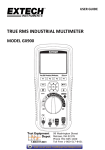
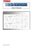
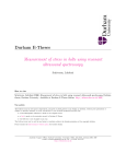
PROGRAMMABLE
UNIVERSAL
SCOPE METER
User’s Manual
S240x_E200707_R01
Programmable
Universal Scope
Contents
1. Easy Manual ............................................................................... 1-1
1.1.
1.2.
1.3.
1.4.
1.5.
1.6.
1.7.
1.8.
1.9.
1.10.
1.11.
1.12.
Turning on and off ................................................................................ 1-1
Division, Trigger and Function key ....................................................... 1-2
Input Terminals .................................................................................... 1-2
Command, Arrow, Backlight & Information key .................................... 1-2
Primary Menu Map .............................................................................. 1-3
Positioning the waveform on the screen .............................................. 1-3
Division key map.................................................................................. 1-4
Changing Vertical (A/div or B/div) division ........................................... 1-4
Changing Horizontal division ............................................................... 1-5
Trigger key map ................................................................................... 1-5
Trigger level control ............................................................................. 1-6
Function key map ................................................................................ 1-6
2. Introduction ................................................................................ 2-1
2.1. Main Features ...................................................................................... 2-1
2.2. Unpacking the Test Tool Kit .................................................................. 2-1
2.3. Specification ........................................................................................ 2-2
2.3.1. General Specifications ........................................................................... 2-2
2.3.2. Technical Specification ........................................................................... 2-3
3. Product Description................................................................... 3-1
3.1. LCD Area ............................................................................................. 3-2
3.2. Keys Area ............................................................................................ 3-3
3.3. Terminal Area ....................................................................................... 3-6
4. Using the METER ....................................................................... 4-1
4.1. Safely Using the Test Tool .................................................................... 4-1
4.1.1.
4.1.2.
4.1.3.
4.1.4.
4.1.5.
4.1.6.
4.1.7.
4.1.8.
Attention ................................................................................................. 4-1
Safety Precautions ................................................................................. 4-1
Powering the METER ............................................................................ 4-1
Changing Backlight ................................................................................ 4-1
Making Selections in a Menu ................................................................. 4-2
Freezing the screen ............................................................................... 4-3
Changing the Graphic Representation................................................... 4-3
Acquiring the Waveform ......................................................................... 4-4
5. Triggering on a Waveform ......................................................... 5-1
5.1.
5.2.
5.3.
5.4.
5.5.
Setting Trigger level (on NORmal trigger mode) .................................. 5-1
Making a single acquisition .................................................................. 5-1
Setting Trigger mode (Tmode) ............................................................. 5-2
Setting AUTO Trigger Level ................................................................. 5-2
Setting Normal Trigger mode ............................................................... 5-3
i
5.6. Setting Trigger Slope ........................................................................... 5-3
6. Storing and Recalling Screens ................................................. 6-1
6.1. Storing Screen ..................................................................................... 6-1
6.2. Recalling Screen.................................................................................. 6-2
7. Remote Interface Operations .................................................... 7-1
7.1. USB HID Device Installation ................................................................ 7-1
7.1.1. System Requirements............................................................................ 7-1
7.1.2. Operating System .................................................................................. 7-1
7.2. Verifying the computer's USB port ....................................................... 7-1
7.2.1. Installing the HID Device........................................................................ 7-1
7.3. To install Windows Application Software .............................................. 7-3
7.4. Running the Application Software ........................................................ 7-4
7.4.1. Oscilloscope Mode ................................................................................ 7-4
8. Maintaining the test tool ............................................................ 8-1
8.1.
8.2.
8.3.
8.4.
8.5.
8.6.
About this Chapter ............................................................................... 8-1
Static Safe Handling ............................................................................ 8-1
Cleaning the Meter .............................................................................. 8-1
Storing the Meter ................................................................................. 8-1
Calibration ........................................................................................... 8-1
Replacing and Disposing of the Li-ION Battery ................................... 8-2
9. Appendices................................................................................. 9-1
9.1. Troubleshooting guide ......................................................................... 9-1
10. Revision History....................................................................... 10-2
10.1. Revised date: Jul. 01, 2007 ............................................................... 10-2
ii
1.
Easy Manual
F4
F3
F2
F1
TRIG
DIV
?
I / O
FUNC
600V
MAX
600V
MAX
600V
MAX
Front View
1.1. Turning on and off
F2
F1
F3
F4
DIV
TRIG
1
?
I / O
FUNC
600V
MAX
600V
MAX
① Pressing this button for 1 to 2 seconds will
turn the unit on.
Pressing this button again will turn the power
off.
600V
MAX
1-1
1.2. Division, Trigger and Function key
F2
F1
1
① Division key:
Adjusts vertical division or Horizontal division.
2
② Trigger key:
Adjusts Trigger level.
Selects Single shot mode.
Selects trigger setup.
F4
F3
DIV
TRIG
?
I / O
3
FUNC
600V
MAX
600V
MAX
③ Function key:
Selects Scope Setup.
Selects general setup.
600V
MAX
1.3. Input Terminals
2
1
I / O
FUNC
600V
MAX
600V
MAX
4
600V
MAX
3
① Channel A:
You can always use the red channel A for all single
input measurements possible with the meter.
② Channel B:
For measurements on two different signals you can
use the channel B together with the Channel A.
③ Common:
You can use the black common as single ground for
low frequency measurements and for ACV, DCV, Ohm,
Continuity measurements.
④ External trigger:
The EXT.TRIG input accepts external trigger signals.
1.4. Command, Arrow, Backlight & Information key
1
2
F2
F1
① Command keys:
These four keys are command buttons.
They are labeled F1-F4. These keys will have various
functions.
F4
F3
TRIG
DIV
?
I / O
② Four arrow keys:
These keys serve as the primary means of navigating
the instrument’s menus and operating displays.
FUNC
③ Display back light:
Press this button to turn on the backlight. To turn the
back light off, press this button again.
600V
MAX
3
600V
MAX
600V
MAX
④ Information key:
General information for the test tool is available.
4
1-2
1.5. Primary Menu Map
Default Menu
Division Menu
Trigger Menu
Function Menu
1.6. Positioning the waveform on the screen
1
2
F2
F1
F4
F3
DIV
3
① Pressing
moves the waveform up.
② Pressing
down.
moves the waveform
③ Pressing
moves the waveform left.
④ Pressing
moves the waveform right.
TRIG
?
I / O
FUNC
4
600V
MAX
600V
MAX
600V
MAX
1-3
1.7. Division key map
1
4
① Pressing
calls up the default
division menu.
F2
F1
2
F4
F3
TRIG
DIV
?
I / O
FUNC
3
600V
MAX
600V
MAX
② Press
to control the Channel B
Vertical Division.
③ Press
Division.
to change the Horizontal
④ Press
to exit.
600V
MAX
1.8. Changing Vertical (A/div or B/div) division
1
F2
F1
① Pressing
button increases CHA
vertical division (A/div).
② Pressing
button decreases CHA
vertical division (A/div).
F4
F3
TRIG
DIV
③ Pressing
or
key will change
Div from MANUAL to AUTO( ).
?
FUNC
I / O
600V
MAX
600V
MAX
600V
MAX
2
3
1-4
1.9. Changing Horizontal division
① Pressing
button increases
Horizontal division (H/div).
1
F2
F1
② Pressing
button decreases
Horizontal division (H/div).
F4
F3
TRIG
DIV
③ Pressing
or
key will change
Div from MANUAL to AUTO( ).
?
FUNC
I / O
600V
MAX
600V
MAX
600V
MAX
2
3
1.10. Trigger key map
4
1
F2
F1
F4
F3
DIV
① Press
key to display the
TRIGGER default menu.
2
TRIG
?
I / O
② Press
mode.
key for Single shot
③ Press
SETUP.
key for TRIGGER
④ Press
to exit.
FUNC
3
600V
MAX
600V
MAX
600V
MAX
1-5
1.11. Trigger level control
Trigger point indicator
Trigger level indicator
1
① Pressing
button
increases the Trigger level.
F2
F1
② Pressing
button
decreases the Trigger level.
F4
F3
DIV
TRIG
?
2
I / O
FUNC
600V
MAX
600V
MAX
600V
MAX
1.12. Function key map
① Press
key to display the
FUNCtion default menu.
1
3
2
1-6
② Press
SETUP.
key for SCOPE
③ Press
SETUP.
key for General
④ Press
to exit.
2.
Introduction
2.1. Main Features
This Programmable Universal Scope Meter offers enhanced features that similar type test
instruments on the market today don't have.
All the functions are designed to be very convenient to use. You can quickly get used to working
with this METER and the great many functions integrated inside. This instrument features:
No
Features
1
PC interface for transferring measurement data and waveform.
2
Dual Channel and Auto Calibration.
3
Automatic setting for horizontal and vertical division.
4
DC to 5MHz(2405), 1MHz(2401) oscilloscope band width
5
Built-in auto ranging True-RMS digital MultiMeter
6
Auto ranging
7
Data hold and run mode.
8
Back light display and Low battery indication.
9
Display Type: Super-Twist 132 x 128 pixels.
10
Designed to comply with safety standard for UL3111, CSA C22.2 No.1010-1
2.2. Unpacking the Test Tool Kit
The following items are included in your test tool kit.
■ STANDARD
#
■ OPTION
Description <Cont.>
# Description <Cont.>
1 Scope Meter <1>
1 Carrying case <1>
2 Li-ion Battery (installed) <1>
2 Holster <1>
3 AC Power & Rechargeable Adaptor <1>
3 PC interface Cable <1>
4 Test Leads <2>
4 Scope Meter Software for Windows <1>
5 CD Users Manual (this book) <1>
Note:
When new, the rechargeable Li-ion Battery is not fully charged.
The accessories may be changed to improve the product quality without notifying the
customers.
2-1
2.3. Specification
2.3.1. General Specifications
1) Operational Temperature:
0°C to +50°C (+32°F to +122°F) at a relative humidity 75% or less
2) Storage Temperature:
-20°C to +60°C with a relative humidity of 75% less
3) Temperature Coefficient:
0.1 x (Specified Accuracy) per °C for temperature <18°C to >28°C
4) Max. Voltage between any Input and Ground: DC or AC 600Vrms
5) Basic DC Accuracy: 0.3%
6) Band width: 5MHz(2405), 1MHz(2401)
7) Meter AC Band width: 20kHz
8) Power Supply: Li-ION Battery 3.7V
9) Battery Life Time:
4 Hours without Backlight on,
3 Hours with Backlight on.
10) Battery Charge Time: About 3 Hours
11) Battery Charge:
Class-2 transformer, Input: 120-240V AC 50/60Hz, Output: 5V DC 1A
12) Display Type: Super-Twist 132 x 128 pixels
13) Equipment Dimensions:
90 mm (width) x 195 mm (depth) x 40 mm (height)
14) Equipment Weight: 1.0 lbs. (480g) approx. without Holster
2-2
2.3.2. Technical Specification
1) Oscilloscope Function
(1) Horizontal
Sample Rate
50 MS/s (Single CH mode), 25 MS/s (Dual CH mode)
Record Length
512 single shot mode, 256 in all modes
Sample / Division
25
Modes
Single shot, Roll, Normal
Accuracy
0.01%
Sweep Rate
1uS to 5S in 1, 2, 5 sequence
(2) Vertical
Bandwidth
S2401: 1MHz, S2405: 5MHz
Resolution
8 Bit
Channels
Dual
Coupling
AC, DC
Input impedance
1 MΩ
Accuracy
3%±1Pixel
Max. Input Volts
DC or AC 600Vrms
S2401
0.5 V to 500V in 1, 2, 5 sequence
S2405
50 mV to 500V in 1, 2, 5 sequence
Volt / Division
(3) Triggering
Type
CHA, CHB, External
Coupling
AC, DC
Slope
Rising (↑) or Falling (↓) edge
Internal Trigger Sensitivity
2 / 20 Division
(4) Waveform Memory
Waveform Memory
16 Shots
2-3
2) Digital MultiMeter Function
DC V
Model
Scope V/Div
S2405
50m, 0.1, 0.2
S2401
S2405
DMM Range
Resol.
Accuracy
500mV
0.1mV
0.5, 1, 2
5V
0.001V
5, 10, 20
50V
0.01V
50, 100, 200
500V
0.1V
500
1000V
0.1V
Imped.
±(0.3%+3)
1 MΩ
±(0.5%+5)
AC V
Model
Scope
V/Div
S2405
50m, 0.1, 0.2
S2401
S2405
DMM
Range
Resol.
Accuracy (Hz)
50~450
0.45k~5k
5k~20k
±(0.75%
+5)
±(2%+5)
±(3.5%
+5)
±(2.5%+5)
N/A
300mV
0.1mV
0.5, 1, 2
3V
0.001V
5, 10, 20
30V
0.01V
50, 100, 200
300V
0.1V
500
750V
0.1V ±(1.2%+5)
Imped.
1 MΩ
The Voltage for more than 200V in Frequency range 5kHz to 20kHz: Not Specification
OHM
Scope
Div
DMM Range
Resolution
1 kΩ
5 kΩ
0.001 kΩ
10 kΩ
50 kΩ
0.01 kΩ
100 kΩ
500 kΩ
0.1 kΩ
5 MΩ
0.001 MΩ
1 MΩ
Over Load
Protection
Accuracy
±(0.5%+5)
600V DC or
AC rms
±(0.75%+10)
Continuity Buzzer
Test Voltage
Threshold
Over Load Protection
1.7V
100 digits
600V DC or AC rms
2-4
Frequency
Range
Resolution
100 Hz
0.01 Hz
1 kHz
0.0001 kHz
10 kHz
0.001kHz
100 kHz
0.01kHz
1 MHz
0.0001MHz
10 MHz (2405)
0.001MHz
Accuracy
Overload protection
±(0.05%+5)
600V DC
or AC rms
The guaranteed range is below 5 MHz.
RPM
Range
Resolution
Accuracy
240 - 60,000
1 RPM
±(0.05%+5)
Pulse Width
Range
2uS-500mS (Pulse Width > 2uS)
% Duty
Range
25% - 75%
2-5
3.
Product Description
In this chapter, the LCD, front panel buttons, controls and terminal are described.
F2
F1
F4
F3
TRIG
DIV
?
I / O
FUNC
600V
MAX
600V
MAX
[Front View]
3-1
600V
MAX
3.1. LCD Area
The screen is divided into five areas: Indicator area, Reading area, Waveform area, Setting area
and Menu area. Refer to Figure below.
[LCD Display]
1) Indicator
▪ HOLD: Freezes display in the LCD
▪ REMOTE: USB Output indicator
▪ BACK LIGHT( ): Back light indicator
▪ BUZZER( ): Buzzer indicator
▪ Charging LINE( ): Charging Battery indicator
▪ BATTERY( ): Low battery indicator
2) Primary Numerical Field (DMM Function)
Displays the numerical readings. Because only input A is on, you will see the input A readings
only.
3) Trigger selection
▪ Channel A, B and External
3-1) Trigger level indicator
3-2) Trigger Cursor
4) Trigger Slope
▪ Rising or Falling edge
5) Trigger mode: Normal or AUTO
6) Channel mode status
Vertical mode: ▪ CHA ▪ CHB ▪ A&B
Horizontal mode:
▪ Normal ▪ Roll
7) Memory Address
▪ 0 to 15
3-2
8) Live Scope Display (Channel A)
Displays real time waveforms and freezes held captures.
9) Channel B
10) Channel A Vertical Division
11) Channel B Vertical Division
12) Horizontal Division (Time base)
13) Command Menu Field
3.2. Keys Area
F2
F1
F3
DIV
F4
TRIG
?
I / O
FUNC
[Keys Area]
14)
Command Menu keys
All Keys are command buttons. They are labeled F1~F4. These keys will have various functions.
①
Default (Command Menu)
A
B
Mem
3-3
Hold
15)
Arrow keys
Use the black arrow keys to highlight the item.
①
The cursor to be changed is moved to up with this button. Pushing the
button will increase the value or position.
②
The cursor to be changed is moved to down with this button. Pushing
the button will decrease the value or position.
The cursor to be changed is moved to left with this button.
Pressing this button changes Vertical division or horizontal division
from MANUAL to AUTO.
The cursor to be changed is moved to right with this button.
Pressing this button changes Vertical division or horizontal division
from MANUAL to AUTO.
③
④
16)
Division key
Set Channel A, B and Horizontal Division
①
DIV
A/div
17)
B/div
H/div
Exit
Singl
Tmode
Exit
Trigger key
Set Trigger level, Single mode and Setup
①
TRIG
Tlvl
②
F3
TRIGGER SETUP
SOURCE:
■ CHA □
CHB
□ EXT
SLOPE:
□
■
TRIGGER MODE:
□ AUTO
■ NOR
Set
3-4
Exit
18)
Back light key
Activates Back Light for the LCD
Toggles backlight ON and OFF.
19)
Information key
Provides meter model number, firmware version, serial number, calibration date and
manufacture date
20)
Power switch
Turns the instrument ON or OFF.
21)
Function Key
Set Scope, Auto Scope and Setup of the METER
①
FUNC
Scope
SetUp
Exit
▪ Scope Setup
①
FUNCÎF1 (Scope)
SCOPE SETUP
INPUT A:
INPUT B:
■ DC
□ AC
■ DC
□ AC
VERTICAL MODE:
□ CHA
□ CHB
□ A&B
HORIZONTAL MODE:
■ NORM
□ ROLL
MEASUREMENTS A:
■ DCV □ ACV
□ OHM
□ BZ
□ HZ
□ RPM □ P/W
□ DTY
Set
3-5
Exit
3.3. Terminal Area
600V
MAX
600V
MAX
600V
MAX
[Terminal Area]
22) Terminals description
Look at the bottom of the METER. The METER provides 4 input jacks.
① CHA: Channel A
You can always use the red channel A for all single input measurements possible with the Meter.
② COM: Common
You can use the black COMMON as single ground for DCV, ACV, Ohm, Continuity, frequency
and RPM measurements.
③ CHB: Channel B
For measurements on two different signals you can use the channel B together with the red
channel A.
④ EXT. TRIG
External trigger.
3-6
4.
Using the METER
4.1. Safely Using the Test Tool
4.1.1. Attention
Carefully read the following safety information before using the test tool.
4.1.2. Safety Precautions
Specific warning and caution statements, where they apply, will be found throughout the manual.
A Caution identifies conditions and actions that may damage the test tool. A Warning identifies
conditions and actions that pose hazard(s) to the user.
Symbols used on the test tool and in this manual are explained in the next table.
Warning
To avoid electrical shock, use only specific power supply, Model (Power Adapter used as a Battery Charger).
See explanation in manual
Dangerous Voltage
Double Insulation (Protection Class)
Earth (Ground)
Either AC or DC
DC – Direct Current
AC – Alternating Current
Fuse
4.1.3. Powering the METER
Follow the procedure to power the Meter from a standard ac outlet.
①
Power Adaptor is inserted in to AC outlet.
②
Power AdaptorÎ the Meter.
③
Turn the Meter on by pressing this button for about 3 seconds.
The meter powers up in its last setup configurations.
4.1.4. Changing Backlight
After power-up, the screen has a high bright display.
To save battery power, the screen has an economic brightness display when operated on the
battery pack (no power adapter connected).
To change the brightness of the display, do the following:
①
Brighten the backlight.
②
Dim the backlight again.
The high brightness increases when you connect the power adapter.
Note
Using dimmed display lengthens maximum battery power operation time by about one hour.
4-1
4.1.5. Making Selections in a Menu
Subsequently follow steps ① to ⑤ to open a menu and to choose an item.
Open the FUNCTION menu.
Scope
SetUp
①
Exit
Open the Scope Setup menu.
SCOPE SETUP
INPUT A:
INPUT B:
■ DC
□ AC
■ DC
□ AC
VERTICAL MODE:
□ CHA
□ CHB
■ A&B
HORIZONTAL MODE:
■ NORM
□ ROLL
MEASUREMENTS A:
■ DCV □ ACV
□ OHM
□ BZ
□ HZ
□ RPM
□ P/W
□ DTY
②
Set
③
Use the arrow keys to highlight the item.
④
Select the proper item.
⑤
Exit.
Key:
Î
Î
Î
Exit
Î
1) To choose a Frequency measurement for CHA, do the following:
①
Plug the black test lead into the COM input jack.
②
Plug the red test lead into the CHA input jack.
③
Open the FUNCTION menu.
Scope
SetUp
④
Exit
Open the Scope Setup menu.
SCOPE SETUP
INPUT A:
INPUT B:
■ DC
□ AC
■ DC
□ AC
VERTICAL MODE:
□ CHA
□ CHB
□ A&B
HORIZONTAL MODE:
■ NORM
□ ROLL
MEASUREMENTS A:
■ DCV
□ ACV
□ OHM
□ BZ
□ HZ
□ RPM
□ P/W
□ DTY
Set
⑤
Highlight Hz (□ Hz )
⑥
Select Hz (■ Hz )
⑦
Exit.
4-2
Exit
Key:
Î
Î
Î
Î
Observe that Hz is now the main reading.
4.1.6. Freezing the screen
You can freeze the screen (all readings and waveforms) at any time.
Default (Command Menu) Display:
A
B
Mem
Hold
①
Freeze the screen. Highlighted Hold appears at the bottom of the
Command Menu area.
A
B
Mem
Hold
②
Resume your measurement
A
B
Mem
Hold
H/div
Exit
4.1.7. Changing the Graphic Representation
1) Changing the vertical division
Open the Command Menu.
A/div
B/div
①
②
or
③
④
⑤
or
Change the vertical division. (CH A or CH B)
Increase the vertical division
Div is changed to manual mode.
Decrease the vertical division.
Div is changed to manual mode.
Change Div from Manual mode to AUTO mode.
2) Changing the Time Base
①
Open the Command Menu.
A/div
B/div
H/div
Exit
②
Change the Horizontal division.
A/div
B/div
H/div
Exit
Increase the number of periods.
Div is changed to manual mode.
Decrease the number of periods.
Div is changed to manual mode.
③
④
⑤
or
Change Div from Manual mode to AUTO mode.
4-3
4.1.8. Acquiring the Waveform
①
②
Open the FUNCTION menu.
Scope
SetUp
Exit
Open the Scope Setup menu.
SCOPE SETUP
INPUT A:
INPUT B:
■ DC
□ AC
■ DC
□ AC
VERTICAL MODE:
□ CHA
□ CHB
□ A&B
HORIZONTAL MODE:
■ NORM
□ ROLL
MEASUREMENTS A:
■ DCV
□ ACV
□ OHM
□ BZ
□ HZ
□ RPM
□ P/W
□ DTY
Set
Exit
Recording Slow Signals over a Long Period of Time
③
Highlight ROLL MODE.
④
Set ROLL MODE.
⑤
Exit.
Key:
Î
Î
Î
Î
The roll mode function supplies a visual log of waveform activity and is especially useful when you
measure lower frequency waveforms.
Note
ROLL MODE operates when the horizontal division is between 1s and 5s
Selecting AC-Coupling for INPUT A
③
Highlight AC for INPUT A.
④
Accept AC-coupling for INPUT A.
⑤
Exit.
Key:
Î
Î
Î
Î
Use AC-coupling when you wish to observe a small AC signal that rides on a DC signal.
4-4
5.
Triggering on a Waveform
Triggering tells the METER when to begin displaying the waveform. You can select which input
signal should be used, on which edge this should occur and you can define the condition for a new
update of the waveform.
The right-top line of the LCD identifies the trigger parameters being used. Trigger icons on the
screen indicate the trigger level and slope.
(1) Trigger Channel: Channel A or B
(2) Slope: rising or falling
(3) Trigger mode: Trigger setting mode (Auto or
Normal)
(4) Trigger Level indicator
(5) Trigger Cursor
(6) Command Menu: Trigger level
(7) Command Menu: Single shot
(8) Command Menu: Trigger mode (Setup)
Screen with all Trigger Information
5.1. Setting Trigger level (on NORmal trigger mode)
①
Open the Trigger menu
Tlvl
③
Adjust the Trigger Level continuously. Observe the trigger icon on the
second time division line indicates the trigger level.
③
Exit.
Key:
Î
Singl
Tmode
Exit
Î
5.2. Making a single acquisition
To catch single events, you can perform a single shot. (One time screen update.) To set up the test
tool for a single shot on the input A waveform, do following:
* Connect the probe to the signal to be measured.
Open the default Trigger menu
①
Singl
Tmode
Exit
Tlvl
Highlight Singl (SINGLE SHOT)
②
Singl
Tmode
Exit
Tlvl
Test tool performs a single shot. (One time screen update)
Return to normal Trigger mode.
Singl
Tlvl
③
Key:
Î
Î
5-1
Tmode
Exit
5.3. Setting Trigger mode (Tmode)
Open the Trigger menu
Tlvl
①
Singl
Tmode
Exit
Open the Trigger Setup
TRIGGER SETUP
SOURCE:
■ CHA □
CHB
□ EXT
②
TRIGGER MODE:
□ AUTO
SLOPE:
□
■
■ NOR
Set
③
Highlight the ITEM you want.
④
Set the ITEM.
⑤
Exit.
Key:
Î
Î
Î
Exit
Î
5.4. Setting AUTO Trigger Level
For quick operation, use the AUTO trigger mode to trigger on nearly all signals automatically. To
optimize trigger slope manually, do the following:
Open the Trigger menu
Tlvl
①
Singl
Tmode
Exit
Open the Trigger Setup
TRIGGER SETUP
SLOPE:
SOURCE:
■ CHA □ CHB
□
□ EXT
■
②
TRIGGER MODE:
□ AUTO
■ NOR
Set
③
Highlight AUTO.
④
Set AUTO.
⑤
Exit.
Key:
Î
Î
Î
Î
5-2
Exit
5.5. Setting Normal Trigger mode
Highlight NOR.
④
Set NOR.
⑤
Exit.
Adjust the Trigger Level continuously. Observe the trigger icon on the
second time division line indicates the trigger level.
Key:
Î
Î
Î
Î
5.6. Setting Trigger Slope
③
Highlight
④
Set
⑤
Exit.
or
Key:
Î
or
or
.
.
.
Trigger on either positive Slope or negative Slope of the chosen
waveform.
Î
Î
Î
5-3
6.
Storing and Recalling Screens
The meter can store setups and waveforms to memory for later recall. Sixteen (0-15) setup and
waveform memories are available.
6.1. Storing Screen
To store a screen, do the following:
①
②
Default
Open the memory (Mem) menu
Sto
Rcl
R/wfm
Exit
Memory field (M;0) appears at the top-right corner of the display area.
③
Select the memory address you want to store in.
④
Store the actual screen
6-1
6.2. Recalling Screen
To recall a screen, do the following:
①
②
Default
Open the memory menu
Sto
Rcl
R/wfm
Exit
Memory field (M;0) appears at the top-right corner of the display area.
③
Select the memory address you want to recall from.
④
View the saved screen.
The image is presented as a picture that can no longer be changed.
6-2
7.
Remote Interface Operations
This section explains how to install the USB device driver.
If you have any questions after reading this information, please contact your local service
representative.
Remote Interface is Optional.
7.1. USB HID Device Installation
7.1.1. System Requirements
Desktop or Laptop computer with:
1) The IBM PC or Compatible Computer.
2) The Windows operating system: Refer to the Readme file in CD-ROM.
3) The CD-ROM Drive
4) USB Port for Connection with Instrument
This is restricted to devices that have USB ports and for which the manufacturer of the computer
guarantees the operation of the USB port.
7.1.2. Operating System
z Microsoft Windows 2K/XP/2K3 or above
7.2. Verifying the computer's USB port
1) Ensure that the USB HandyScope is plugged in.
2) Pressing I/O key for 1 to 2 seconds will turn the unit on.
3) Right click on the My Computer icon and open [Properties].
4) Select the [Hardware] tab and click the [Device Manager] button to open [Device Manager].
5) Check that [Human Interface Device] is displayed.
* If [Human Interface Device] is not displayed, the USB device driver cannot be used.
7.2.1. Installing the HID Device
1) Plug in the 4 Pin type into the USB port on the Meter, and connect the USB connector type on
the other end of the cable to the host USB port in your PC.
2) Pressing I/O key for 1 to 2 seconds will turn the unit on.
3) The Windows operating system displays "Found New Hardware" and automatically installs the
Human Interface Device (HID) driver. HIDs do not require a custom USB driver. Support for
HIDs is built into Windows.
4) Review the status of the HID using the Device Manager.
5) Right click on My Computer to open the System Properties - Hardware dialog. Then click on
Device Manager.
7-1
[Figure 1: System Properties]
6) Right click on the Human Interface Device to open the Properties dialog which contains the
description and status of the HID device.
[Figure 2: Device Manager]
7-2
7.3. To install Windows Application Software
1) Insert the HandyScope software installation guide CD into the CD-ROM drive of your PC.
2) Open Windows® Explorer and double-click the CD-Rome drive.
3) Auto Run or Windows users can simply double click on Setup.exe’.
[Step 1: Choose Setup Language]
[Step 2: Preparing to Install]
[Step 3: Welcome to the… HandyScope]
[Step 4: Ready to Install the Program]
[Step 5: Installing HandyScope]
[Step 6: Installed Wizard Completed]
7-3
7.4. Running the Application Software
1) For using USB port your PC should have USB port. Connect USB cable to HandyScope at one
end and to PC at other end.
2) Turn the HandyScope on.
3) Click [StartÆProgramsÆHandyScopeÆHandyScope]
The HandyScope window will pop up as below
7.4.1. Oscilloscope Mode
1) Click the [LINK] Button and the [Start] Button.
1
2
3
①LINK Button, ②Screen Print, ③ Start / Stop Button for Oscilloscope
7-4
Display Area
1
2
① Sampling Time (0.001 to 9999)
3
② Trigger level indicator (-T)
③ Trigger point indicator (T)
Control Panel Area
④ Channel A (Vertical Position, Division,
6
Auto, ON/Off and DC coupling)
5
⑤ Channel B (Vertical Position, Division,
4
Auto, ON/Off and DC coupling)
⑥ Horizontal Division and Trigger
7
(Horizontal Division, Auto, Trigger Level,
8
Source and Position)
⑦ Measurement Function (DCV, ACV, OHM, BZ,
Hz, RPM, Pulse Width and Duty)
9
⑧ Recalling Screens from Memory
⑨ Storing and Recalling Screens from PC
Data
7-5
8.
Maintaining the test tool
Warning!
z This section is very important for safety. Read and understand the following instruction fully
and maintain your instrument properly.
z The instrument must be calibrated and inspected at least once a year to maintain the safety
and accuracy.
8.1. About this Chapter
This chapter covers basic maintenance procedures that can be performed by the user and
provides handling, cleaning, battery replacement, disassembly, and assembly instructions.
8.2. Static Safe Handling
Observe the following rules for handling static-sensitive devices:
1. Handle all static-sensitive components at a static-safe work area.
Use grounded static control table mats on all repair meters, and always wear a grounded wrist
strap. Handle boards by their nonconductive edges only. Store plastic, vinyl, and Styrofoam
objects outside the work area.
2. Store and transport all static-sensitive components and assemblies in static shielding bags or
containers. Static shielding bags and containers protect components and assemblies from
direct static discharge and external static fields. Store components in their original packages
until they are ready for use.
8.3. Cleaning the Meter
Warning!
To avoid electrical shock or damage to the meter, never allow water inside the case. To avoid
damaging the meter’s housing, never apply solvents to the meter.
If the meter requires cleaning, wipe it down with a cloth that is lightly dampened with water or a
mild detergent. Do not use aromatic hydrocarbons, chlorinated solvents, or methanol-based fluids
when wiping the meter.
8.4. Storing the Meter
If you are storing the Meter for an extended period of time, charge the LI-ION battery pack before
storing. It is not necessary to remove the battery pack.
8.5. Calibration
The manufacturer may conduct the calibration and inspection. For more information, please
contact the manufacturer.
8-1
8.6. Replacing and Disposing of the Li-ION Battery
Warning!
To avoid electrical shock, remove the test leads and probes before replacing the battery pack.
Caution
Handle the PCB Assembly by its edges or while wearing gloves; avoid contaminating the PCB
Assembly with oil from tour fingers.
A contaminated PCB Assembly may not cause immediate instrument failure in controlled
environments. Failures typically show up when contaminated units are operated in humid areas.
Note
This instrument contains a LI-ION battery pack. Do not dispose of this battery pack with other solid
waste. Used batteries should be disposed of by a qualified recycler or hazardous materials handler.
To replace the battery pack
1. Remove the Meter Case
3 PCS
Use the following procedure to remove the
meter case.
① Release the test leads
Disconnect the test leads and probes both
at the source and at the meter.
② Power OFF
Make sure the meter is turned off and
unplugged from the power Adaptor.
③ Remove Screw:
Remove the three screw from the bottom of
the case. (3 pcs)
④ Remove the PCB Assembly:
Now remove the PCB Assembly by
releasing the four snap retainers securing it
to the case.
S1
2. Remove Rubber key and Battery Pack
Rotate the PCB Assembly 180 degrees.
① Remove Rubber Key:
② Remove Battery Pack:
Remove the battery plug from the
connector.
3. Install a new battery pack.
4. Reinstall the rear cover and secure the screws.
8-2
9.
Appendices
9.1. Troubleshooting guide
If you experience trouble with your instrument, try these corrective actions before concluding that
the instrument needs repair.
1. Make sure you are using fresh Li-ion battery or fully charged rechargeable battery pack. If you
are using the AC/DC power adapter, make sure the adapter is plugged into an appropriate live
power source.
2. If the buttons do not respond to your control or the contrast is set such that the display is
unreadable, remove the power source while the instrument is on. Wait 15 minutes and then
restore power and try operations.
3. If you still experience difficulty, check your connections and reread the usage instructions.
4. If meter is frozen while you control the trigger level:
If you set the trigger level to normal (NOR) mode, trigger level must be the same level of
waveform. Meter does not trigger if trigger level set above or below waveform.
If you set the trigger level to Auto (AT) mode, you do not need to control the trigger level.
In rare cases, your instrument may require servicing. There are no user-serviceable parts inside
the instrument. For service, return the instrument to your customer service center.
9-1
MEMO
Mouser Electronics
Authorized Distributor
Click to View Pricing, Inventory, Delivery & Lifecycle Information:
Protek:
S2401U