1
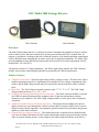
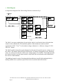
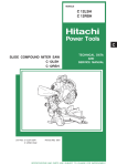
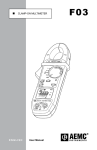
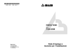
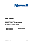
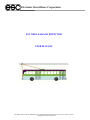
Electronic Surveillance Corporation
ESC 3800 LEAKAGE DETECTOR
USER MANUAL
90 Nolan Court, Unit 34, Markham, ON, Canada, L3R 4L9 Tel: 905-479-7116 Fax: 905-477-2826
[email protected]
Table of Contents
TABLE OF CONTENTS ...................................................................................................................................................1
DESCRIPTION ..................................................................................................................................................................2
ENHANCED FEATURES .................................................................................................................................................2
STANDARD FEATURES..................................................................................................................................................3
BLOCK DIAGRAM...........................................................................................................................................................4
THEORY OF OPERATION .............................................................................................................................................5
LEAKAGE PATH ..............................................................................................................................................................5
INSULATION CHARATERISTICS .......................................................................................................................................6
SENSITIVITY ...................................................................................................................................................................7
INSTALLER'S TEST/CALIBRATION ...................................................................................................................................8
INSTALLATION INSTRUCTIONS ................................................................................................................................9
3800-1 HIGH VOLTAGE MODULE ...................................................................................................................................9
FUSING ...........................................................................................................................................................................9
FUSE RATING ...............................................................................................................................................................10
3800-2 DETECTOR MODULE.........................................................................................................................................11
DRIVER’S CONSOLE/DASHBOARD ................................................................................................................................11
WIRING DIAGRAMS .....................................................................................................................................................12
OPERATION ....................................................................................................................................................................14
3800-2 MODULE ..........................................................................................................................................................14
ADAPTIVE THRESHOLD TRIP LEVEL .............................................................................................................................15
TEST SWITCHES/REMOTE INPUTS .................................................................................................................................15
DASHBOARD CONTROLS...............................................................................................................................................15
SERVICING......................................................................................................................................................................15
OPERATIONAL TESTING ................................................................................................................................................15
ISOLATION TESTING .....................................................................................................................................................15
REPAIR .........................................................................................................................................................................16
BENCH TESTING ...........................................................................................................................................................16
WARRANTY ....................................................................................................................................................................16
SPECIFICATIONS ..........................................................................................................................................................17
ELECTRICAL/OPERATIONAL .........................................................................................................................................17
MECHANICAL/ENVIRONMENTAL ..................................................................................................................................17
Documentation Rev. 4.1
90 Nolan Court, Unit 34, Markham, ON, Canada, L3R 4L9 Tel: 905-479-7116 Fax: 905-477-2826
[email protected]
Page 1
ESC Model 3800 Leakage Detector
3800-1 Module
3800-2 Module
Description
The model 3800 leakage detector is a safety device that is intended to be installed in electric vehicles
such as trolley busses, that run on rubber tires, and are powered from 600VDC overhead lines. Its
purpose is to generate a warning to the driver when the integrity of the double insulation requirements
of the vehicle has been compromised. It can be used in new or upgrade installations. The model 3800
provides additional safety and failsafe features and can be used as an electrical replacement for ESC
models 4804, 3614 and 3624.
The detector consists of 3 main components – the 3800-1 high voltage module, the 3800-2 detector
module, and a remote control/display panel that is provided by the vehicle manufacturer.
Enhanced Features
•
•
•
•
•
2 Module Construction – Splits the high voltage and low voltage circuitry. This allows the 3800-2
module containing setup/service adjustments to be installed in a low voltage compartment of the
vehicle, and the high voltage module may be located on the roof near the base of the overhead
poles.
Small Size – The 3800-2 detector module measures only 3.7” x 7.1” x 2.3”. The 3800-1 high
voltage module measures 5.5” x 4.5” x 0.8”.
Weatherproof Housing and Wiring Harness Connector – The 3800-2 detector module is encased
in a NEMA 4 rated polycarbonate box complete with a 24 pin dust and moisture resistant
automotive style connector. The 3800-1 high voltage module is cast in epoxy and is completely
waterproof.
Additional Isolation Level with Failsafe Operation – The output circuits leading to the drivers
display console are wired through dry contacts of relays that de-energize in the event of a power
failure to ensure failsafe operation. A permanently operated remote reset switch does not prevent
audible or visual alarm indicators.
Ground Reference Integrity Monitor – The connections to the overhead rails are monitored and
will cause an alarm if disconnected. This ensures that the detector has a ground reference point in
order to measure leakage current. A relay output is provided to light an indicator at the driver’s
90 Nolan Court, Unit 34, Markham, ON, Canada, L3R 4L9 Tel: 905-479-7116 Fax: 905-477-2826
[email protected]
Page 2
•
•
•
console, and an input is provided to disable this monitor when the trolley is running on battery
power.
Isolated Ground Leakage Monitor – To accommodate double insulation requirements of new
vehicles an additional detection circuit to monitor the intermediate ground is provided. Separate
sensitivity and time delay adjustments are provided.
Compensation Feature – The trip level of the detector varies to compensate for voltage drops
occurring on the overhead lines.
Power On Indicator – A power indicator as well as all alarm and fault lights are including in the
3800-2 detector module and may be viewed through a tinted black transparent lid.
Standard Features
•
•
•
•
•
•
Extended Operating Voltage – The 3800 leakage detector operates in vehicles with either 12 or 24
volt battery systems.
Remote Display Outputs and Remote Test and Reset Inputs – The vehicle manufacturer wires his
dashboard controls and indicators to these points.
Status Indicators, Test and Reset Buttons – The 3800-2 detector module includes 7 indicator
lights and 3 test buttons. The indicators show instantly if a leakage, a warning or an audible alarm
condition exists. The test and reset buttons allow a field service technician to test and calibrate the
delay times of the detector.
Alarm Response Delay Adjustments – Individual delay adjustments are provided for both alarm
warning circuits and for the audible device located at the driver’s console.
Sensitivity Adjustments – In field calibration adjustments are provided to set the sensitivity of the
leakage detection circuits for both the coach body detector and the isolated ground detector.
Delay Reduction Circuitry – Preset alarm response time delays are reduced based on the severity
of leakage that exists on the coach body.
90 Nolan Court, Unit 34, Markham, ON, Canada, L3R 4L9 Tel: 905-479-7116 Fax: 905-477-2826
[email protected]
Page 3
•
Block Diagram
A simple block diagram of the 3800 Leakage Detector is shown in Fig 1.
Fig 1
The 3800-1 is an epoxy module that is located on the vehicle’s roof near the base of the poles that
connect to the overhead rails. The insulation qualities of the module meet and exceed the
requirements of IEC 77 for 1st level insulation voltage withstand, i.e. a flash test voltage of 3.5KV.
50Hz for 1 minute.
The 3800-2 module is housed in a polycarbonate box that may be located in any low voltage area of
the vehicle. This module forms the heart of the detector. It consists of integrated circuits, transistors,
relays, etc. and is powered by the vehicle’s low voltage supply (12 to 24VDC). The module provides
the control circuitry to activate timers and drive relays that cause an indication on the dashboard in
the event of a fault condition.
The dashboard controls consist of warning and alarm indicators (usually light emitting diodes), a
latching audible device (sonalert or pieso-electric device) and test and reset switches.
90 Nolan Court, Unit 34, Markham, ON, Canada, L3R 4L9 Tel: 905-479-7116 Fax: 905-477-2826
[email protected]
Page 4
Theory of Operation
In electric vehicle systems (i.e. trolley coaches), oil, dirt and moisture can accumulate on insulators
that separate the overhead power lines from the coach body. This accumulation is electrically
represented as a resistance. This resistance can cause an unwanted leakage current to flow from the
+600VDC overhead power line to the coach body thereby creating a potential shock hazard to
passengers boarding the vehicle. In double insulated vehicles, two levels of insulation exist. Both
levels of insulation would have to be compromised before any human shock hazard could exist.
The purpose of the 3800 leakage detector is to alert the bus driver if the body of the coach has
become electrically charged to a dangerous level. To do this, the leakage detector monitors the
voltage that may exist between the coach body and earth ground. A precautionary level of detection is
also provided to monitor the voltage that may exist on the isolated ground of a double insulated
vehicle.
The negative overhead rail of the trolley system is earth grounded at each sub-station. The 3800
detector uses this rail to establish a ground reference point. The voltage on the coach body is
measured relative to this point. When there is a leakage resistance path, that causes voltage on the
body of the coach to rise above ground, a dangerous condition could exist. When the level of this
leakage exceeds a preset threshold the detector initiates user adjustable timers. The timers are used to
prevent false alarms from line gaps or momentary power outages. It the leakage is still detected upon
timer expiry, the 3800 will activate audible and visual devices mounted at the driver’s console.
Leakage Path
The polarity of the 600VDC in the high voltage area of the trolley coach, upstream of the main
contactor, can change in some instances. This could occur if the trolley runs in the opposite direction,
perhaps in a shunting yard where the left power connection pole connects to the right overhead line.
For whatever reason, the 3800 detector must accommodate this. To do so, the 3800-1 module
contains two high voltage diodes used to establish the ground A simplified sketch of the circuit is
shown below.
Fig 2
Fig 3
If D1’s cathode connects to negative and D2’s cathode connects to positive; a leakage current from
+600VDC can only flow through D1. D2 is reversed biased (Fig 2). Conversely, if D2’s cathode
connects to negative and D1’s cathode connects to positive; a leakage current from +600VDC can
90 Nolan Court, Unit 34, Markham, ON, Canada, L3R 4L9 Tel: 905-479-7116 Fax: 905-477-2826
[email protected]
Page 5
only flow through D2. D1 is reversed biased (Fig 3). For the sake of clarity all further discussions
will assume the polarity of the overhead rails to be that of Fig 2.
The detector monitors leakage both to the coach body and to the isolated ground. The detection
circuits are independent of each other but share the common ground reference point. Fig 4 should
clarify this.
Fig 4
Isolation Characteristics
In order for any kind of detection circuit to ascertain if the coach body has a foreign voltage on it a
ground reference point must be provided. The vehicle runs on rubber tires, which do not have an
electrical connection to the ground. Dragging a chain or ground strap will undoubtedly wear out and
can never guarantee electrical contact. The only reliable ground reference point available exists on the
overhead lines. If the coach body has no resistive connection to ground, then any leakage at all
between the overhead positive rail and coach body will result in the coach body immediately jumping
up to that voltage. This is obviously dangerous, particularly when the catenary voltage is at its
expected maximum value of 720VDC. To limit the danger the 3800 detector has an input resistance
(only to the negative overhead rail) of 43K. By doing this, the detector limits the voltage on coach
body with 500K leakage to 720Vx43K/543K=57V. Any lower leakage resistance causes a higher
voltage to appear on the coach body and would be detected by the 3800 even at its least sensitivity
setting.
The 3800-2 module has only one isolated power supply for the detection circuitry intended to monitor
the isolated ground. The main detection circuitry must be powered externally. If the coach battery
supplies the power to the main detection circuits, an optional internal 47K resistor would connect the
coach battery to the body of the vehicle. When the detector is wired in this manner it would still pass
the flash test criteria stating that when 750VAC @ 50Hz is applied for 1 minute the current flow must
not exceed 15 milliamps. If this resistive connection is not permitted you have 2 options. You may
either provide an isolated 12 or 24 volt source to power the detector (consult factory) or, if willing to
sacrifice the dual detection feature, you may use the isolated ground detection circuit to monitor the
coach body. Since our clients have been more concerned with the isolation characteristics of the
detector and have not needed the dual detection feature, we have incorporated a compensation feature
90 Nolan Court, Unit 34, Markham, ON, Canada, L3R 4L9 Tel: 905-479-7116 Fax: 905-477-2826
[email protected]
Page 6
into the isolated ground detection circuit. As a result, our recommended wiring abandons the use of
the dual detection feature.
Sensitivity
The 3800 detector monitors the voltages that appear from, isolated ground to the overhead negative,
coach body to the overhead negative, and the catenary voltage as seen at the vehicle’s location. The
level of sensitivity varies in accordance with the variation in the catenary voltage. This is referred to
as the compensation feature of the detector, and is incorporated into the isolated ground detection
circuitry only. As the catenary voltage decreases due to loading effects of other trolleys, the trip level
of the detector decreases to offset the positive shift in the –ve overhead rail being used as the earth
ground reference. See Figure 5 below.
Fig 5
The calibration of the detector has been set to create an alarm at both extremes of the overhead line
voltage when a 500K ohm leakage condition exists. The voltage on the coach body resulting from this
500K leakage resistance would range from 57V (when catenary is at 720V) to 33V (with catenary @
420V). The alarm detection threshold level tracks the catenary voltage. User adjustments have been
provided to control the threshold voltage and have been factory set at maximum. This sets the
detector’s minimum sensitivity and can be increased by the user if desired.
90 Nolan Court, Unit 34, Markham, ON, Canada, L3R 4L9 Tel: 905-479-7116 Fax: 905-477-2826
[email protected]
Page 7
Installer’s Test/Calibration
Tests or adjustments should be made under controlled conditions, and with a known overhead line
voltage. Dangerous voltages are deliberately placed on the coach body to verify the operation of the
detector. Skilled and qualified technicians only should do the tests, and the coach should be cordoned
off to prevent danger to observers. Stray leakage resistances from the high voltage line to the coach
body must not be present. Also, leakage resistances from vehicle chassis to earth through the tires
must not be present. We suggest that the vehicle be positioned such that it’s tires rest on clean
plexiglass plates to provide an insulation barrier between coach body and earth. Failure to observe
these requirements could result in calibrating the detector in the presence of a fault and thereby desensitizing the detector to a dangerous level.
To verify or adjust the detector with the isolated ground circuit being used to monitor coach body, a
500K ohm 1W resistor should be placed between the +600V overhead line and the coach body. The
detector should inherently compensate for the catenary voltage and the detector should generate an
alarm. The voltage on the coach body can be monitored with a digital voltmeter and should fall in the
range between 36 and 58V depending on the catenary voltage. If the detector fails to detect an alarm a
slight adjustment of P1 will reduce the threshold voltage of the detection circuit and should correct
the problem. If not, or if a radical re-adjustment is required, then something is wrong and needs
further investigation.
70
65
60
55
50
45
40
35
30
25
20
15
10
5
0
Isolated Gnd V. Detect Max
(500K leakage resistance)
Isolated Gnd V. Detect Min
(6meg leakage resistance)
Body V. Detect Max
720
700
680
660
640
620
600
580
560
540
520
500
480
460
440
Body V. Detect Min
420
Voltage Resulting from Leakage
Resistance
The detection threshold level can be set to detect leakage resistances from 500K ohms to as high as 6
megohms. Fig. 6 indicates how the detection threshold varies with changes in catenary line voltage. If
you calculate the voltage that would appear on the coach body as a result of a 500K ohm resistance
you would find that it follows the isolated ground detection threshold as indicated by the red line.
This is the factory setting of the detector. Should you wish to calibrate the detector to be more
sensitive, you should select the desired leakage resistance (between 500K and 6 Meg ohms), and
connect this resistor between the +600V line and the coach body. With this resistor connected, adjust
P1 until the yellow LED lights.
Catanery Voltage
Fig 6
90 Nolan Court, Unit 34, Markham, ON, Canada, L3R 4L9 Tel: 905-479-7116 Fax: 905-477-2826
[email protected]
Page 8
If you have wired the detector’s power source to an isolated 12V to 24V source and are using the dual
detection features, the body ground detection level does not track catenary line voltage changes. The
trip level of this detection circuit is user adjustable between 20 and 65 volts as indicated by the blue
and green lines, and has been factory set to maximum. P2 can be used to adjust this trip threshold.
Installation Instructions
3800-1 High Voltage Module
A general practice is to keep all 600VDC wiring physically separated from the 12 or 24V wiring. The
reason for this is to decrease the danger to service technicians. The 3800-1 high voltage module
completely cast is epoxy and therefore its totally waterproof. It is intended to be mounted in the high
voltage area of the trolley bus. This is generally on the roof of the trolley at a location near the base of
the poles that extend up to the overhead power rails. Since this product is generic and is provided to
many trolley manufacturers ESC leaves it up to the individual manufacturer to provide a suitable
location and provide mounting holes to accommodate the module.
The 3800-1 module needs to have connections to the overhead rails upstream of the main contactor.
This allows the leakage detector to operate even when the vehicle is parked and powered down. Six
low voltage wires connect the 3800-1 high voltage module to the 3800-2 detector module. These
wires should be included in the vehicles wiring harness. A six pin terminal strip or a six wire ‘in line’
weatherproof connector may be used. The choice of connector is left up to the vehicle manufacturer.
Five #8 clearance holes are provided in the 3800-1 module. The four corner holes are generally used
for new installations however a fifth hole has been provided so that the mounting pattern matches the
triangular footprint of the mounting holes used on ESC’s previous product Model 4804. The wiring
schematics and mounting footprints are shown in Figs 10 and 11. The dimensions shown are inches.
Fusing
The high voltage wires provided are 18 gauge teflon jacketed wire rated to 2000 VAC and are 24
inches in length. A suitable fuse is too large to embed in the epoxy module and should be provided by
the vehicle manufacturer. The fuse is required to prevent short circuits resulting from a failure of the
high voltage diode within the 3800-1 module. This would be a highly unlikely condition because the
diodes used are overrated by at least a factor of 10. The circuit path within the high voltage module
that must be protected is shown in Fig 7.
Fig 7
90 Nolan Court, Unit 34, Markham, ON, Canada, L3R 4L9 Tel: 905-479-7116 Fax: 905-477-2826
[email protected]
Page 9
The polarity of the high voltage leads can be either direction (ie… D1 or D2 can be connected to
either the +600V overhead line or the negative overhead line). For the purpose of discussion this
manual assumes that D1 connects to +600V.
If D2 fails short, there would be no indication on the 3800 detector because the negative rail is
inherently used as the reference point of the leakage detector. The only danger that may exist on the
coach body would be from possible transients or voltage drops that occur along the length of the
overhead wires on the street resulting from other vehicles sharing the lines. This danger is limited
because the coach body is isolated from the overhead rails by R5. This resistor limits any possible
current that could flow to a safe value. Under this condition the sensitivity of the detector would
increase because the forward voltage drop across D2 would drop from 10V to zero.
Should D1 fail short, D2 would be forward biased and a potential fire hazard exists. A single fuse
inserted in series with either D1 or D2 would protect against this condition (Fig 8). The fuse is shown
here on the negative side.
Fig 8
Assuming D1 connects to +600V and has failed short. D2 becomes forward biased and the fuse F1
would blow. At this time, the coach body would be raised through R5 to +600V. Again R5 limits the
available current flow to a safe level. Since the detector has lost it’s ground reference point, the
leakage detection path cannot be completed and the detector will not detect the leakage condition,
however, the Ground Reference Integrity circuits will cause an alarm because they rely on full
continuity through the diode establishing the ground reference.
Should D2 fail open, the Ground Reference Integrity circuit would cause an alarm. Should D1 fail
open, it would not be detected nor would it effect the operation of the 3800. This failure would be
detected when the polarity of the overhead rails change.
Fuse Rating
The maximum operating current that would flow through this fuse during the worst case leakage
condition is 5.6 ma. A fuse rating anywhere from 50 ma to 5 amps would be okay. Should a fault
occur within the 3800-1 module, the maximum current that could flow would be limited by the
resistance of 4 feet of 18 gauge wire. This sets the interrupt rating of the fuse to >50000 amps
therefore any fuse with a higher interrupt rating would be fine. The fuse is in series with the 600VDC
overhead rails, and when blown, must block electrical transients that are reported to be as high as
90 Nolan Court, Unit 34, Markham, ON, Canada, L3R 4L9 Tel: 905-479-7116 Fax: 905-477-2826
[email protected]
Page 10
1800V. This sets its voltage rating. ESC leaves the choice of fuse and fuse holder up to the vehicle
manufacturer.
3800-2 Detector Module
The 3800-2 detector module is a low voltage device. It may be mounted in any low voltage area of
the vehicle. The vehicle manufacturer must provide a suitable location and provide mounting holes to
accommodate the module. Four #10 clearance holes are provided in the corners of the box. Access to
these mounting holes is obtained by removal of the transparent lid. Optional brackets are also
available for more mounting flexibility. Wire lead locks can be installed through cover screws.
A single 24 pin weatherproof header connector is provided on the module. The mating connector can
be supplied to connect to the vehicles wiring harness. The connector contains the wires leading to the
3800-1 high voltage module and to the driver’s console display on the dashboard. All relay contacts
have been terminated in the header connector to allow the vehicle manufacturer more flexibility in the
way he may have to wire the audible or visual devices on the driver’s display console. The wiring
diagrams, mounting footprints, and pinouts are shown in Figs 9 to 13. The dimensions shown are
inches.
Driver’s Console/Dashboard
Indicator and audible devices as well as test, reset and ground reference disable switches are chosen
by the vehicle manufacturer so that the appearance of the controls can be made to conform with other
dashboard components. The 3800 outputs are form C relay contacts providing normally open and
normally closed contacts that could be wired in any manner the vehicle manufacturer chooses. One
client uses the latching alarm relay to trigger the vehicle’s main contactor to open. ESC suggests the
use of light emitting diodes as indicators because of low current requirements and nothing to burn
out. The current limiting resistor can be mounted externally or can be included within the device as in
the IDI model #1091M1-24V. The audible device could be a Mallory Sonalert model # SC628
however the choice is open. The selection criterion is based on operating voltage, sound frequency &
pressure, and mounting & wiring requirements. The test and reset switches must be momentary and
must have normally open contacts. The ground reference integrity monitor disable input could be a
toggle switch or could be relay contacts from other equipment that provide a closed circuit when the
overhead power poles are lowered. A possible wiring configuration is shown in Fig 13. Alternate
wiring configurations can be discussed upon request.
90 Nolan Court, Unit 34, Markham, ON, Canada, L3R 4L9 Tel: 905-479-7116 Fax: 905-477-2826
[email protected]
Page 11
Wiring Diagrams
Fig 9
3800-1 Wiring Diagram
Pin
1
2
3
4
5
6
7
8
9
10
11
12
Connection
NC - Isolated Gnd
Warning Relay
Com - Isolated Gnd
Warning Relay
NO - Isolated Gnd
Warning Relay
NC – Gnd Ref
Integrity Relay
Com – Gnd Ref
Integrity Relay
NO – Gnd Ref
Integrity Relay
Remote Reset Input
Pin
13
Remote Test Input
3800-1 Orange Wire
3800-1 White Wire –
(for Dual Detection)
+12-24V - Power In
3800-1 Yellow Wire
20
21
22
Connection
NC – Latching Alarm
Relay (Audible)
Com – Latching Alarm
Relay (Audible)
NO – Latching Alarm
Relay (Audible)
NC – Body Leakage
Warning Relay
Com – Body Leakage
Warning Relay
NO – Body Leakage
Warning Relay
Gnd Integrity Disable
Input
Coach Body Ground
3800-1 Brown Wire
3800-1 White Wire
23
24
Negative - Power In
3800-1 Blue Wire
14
15
16
17
18
19
Fig 11
3800-2 Connector Pinout
Fig 10
3800-1 Mounting Footprint
Fig 12
3800-2 Mounting Footprint
90 Nolan Court, Unit 34, Markham, ON, Canada, L3R 4L9 Tel: 905-479-7116 Fax: 905-477-2826
[email protected]
Page 12
Fig 13
Dashboard Wiring Diagram
90 Nolan Court, Unit 34, Markham, ON, Canada, L3R 4L9 Tel: 905-479-7116 Fax: 905-477-2826
[email protected]
Page 13
Operation
3800-2 Module
As I mentioned on page 6, our clients have reported that the isolation characteristics are more
important than the dual detection feature, consequently our wiring diagrams connect the isolated
ground detection circuits to supervise the coach body. When adhering to this configuration, the
yellow ISO Detect led indicates the existence of a leakage condition that has caused the voltage on
the body of the vehicle to rise above a preset level (set with the P1 adjustment). Disabling the dual
detector feature renders the yellow Body Detect led circuitry unnecessary. These display leds have no
built in timers or latching capabilities. They act as status indicators to provide an immediate
indication of the existence of leakage and are intended for use during maintenance service or
calibration. Rouge faults due to noise or static electricity may cause these leds to light momentarily
and therefore cannot be relied on as the sole indication of leakage. These leds are not displayed on the
dashboard.
Should a genuine fault occur, it must remain for a preset time before an indication will appear on the
red warning leds. P3 sets the delay time that must expire before an indication will appear in the ISO
Warning led, and P4 sets the Body Warning led delay. The internal warning led circuits also drive
relays, whose contacts are wired to create similar indications on the dashboard of the vehicle.
When either warning led lights, the latching delay timer starts. The latching delay time is set by P5.
Should the fault disappear before the latching delay timer expires, the warning led will extinguish,
and the timers will be reset. If a warning led remains lit for the duration of the latching timer, the
Latching Alarm led will light. Both lights will remain light until manually reset. The Latching Alarm
led also drives a relay to operate the audible device on the dashboard of the vehicle.
The Ground Reference Integrity Monitor monitors the voltage on the overhead lines to ensure that
the negative power connection (alias – the leakage ground reference point) exists. This circuit has a
built in 45 second timer that starts when the voltage disappears and resets when the voltage is present.
When the time delay expires, the red GND Integrity led lights, the ground reference integrity monitor
relay operates and the Latching Alarm circuit will be triggered to cause an audible alarm at the
dashboard.
Pressing the manual Reset button acknowledges receipt of alarm, will cause the Latching Alarm led
to extinguish and allows the warning led to reset when the fault condition no longer exists. While any
warning led remains lit, additional faults will not cause the alarm audible.
The sensitivity adjustments, P1 and P2, are user adjustable and have been factory calibrated as
discussed on page 7. The time delay adjustments P3 and P4 are factory calibrated to 5 seconds, P5 is
set to 3 seconds, and each offers a user adjustable range from approximately 0.5 to 20 seconds. The
adjustments, once set, are locked in place by the lock nut provided on the calibration potentiometers.
90 Nolan Court, Unit 34, Markham, ON, Canada, L3R 4L9 Tel: 905-479-7116 Fax: 905-477-2826
[email protected]
Page 14
Adaptive Threshold Trip Level
An internal circuit reduces the preset delay times applicable to the body detect leakage path. If the
leakage detected is just over the preset threshold, the full preset time delays are used. If the leakage
fault causes the full 600V to appear on the coach body, the time delays are reduced to near zero. A
300V fault will reduce the time delays in half and so on.
Test Switches/Remote Inputs
ISO Test and Body Test push button switches are provided on the 3800-2 module to simulate the
occurrence of a leakage condition. These allow the service technician to activate the timers and test
the circuit operation. A remote test input is provided that will allow a test to be activated from the
dashboard of the vehicle. This test input requires a 12 to 24VDC+ voltage source. The remote test
input activates both the ISO and Body circuits simultaneously. A remote 12 to 24VDC+ input is also
provided for the reset function at the dashboard. A remote12 to 24VDC+ input is also provided on the
3800-2 that disables the Ground Reference Integrity Monitor. This input would be wired to a
dashboard switch or a relay that operates when the vehicle is intentionally disconnected from the
overhead lines.
Dashboard Controls
The dashboard control switches connect to the 3800-2 module to provide the test, reset, and ground
reference integrity disable functions. The lights on the dashboard provide the display of isolated
ground warning, body ground warning and ground reference integrity. The audible alarm function is
provided at the dashboard by a piezo electric buzzer. These controls wire to the remote inputs and
outputs of the 3800-2 module and function in the same manner as described above. Note: there is
only one test switch that activates both the ISO Warning and the Body Warning function.
Servicing
Operational Testing
The driver through the use of the test and reset switches provided on the dashboard can check the
basic operational functionality of the detector. To confirm operation of the ground reference integrity
monitor you can lower the overhead poles and verify that an alarm sounds. Refer to page 12 for a
description of the dashboard controls and their expected operation. Some vehicles are equipped with
an interlock feature that stops the traction motor in the event of an alarm. The driver may press the
test switch to cause a test alarm and then verify that the interlock works. Calibration and sensitivity
testing requires a qualified service technician and the procedure has been covered on page 6.
Isolation Testing
The transit authority stipulates that the vehicle must periodically pass a series of insulation
breakdown tests. ESC cannot define these procedures because they involve testing of the traction
motor, inverter and all other electrical equipment on the vehicle. The tests are normally performed
90 Nolan Court, Unit 34, Markham, ON, Canada, L3R 4L9 Tel: 905-479-7116 Fax: 905-477-2826
[email protected]
Page 15
using a high voltage meg ohmeter (megger). The 3800-1 high voltage module can be left connected
through out these tests however the 3800-2 module should be unplugged to protect internal circuitry.
Repair
The smallest replaceable components consist of…
• The 3800-1 module. This module is cast in a potting compound and cannot be repaired. There is
provision for a factory adjustment. The module has proven to be very reliable and to date we’ve
had no failed modules. Please return any suspect modules to ESC for analysis.
• The 3800-2 module. The cabling harness to this module can easily be unplugged and the module
is readily replaced. There are no user replaceable parts. Suspect modules must be returned to ESC
for repair.
• Wiring harness connector. Packard Electric Systems (a division of Delphi Automotive Systems)
manufacture these connectors. This connector is widely used by General Motors for their ignition
modules. There can be a long lead-time to acquire small quantities of connectors.
• Connector assembly too… part#12125080.
Bench Testing
Bench testing serves no purpose. The user cannot repair either module. The detector’s functionality
can be checked in the field. Bench repair requires custom-made test equipment and in depth
knowledge of the design and operation of the product. ESC is the only qualified repair depot.
Warranty
In the event that your ESC product fails to function within 1 (one) year from the date of purchase due
to DEFECTS IN MATERIAL OR WORKMANSHIP, the unit must be returned to the dealer from
whom it was purchased and the ELECTRONIC SURVEILLANCE CORPORATION will, at its
option, either repair or replace the unit without additional charge to the customer. This guarantee does
not apply in the event of damage however sustained or tampering or servicing by unauthorized
service agencies or misuse or abuse.
EXCLUSION of WARRANTIES: The foregoing warranty is the sole warranty offered by the
Electronic Surveillance Corporation hereby disclaims any implied warranty or fitness for any
particular purpose. In no event will the Electronic Surveillance Corporation be responsible for
consequential damages resulting from the use of this product.
90 Nolan Court, Unit 34, Markham, ON, Canada, L3R 4L9 Tel: 905-479-7116 Fax: 905-477-2826
[email protected]
Page 16
Specifications
Electrical/Operational
Characteristic
Specification
Normal Operating Voltage Range (low voltage power)
HV - Operating Current from Overhead Lines
Voltage Sensitivity (Referenced to Earth Ground)
Detection Levels (Resistive)
Isolation Resistance HV lead to Coach Body
Isolation Resistance HV lead to Isolated Ground
HV Lead Maximum Operating Voltage
Transient Performance Immunity
Voltage Flash Test HV Lead to Vehicle Body
Output Relay Contact Rating
Relay Contact Life Expectancy (electrical operations)
Warning & Alarm Time Delay Range
Ground Reference Integrity Delay
Remote Inputs
10 to 35VDC @ <200 ma. (using LED’s & Piezo Audible)
<2 ma @ 600 VDC
18 & 23 to 77 VDC default 40V - User adjustable (see Page 7)
665Kohms to 6.5 Megohms - User adjustable (see Page 7)
>800 Megohms @ 750VDC – HV lead Positive
>800 Megohms @ 750VDC – HV lead Positive
2.0 KVAC @ 70û C
>15KV for 8.3ms @ 25û C
<12ma. @ 3500VAC, 60Hz for 1Minute
10A @ 250 VAC / 10A @ 30VDC
105 at 20 cpm Resistive Load
Approx. 1 to 20 seconds default 3 & 5 (user adjustable)
Approx. 45 seconds (Factory Set)
10 to 35VDC @ 15ma. maximum
Mechanical/Environmental
Characteristic
Shock Resistance (Functional)
Vibration Resistance (Functional)
Size
Weight
Temperature Range 3800-1
Temperature Range 3800-2
Humidity
Specification
Min. 98 m/s2 (10 G)
Approx. 98 m/s2 (10 G), 10 to 55Hz @ double amplitude of 1.6mm
3800-1 = 4.5 x 5.5 x 0.75 inches, 3800-2 = 7.75 x 3.75 x 2.25 inches
3800-1 = 440 grams approx.., 3800-2 = 510 grams approx.
-30û C to +60û C Operating, -40û C to +90û C Storage
0û C to +60û C Operating, -40û C to +70û C Storage
75±15% @ 750±30% mm Hg.
90 Nolan Court, Unit 34, Markham, ON, Canada, L3R 4L9 Tel: 905-479-7116 Fax: 905-477-2826
[email protected]
Page 17