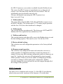
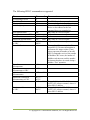
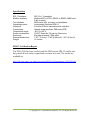
1
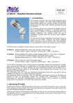
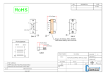
MS1-2150 Protocol Converter
User Manual
Firmware version 2.0
ISI
Instrumental Solutions, Inc.
WWW.ISIDEV.NET
Introduction
The MS1-2150 protocol converter can take readings from 1 or more
ModBus registers on up to 2 ModBus instruments using an RS485 or RS232
interface, and make that data available on a SDI-12 network. It is
preconfigured to read the Level, Velocity, Flow, Volume and Temperature
registers on an Isco 2150 Area Velocity Flow Module.
For special situations, the unit can be reconfigured via the text-based user
interface using most any terminal software.
Getting Started
All wiring connections are made inside the weatherproof enclosure, with the
wires passing through the waterproof fitting on the rear panel of the
enclosure.
Remove the rear panel by removing the 4 retaining screws and slide the
circuit board out to gain access to the connectors (see Figure 1). For testing
purposes, the 2150 can be plugged directly in to the DB9P connector labeled
“RS-232” using Isco’s Serial Communication cable (Isco Part #60-2004046, not included). However, permanent installations should use screw
terminals 4-6 labeled “GND”, “232 TX”, and “232 RX”, respectively. See
Tables 1 & 2 for more information on making electrical connections.
The DB9P connector is also used for configuring the MS1-2150. A nullmodem serial cable and terminal program (such as Hyperterm) is required to
do this. When configuring the MS1-2150, the Isco 2150 must be
disconnected from the converter. The MS1-2150 is preconfigured to operate
with the Isco 2150, and configuration is not normally required.
The converter has 2 multi-color LED indicators on the front panel for
indicating SDI-12 and Modbus data activity. The indicators light up green
when the converter is receiving data on the associated interface, and red
when the converter is sending data on the interface. These can be used to
help diagnose communication problems.
© Copyright 2011 Instrumental Solutions, Inc. All Rights Reserved
Figure 1
© Copyright 2011 Instrumental Solutions, Inc. All Rights Reserved
Pin 1
Pin 2
Pin 3
Pin 4
Pin 5
Pin 6
Pin 7
Pin 8
Pin 9
Table 1 - DB9P Connections
No connection
Receive data – RS232 input
Transmit data – RS232 output
DTR – internally tied to pin 6 for flow control loopback
Signal ground
DSR – internally tied to pin 4 for flow control loopback
RTS – internally tied to pin 8 for flow control loopback
CTS – internally tied to pin 7 for flow control loopback
No connection
Table 2 – Terminal Connections
#1
SDI-12 data line
#2
SDI-12 ground
#3
+12VDC input
#4
Ground
#5 Transmit data – RS232 output
#6 Receive data – RS232 input
#7
RS485 line A
#8
RS485 line B
Table 3 – Jumper J6
Jumper installed on 1 & 2 Enable RS-232 operation
Jumper installed on 2 & 3 Enable RS-485 operation
Default Configuration
To view the current configuration or configure the MS1-2150, make sure
that the jumper on header J6 (which is located immediately behind the
screw-terminal block) is in position 1-2. This is the normal position (RS-232
enabled) when using the MS1-2150 with an Isco 2150. Position 2-3 is used
when connecting to a device with a RS-485 interface. Please refer to Table 3
above and the highlighted portion in Figure 1, where the jumper is shown in
position 2-3 (RS-485 enabled).
© Copyright 2011 Instrumental Solutions, Inc. All Rights Reserved
Next, disconnect any wires that are connected to the RS-232 screw
terminals, then plug one end of a null-modem cable into the DB9P connector
on the converter, and the other end into an available serial port on a PC.
Terminal software should be set for 9600 baud, 8 data bits, no parity, and no
flow control.
To enter configuration mode, quickly type 3 question-mark characters. The
MS1-2150 should respond with the following screen:
NOTE: If the converter fails to respond, try again, typing as quickly as you
can. If still no response, remove and re-apply power to the converter while
watching the front panel LEDs. Both LEDs should immediately light up red,
then turn green after about half a second, then go out after another halfsecond. If this doesn’t happen, check the power wiring for proper voltage
and polarity. The MS1-2150 operates on 9-14 volts DC.
If the LEDs don’t light when power is applied, there is a problem with the
converter. If the LEDs light but there is still no response after typing
question marks, make sure that you are using a null-modem serial cable,
which crosses pins 2 & 3 between ends. If the unit fails to respond, there
may be a problem with the converter.
© Copyright 2011 Instrumental Solutions, Inc. All Rights Reserved
The default configuration returns fields to the SDI-12 master in the
following order:
Level, Velocity, Flow, Volume, and Temperature.
To change a configuration setting, type the number of the setting followed
by the Enter key. The configuration mode has an inactivity timeout of 1
minute. If at any point during configuration the user goes 1 minute without
typing anything, the converter automatically returns to normal online
operation. Setting changes are saved as they are entered, so any changes
completed during the configuration session will not be lost if a inactivity
timeout occurs.
The following section describes each setting in detail.
1. Modbus operations 1-12
Upon receiving a measurement request from the SDI-12 master, the
MS1-2150 executes a series of Modbus operations, as defined by these
settings. An operation can be 1 of 3 types: a Read type (which reads a
Modbus register on the attached sensor), a Write type (which writes a
Modbus register on the attached sensor), or a Test type (which repeatedly
reads a Modbus register on the attached sensor until the value read
matches a “test” value specified in the operation).
For example, to initiate a data sample on the Isco 2150, Modbus register
number 25 must be written to a 1, which tells the 2150 to take a sample.
Operation #1 accomplishes this:
1.
Modbus operation 1
[*] [W] [1] Take-reading flag,set
The [*] indicates that this particular operation is enabled. A disabled
operation appears as [ ].
The [W] indicates that this is a Write operation.
The [1] indicates that this operation uses virtual device 1. Virtual devices
are discussed in the Virtual Devices section below.
The “Take-reading flag,set” text is a plain-text description of what the
operation does.
To view or modify the details of a Modbus operation, type its menuselection number and hit Enter. For example, to view/modify operation
#1 (menu selection 1), type 1 and hit Enter. You will be led through the
following dialog:
© Copyright 2011 Instrumental Solutions, Inc. All Rights Reserved
1. Modbus operation 1
Enabled: Yes (Spacebar to change, Enter to accept)
The spacebar will toggle this setting between Yes and No. Press the
ENTER key to accept the setting and take you to the next step:
[Modbus register]
Current setting: 25
New setting:
Enter a new value for the Modbus register, or hit Enter with no entry to
keep the current setting. In this case, we are operating on register 25,
which is the take-reading flag register in the Isco 2150.
Data type: 16-bit signed integer
accept)
(Spacebar to change, Enter to
The spacebar steps through all of the data types supported by the MS12150. This setting must agree with the data type of the Modbus register
being referenced. In this case, register number 25 in the Isco 2150 has a
data type of 16-bit integer. Press the ENTER key to accept the setting and
take you to the next step:
Type of operation: Write
(Spacebar to change, Enter to accept)
The spacebar steps through the available types for this operation. In this
case, we want to Write to the specified register on the Isco 2150.
[Operation data]
Current setting: 1
New setting:
Enter the data value to write to the Modbus register. In this case, we write
a 1 to initiate a sample on the Isco 2150.
[Operation name]
Current setting: Take-reading flag,set
New setting:
This is a free-form text description of what the operation does. Hit Enter
with no entry to keep the current setting.
The final setting for a Modbus operation is to select the virtual device
that the operation will use. The default configuration has 1 virtual device
© Copyright 2011 Instrumental Solutions, Inc. All Rights Reserved
defined, “Isco 2150”. If there is more than one virtual device defined, the
spacebar is used to select the device to use. In this case, we want to use
the device named “Isco 2150”:
Virtual device: Isco 2150
accept)
(Spacebar to change, Enter to
So, Operation #1 initiates a data sample on the 2150. What happens now?
Operation #2 executes next. This is a Test type of operation that causes
the MS1-2150 to wait for the 2150 to make sample data available. It does
this by repeatedly reading Modbus register 25 on the 2150 and looking
for it to change from 1 (the value that was written to it by Operation #1)
to 0, which indicates that data is ready to be read. This operation will
wait up to half the SDI-12 data-ready time (defined in the virtual device)
for the test condition to become true.
After the Test operation finishes (whether due to the test condition
becoming true or a timeout occurring), the converter continues with
Operations 3 – 7, which are all Read-type operations. Each operation
reads a data field from the 2150, and returns them all to the SDI-12
master.
Virtual Devices
The MS1-2150 can support up to 2 SDI-12 addresses on the SDI-12
network, and 2 addresses on the Modbus network. A virtual device must
exist for each Modbus address to be used. The virtual device defines
operating characteristics such as the SDI-12 and Modbus addresses,
Modbus mode (ASCII/RTU), the Modbus function code used to read a
register, and the SDI-12 timeout value.
Basically, the virtual device controls the mapping of SDI-12 requests
(based on the SDI-12 address specified by the master) to Modbus
addresses. The MS1-2150 can answer to up to 2 SDI-12 addresses, and
map these to up to 2 Modbus addresses. The default configuration for the
MS1-2150 is one Virtual device that uses SDI-12 address 0, Modbus
address 2, Modbus ASCII mode, and a read function code of 3. This
configuration is required to work properly with the Isco 2150.
Another typical configuration is to set Virtual device 1 with SDI-12
address 0 and Modbus address 0, and Virtual device 2 with SDI-12
address 1 and Modbus address 1. When the SDI-12 master requests a
measurement from SDI-12 address 0, the MS1-2150 will answer it and
execute only the Modbus operations that are set to use Virtual device 1,
© Copyright 2011 Instrumental Solutions, Inc. All Rights Reserved
and the operations will be directed to Modbus device address 0.
Likewise, SDI-12 requests directed to SDI-12 address 1 will also be
answered, and only the Modbus operations that use Virtual device 2 will
be executed, using Modbus address 1. The result is 2 individual data
channels that have no interaction with each other.
Another possibility is to set the SDI-12 address the same in both virtual
devices. In this case, the MS1-2150 will answer only to that address, but
will execute all of Modbus operations (assuming they are enabled), even
if more than one Modbus device address is defined. The MS1-2150 will
then combine the data from both Modbus devices into a single SDI-12
response. This is particularly useful with Isco’s stackable devices, where
each device on the stack is automatically assigned a unique Modbus
address.
13. Virtual device 1
14. Virtual device 2
These options allow you to view and configure the virtual devices. The
following section describes each setting:
1. Virtual device name
This is the name that the user wants to assign to the virtual device. The
name shows up in the list of available devices when configuring a
Modbus operation.
2. SDI12 address
This is the address that the MS1-2150 will answer to on the SDI-12
network. The default value is 0. This value must match the address that
the SDI-12 master uses when attempting to communicate with the MS12150. If the SDI-12 master has the ability to scan the network for sensors,
this is the address that will be associated with MS1-2150 on the SDI-12
master.
3. SDI12 data-ready time
This is the maximum length of time in seconds that the Modbus device
should take to have data available after a measurement request. The
default value is 90. The MS1-2150 reports this value back to the SDI-12
master in response to a measurement request. The SDI-12 master must
wait this length of time before requesting data from the MS1-2150.
However, if the SDI-12 master issues a non-concurrent measurement
request (recommended), the MS1-2150 will issue a Service Request to
© Copyright 2011 Instrumental Solutions, Inc. All Rights Reserved
the SDI-12 master as soon as data is available from the Modbus device.
This causes the SDI-12 master to immediately issue a data retrieval
request, even if the data-ready time has not been reached. This can
significantly speed up the data retrieval cycle.
For more information concerning the SDI-12 protocol, see
http://www.sdi-12.org.
4. Modbus address
This is the address that the MS1-2150 will send Modbus requests to on
the RS232 interface. The default value is 2. To ensure proper operation
with the Isco 2150, this value should not be changed.
5. Modbus mode
This sets the Modbus operating mode. The choices are ASCII and RTU.
Modbus ASCII is required for use with the Isco 2150.
6. Modbus read function
This sets the function code that will be sent to the Modbus device to read
the data holding registers. This must be set to 3 for the Isco 2150.
15. Restore default settings
This selection resets all configuration parameters to the factory-default
settings.
16. Resume normal operation
This selection exits configuration mode and returns the converter to
online operation. Configuration mode has an inactivity timeout of 1
minute; if at any time after entering configuration mode no characters are
typed for 1 minute, the converter will automatically return to normal
online operation. If this occurs in the middle of configuring a Modbus
operation, no changes will be made to the configuration. Modbus
operation changes are not saved until the user has stepped through all of
the settings for the operation.
SDI-12 Commands
The MS1-2150 is compliant with version 1.3 of the SDI-12 specification,
which is the most recent version as of the firmware v2.0 release date.
© Copyright 2011 Instrumental Solutions, Inc. All Rights Reserved
The following SDI-12 commands are supported:
Name
Command
Acknowledge Active
Send Identification
Change Address
Address Query
a!
aI!
aAb!
?!
Start Measurement
Start Measurement w/CRC
Send Data
Additional Measurements
Additional Measurements
w/CRC
Start Verification
aM!
aMC!
aD0! … aD9!
aM1! … aM9! May result in a service request.
aMC1! …
May result in a service request.
aMC9!
aV!
The next Send Data command will
return MS1-2150 status information in
the format of 4 integer values. These
values represent the number of invalid
SDI-12 commands received, the number
of Modbus CRC errors, the number of
Modbus read timeouts, and the number
of timeouts that have occurred during a
Modbus “Test” operation.
aC!
Start Concurrent
Measurement
Start Concurrent
Measurement w/CRC
Additional Concurrent
Measurements
Additional Concurrent
Measurements w/CRC
Continuous Measurements
Continuous Measurements
w/CRC
Comment
See SDI-12 spec for response format.
Does not change device configuration.
Returns the address in the first Virtual
Device or the address for the last
command that was responded to.
May result in a service request.
May result in a service request.
aCC!
aC1! … aC9!
aCC1! …
aCC9!
aR0! … aR9!
aRC0! …
aRC9!
Not applicable with MS1-2150 –
a<CR><LF> always returned, where “a”
is the SDI-12 address.
Not applicable with MS1-2150 –
a<CR><LF> always returned, where “a”
is the SDI-12 address.
© Copyright 2011 Instrumental Solutions, Inc. All Rights Reserved
Specifications
SDI-12 interface:
Modbus interface:
Text interface:
Operating system:
Indicators:
Connections:
Temperature range:
Power requirements:
Enclosure:
External dimensions:
Weight:
SDI-12 v1.3 compliant
Modbus ASCII or RTU, RS232 or RS485, 9600 baud,
8-bit, no parity
9600 baud, 8-bit, no parity, no handshake
Instrumental Solutions ISOS-11
2 bicolor LEDs for transmit/receive indication
Internal screw terminals, DB9 male (DTE)
-40°C to +85°C
12VDC 35ma idle, 35 ma avg, 55ma max
Extruded aluminum, IP65 rated
7.52” (19.1cm) L, 3.48” (8.84cm) W, 1.85” (4.7cm) H
15 ounces
SDI-12 Verification Report
The MS1-2150 has been verified with the NR Systems SDI-12 verifier and
has passed all tests in the comprehensive sensor test suite. The results are
available at:
http://isidev.net/yahoo_site_admin/assets/docs/SDI12VerificationReport.310132059.pdf
© Copyright 2011 Instrumental Solutions, Inc. All Rights Reserved