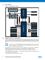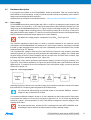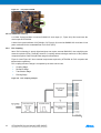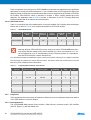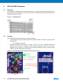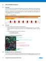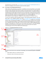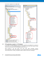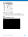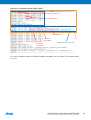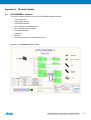
1
ATPL250A ATPL250A-EK Kit User Manual USER GUIDE Atmel-43083C-ATPL-ATPL250A-EK-Kit-User-Manual-UserGuide_24-Sep-2015 Introduction ATPL250A-EK is an evaluation kit for the G3-PLC modem for Power Line Communication from Atmel® Corporation. ATPL250A has a flexible architecture, composed of hardware accelerators and coprocessors, achieves a very efficient G3 PHY layer implementation. ATPL250AMB is PLC multi-purpose modem board based on the ATPL250A transceiver and on SAM4C ARM® Cortex™ M4 microcontroller. This development board provides a full featured platform to develop a complete communications system over Power Line Communication technology. This guide describes how to use the kit and get start with it. Contents Welcome letter that presents evaluation kit and the contents. Boards: you the Cables: Two micro A/B-type USB cables. Two power cord cables IEC320C8. Two ATPL250AMBv1 boards. modem Two ATPLCOUP007v2 board. coupling Two voltage jumpers with pitch 5.08 mm. Two ATPLCOUP006v1 boards. coupling Two erase jumpers with pitch 2.54mm. Jumpers: Features 2 ATPL250A is a compact and high-efficient device for a wide range of Smart Grid applications such as Smart Metering (Smart Meters and Data Concentrators), Lighting, Industrial/Home Automation, Home and Building Energy Management Systems, Solar Energy and Plug-in Hybrid Electric Vehicle (PHEV) Charging Stations. ATPL250A has been conceived to be bundled with an external Atmel MCU. ATPL250AMB modem board mounts the ATPL250A transceiver and on SAM4C ARM Cortex M4 microcontroller. This development board provides a full featured platform to develop a complete communications system over Power Line Communication technology. Evaluation platform performance for the Atmel ATPL250A to develop a complete communications system based on PLC technology: – Channel characterization. – Noise level measurement. – Sensitivity level measurement. – Maximum reachable distance. – Power consumption. – Possibility to verify the different standard frequency bands complying with the existing regulations (CENELEC, FCC, ARIB) setting the different PLC couplings boards. – A transformer lets you supplied the board with universal 115-230 VAC 50-60 Hz power input. – Boards have a JTAG interface for MCU debugging and programming purposes and two debugging UARTs. And also it provides Battery Backup and slow crystal oscillator to support SAM4C embedded Real time Clock (RTC) and low power modes. Several wake up ATPL250A-EK Kit User Manual [USER GUIDE] 2 Atmel-43083C-ATPL-ATPL250A-EK-Kit-User-Manual-UserGuide_24-Sep-2015 conditions are available, such mains crossover detection and voltage rails recovery condition. Software application examples available based on G3-PLC Stack: – Atmel provides an Atmel G3 PHY layer library which is used by the external MCU to take control of ATPL250A PHY layer device. Three example projects about the G3 PHY layer are provided with the kit. – And also the MAC and ADP layer to complete the Atmel G3-PLC Stack with two applications. ATPL250A-EK Kit User Manual [USER GUIDE] Atmel-43083C-ATPL-ATPL250A-EK-Kit-User-Manual-UserGuide_24-Sep-2015 3 3 Ta bl e of Conte nts 1. Evaluation Kit Specifications...................................................................................... 6 1.1 1.2 2. Evaluation Kit Overview .............................................................................................. 8 2.1 2.2 3. Overview ............................................................................................................................................. 26 Features .............................................................................................................................................. 26 Mechanical and user considerations ................................................................................................... 26 Hardware description .......................................................................................................................... 27 5.4.1 G3-PLC FCC channels - Double Branch ................................................................................ 27 ATPL250A Evaluation Kit: Getting started............................................................... 28 6.1 6.2 4 Overview ............................................................................................................................................. 24 Features .............................................................................................................................................. 24 Mechanical and user considerations ................................................................................................... 25 Hardware description .......................................................................................................................... 25 4.4.1 G3 channel 1 Single Branch ................................................................................................... 25 ATPLCOUP006 Hardware .......................................................................................... 26 5.1 5.2 5.3 5.4 6. Overview ............................................................................................................................................. 12 Features .............................................................................................................................................. 12 Block diagram ..................................................................................................................................... 14 Mechanical and user considerations ................................................................................................... 14 Hardware description .......................................................................................................................... 15 3.5.1 Power supply .......................................................................................................................... 15 3.5.2 ATPL250A PLC Transceiver................................................................................................... 17 3.5.3 SAM4C16C Flash Microcontroller .......................................................................................... 17 3.5.4 PLC Coupling ......................................................................................................................... 18 3.5.5 Peripherals ............................................................................................................................. 20 3.5.6 Interface Ports ........................................................................................................................ 22 ATPLCOUP007 Hardware .......................................................................................... 24 4.1 4.2 4.3 4.4 5. Design support ...................................................................................................................................... 8 ATPL250A-EK contents ........................................................................................................................ 8 ATPL250AMB Hardware ............................................................................................ 12 3.1 3.2 3.3 3.4 3.5 4. Safety recommendations....................................................................................................................... 6 Electrical characteristics ........................................................................................................................ 6 Introduction to the integrated development environment ..................................................................... 28 6.1.1 IAR Embedded Workbench .................................................................................................... 28 6.1.2 Atmel Studio 6 ........................................................................................................................ 28 6.1.3 Atmel SAM-ICE JTAG Probe .................................................................................................. 29 6.1.4 J-Link / SAM-ICE JTAG Probe Software & Documentation Pack ........................................... 29 6.1.5 Atmel Software Framework (ASF) .......................................................................................... 31 6.1.6 First steps with IAR Embedded Workbench ........................................................................... 32 6.1.7 First steps with Atmel Studio 6.2 ............................................................................................ 35 PLC application example 1 – PHY Tester ........................................................................................... 39 6.2.1 Atmel PLC PHY Tester tool Installation .................................................................................. 40 6.2.2 Supplying the boards .............................................................................................................. 43 6.2.3 USB connection ...................................................................................................................... 44 6.2.4 Programming the embedded file ............................................................................................. 45 ATPL250A-EK Kit User Manual [USER GUIDE] 4 Atmel-43083C-ATPL-ATPL250A-EK-Kit-User-Manual-UserGuide_24-Sep-2015 6.3 6.4 6.5 6.6 7. 6.2.5 Running the PLC application example 1 ................................................................................. 47 PLC application example 2 – PHY TX Test Console ........................................................................... 60 6.3.1 Supplying the boards .............................................................................................................. 60 6.3.2 USB connection ...................................................................................................................... 61 6.3.3 Programming the embedded file ............................................................................................. 61 6.3.4 Running the PLC application example 2 ................................................................................. 61 PLC application example 3 – PHY Sniffer ........................................................................................... 65 6.4.1 ATPL Multiprotocol Sniffer tool Installation ............................................................................. 66 6.4.2 Supplying the boards .............................................................................................................. 68 6.4.3 USB connection ...................................................................................................................... 68 6.4.4 Programming the embedded files ........................................................................................... 68 6.4.5 Running the PLC application example 3 ................................................................................. 69 Introduction to G3 Stack ...................................................................................................................... 72 6.5.1 FreeRTOS .............................................................................................................................. 72 6.5.2 ASF Integration....................................................................................................................... 73 6.5.3 Atmel G3-PLC Stack Structure ............................................................................................... 74 PLC application example 4 – PLC Network......................................................................................... 80 6.6.1 Supplying the boards .............................................................................................................. 81 6.6.2 USB connection ...................................................................................................................... 81 6.6.3 Programming the embedded files ........................................................................................... 81 6.6.4 Running the PLC application example 4 ................................................................................. 83 References ................................................................................................................. 86 Appendix A. Board schemes ........................................................................................ 87 A.1 ATPL250AMBv1 schemes .................................................................................................................. 87 A.2 ATPLCOUP007v2 schemes ................................................................................................................ 92 Revision History ............................................................................................................... 95 ATPL250A-EK Kit User Manual [USER GUIDE] Atmel-43083C-ATPL-ATPL250A-EK-Kit-User-Manual-UserGuide_24-Sep-2015 5 5 1. Evaluation Kit Specifications 1.1 Safety recommendations These development boards must be only used by expert technicians. ATPL250AMB is directly powered from mains grid, so hazardous voltage (100/230VAC) is present on the board. To avoid user access to dangerous parts, ATPL250AMB must always be used within its enclosure. All required connectors and configuration jumpers are easily accessible without electrical shock risk. A normal use of ATPL250AMB does not require removing the enclosure cover. If this action is necessary, it must be performed by qualified staff after being sure that mains connection has been previously removed. Be careful it is only for indoor use. This development board does not have any switch on mains connection to switch on or off it. It must always be connected to an easy accessible mains socket. Do not connect any probe to high voltage sections if the board is not isolated from the mains supply to avoid damaging of measurement instruments. This board can be used with coin lithium batteries, which are highly contaminated products. Used batteries must always be recycled. The boards’ kits are shipped in a protective anti-static package. The board system must not be subjected to high electrostatic discharge. We strongly recommend using a grounding strap or similar ESD protective device when handling the board in hostile ESD environments (offices with synthetic carpet, for example) without enclosure. Avoid touching the component pins or any other metallic element on the board. ATPL250AMB is a CE mark product which passes EN60950-1 safety standard and EN50065-1, EN50065-2-3, EN600065-7 EMC standards. It also satisfies Pb-Free and ROHS directive. ATMEL does not assume responsibility for the consequences arising from any improper use of this board. Boards’ kits are intended for further engineering, development, demonstration, or evaluation purposes only. It is not a finished product except as may be otherwise noted on the board/kit. 1.2 Electrical characteristics This section shows the electrical characteristics of the kit’s boards. See the following tables: Table 1-1. Power Supply Requirements. Parameter Condition AC mains Voltage Range Max. Unit 230 VAC 50/60 Maximum Input Current 6 Typ. 100 Mains Frequency Isolation Voltage Min. ACDC power supply and PLC coupling transformer ATPL250A-EK Kit User Manual [USER GUIDE] 6 Atmel-43083C-ATPL-ATPL250A-EK-Kit-User-Manual-UserGuide_24-Sep-2015 Hz 200(1) mA 3000 VAC Note that the ATPL250AMB can be supplied either with 100VAC or 230VAC by setting the proper jumpers (pitch = 5.08mm) in the voltage selector, J2, as depicted in the Figure 6-21. By default, voltage jumper is set for 230VAC. For more information about power supply, see section 3.5.1. Notes: 1. This current is measured when board is supplied with 100VAC and board is in worst consumption conditions. That is when it emits against very low impedance in higher channel and it is supplying an extra board through the DC jack J15. Table 1-2. Power Consumption. Parameter Condition Max Power Consumption ACDC maximum output power Min. Typ. Max. Unit 13 W FW PHY Tester Tool App Low Impedance Load (PRIME LISN) Measured on VDD (12V) DCDC output 2284(1) 4355(1) mW FW PHY Tester Tool App High Impedance Load (CISPR LISN) Measured on VDD (12V) DCDC output 1392(1) 1880 (1) mW Measured on 3.3V LDO output 397(1) mW < 1 (2) µA TX Power Consumption RX Power Consumption Low Power Mode Current Consumption Notes: 1. These measurements were taken with a non-optimized FW (with the PHY TX Test Console project included in the kit using a default configuration in RX mode and a differential robust modulation scheme and data random with a length of 100 bytes of payload in TX mode) from a power consumption point of view and they highly depend on the architecture of the power supplies. These measurements correspond to the whole PCBA design and not only to ATPL250A device. All PCB peripherals are supplied, i.e. SAM4C16C and ATPLCOUP007 coupling board is emitting in channel 1. Refer to Atmel ATPL250A datasheet for an optimized power consumption measurement result. 2. Output current of a 3Volts CR1225 battery. ATPL250A-EK Kit User Manual [USER GUIDE] Atmel-43083C-ATPL-ATPL250A-EK-Kit-User-Manual-UserGuide_24-Sep-2015 7 7 2. Evaluation Kit Overview ATPL250A is a G3-PLC modem for Power Line Communication that implements G3 CENELEC-A, FCC and ARIB profiles. It has been conceived to be bundled with an external Atmel MCU. ATPL250A is oriented in a wide range of Smart Grid applications such as Smart Metering, Lighting, Industrial/Home Automation, Home and Building Energy Management Systems, Solar Energy and Plugin Hybrid Electric Vehicle Charging Stations. ATPL250AMB is PLC multi-purpose modem board based on the ATPL250A transceiver and on SAM4C ARM Cortex M4 microcontroller. This development board provides a full featured platform to develop a complete communications system over Power Line Communication technology. This document describes how to starting to work with the Atmel ATPL250-EK by explaining the PC tools, software examples and hardware provided and giving you the necessary documents to create your PLC application by means of small and easy examples. 2.1 Design support To make it faster and easier for you to evaluate, prototype, develop and program with Atmel® products, we offer a variety of design resources, including development tools, software, boards, kits and documentation. For any technical support request, http://www.atmel.com/design-support/. please refer to our Design Support webpage: There any user can search the Atmel knowledge base to find tips, help topics, and answers to common questions. In case that the obtained information is not helpful any user can Open a Support Case indicating a description of the case, product information, etc. 2.2 ATPL250A-EK contents Additional information of this user guide as hardware documentation, software projects and PC tools to get started can be found in our Atmel website, http://www.atmel.com/tools/ATPL250A-EK.aspx. To download this information you need a myAtmel account, www.atmel.com/myAtmel. After that, please contact with [email protected] to get the password access kit contents site. Once you have access to the ATPL250A Evaluation Kit Project you can find the available releases for the ATPL250A-EK. You can get these items, navigating through the different folders of the packing kit. Please do not hesitate to visit our web site to get the last kit updates. Packing kit contents are: 1. A welcome letter, ATPL250A-EK_WL, which presents you the evaluation kit and the contents. 2. ATPL250A-EK Kit User Manual, doc43083. 3. Hardware folder contents: a. ATPL250A datasheet, doc43079. b. Some application notes about hardware issues: different Atmel PLC coupling boards, crystal selection guidelines, layout recommendations, critical design guidelines, etc. c. Schemes, PCBs layout, Gerbers and BOM files of ATPL250AMB, ATPLCOUP007 and ATPLCOUP006 boards. 4. Software folder contents: a. G3_va.b.c_CENELEC folder which contains a workspace for IAR and Atmel Studio with five projects in an unique file to work in CENELEC-A frequency band, see g3.workspace.sam4c16c_atpl250amb.zip file: 8 Apps_Phy_Tester_Tool. This application configures G3 PHY layer and its serial interface to communicate with Atmel PLC PHY Tester Tool to send and receive PLC ATPL250A-EK Kit User Manual [USER GUIDE] 8 Atmel-43083C-ATPL-ATPL250A-EK-Kit-User-Manual-UserGuide_24-Sep-2015 messages from/to the PLC line and check the PLC transmission/reception processes between ATPL250AMB boards. Apps_Phy_Tx_Test_Console. This application lets the user to configure a proper set up to perform both EMC emissions and immunity tests on ATPL250AMB board. These tests are based on the use of G3 PHY layer with a terminal console firmware that eases the configuration of several transmissions. Apps_Phy_Sniffer_Tool. This application configures G3 PHY layer to monitor the PLC data traffic on ATPL250AMB boards and sends via serial communication this traffic to the ATPL Multiprotocol Sniffer tool. Every coupling board is intended to be used in their corresponding channel(s) only. APPS_DLMS_EMU_COORD_APP and APPS_DLMS_EMU_DEV_APP. The DLMS Emulator applications are examples using the Atmel G3-PLC stack and show how the G3 API should be used. These applications are provided for both, Device and Coordinator. Applications configure the ATPL250AMB board as Nodes with DLMS Emulation capabilities and simulate the data exchange between the G3 Coordinator and the Device(s). The Device responds dummy DLMS messages after receiving data requests from the Coordinator. b. G3_va.b.c_FCC folder which contains a workspace for IAR and Atmel Studio with five projects in an unique file to work in FCC frequency bands, see g3.workspace.sam4c16c_atpl250amb.zip file: c. Apps_Phy_Tester_Tool. This application configures G3 PHY layer and its serial interface to communicate with Atmel PLC PHY Tester Tool to send and receive PLC messages from/to the PLC line and check the PLC transmission/reception processes between ATPL250AMB boards. Apps_Phy_Tx_Test_Console. This application lets the user to configure a proper set up to perform both EMC emissions and immunity tests on ATPL250AMB board. These tests are based on the use of G3 PHY layer with a terminal console firmware that eases the configuration of several transmissions. Apps_Phy_Sniffer_Tool. This application configures G3 PHY layer to monitor the PLC data traffic on ATPL250AMB boards and sends via serial communication this traffic to the ATPL Multiprotocol Sniffer tool. Every coupling board is intended to be used in their corresponding channel(s) only. APPS_DLMS_EMU_COORD_APP and APPS_DLMS_EMU_DEV_APP. The DLMS Emulator applications are examples using the Atmel G3-PLC stack and show how the G3 API should be used. These applications are provided for both, Device and Coordinator. Applications configure the ATPL250AMB board as Nodes with DLMS Emulation capabilities and simulate the data exchange between the G3 Coordinator and the Device(s). The Device responds dummy DLMS messages after receiving data requests from the Coordinator Common software documentation folder. It contains some application notes as the description of the Atmel G3 firmware stack. It describes in detail all layers from the Atmel G3 implementation as well as configuration options provided by Atmel. d. Evaluation License Agreement document. 5. PCTools folder contents: a. Atmel PLC PHY Tester tool, for checking the point to point PLC transmissions between ATPL250AMB boards. b. ATPL Multiprotocol Sniffer tool to monitor data traffic on G3 networks and gather information of a G3 network. ATPL250A-EK Kit User Manual [USER GUIDE] Atmel-43083C-ATPL-ATPL250A-EK-Kit-User-Manual-UserGuide_24-Sep-2015 9 9 c. SAM-ICE™ Drivers. Users may need to install this driver the first time the SAM-ICE is connected to the PC. d. USB Drivers (Silicom usb drivers). Users may need to install these drivers the first time the ATPL250AMB board is connected to the host PC by means of a serial USB connection. We recommend installing the evaluation kit contents in the root C:\ to avoid problems with very long paths. Unpack and inspect the kit carefully. Contact your local Atmel distributor, should you have any issues concerning the contents of the kit. The two ATPL250AMB boards with the ATPLCOUP007 are encapsulated with enclosures and shipped in protective anti-static foam. The two coupling boards, ATPLCOUP006, are shipped in shielded bags. The boards must not be subject to high electrostatic discharge. We recommend using a grounding strap or similar ESD protective device when handling the board in hostile ESD environments. Avoid touching the components pins or any other metallic elements on the board. Note that kit does not provide any battery. The coin battery is provided for user convenience in case the user would like to exercise the date and time backup function of the SAM4C device when the board is switched off. Figure 2-1. Packed Atmel ATPL250A-EK. 10 ATPL250A-EK Kit User Manual [USER GUIDE] 1 Atmel-43083C-ATPL-ATPL250A-EK-Kit-User-Manual-UserGuide_24-Sep-2015 0 Figure 2-2. Unpacked Atmel ATPL250A Evaluation Kit. Figure 2-3. ATPL250AMB board and an ATPLCOUP007 board. Both ATPL250AMB boards are provided with an example application preprogrammed, the PHY Tester embedded software for SAM4C16C. After installing the Atmel PLC PHY Tester Tool in your PC, users can interface with the device and start exploring its capabilities, for example, checking the point to point PLC transmissions between the two ATPL250AMB boards. Take into account that the ATPL250A-EK provides two coupling boards for CENELEC-A band set over the ATPL250AMB board. In addition to the ATPLCOUP007 boards, evaluation kit adds two coupling boards for FCC bands, ATPLCOUP006. Atmel PLC PHY Tester Tool lets you send and receive PLC messages with both coupling boards according to the board selected in the PC tool. And depending on the board selected you will select the PHY parameters and the PLC channel. So that, with ATPLCOUP007 board only lets you send and receive PLC messages in CENELEC-A band. And with ATPLCOUP006 board in FCC bands. Please refer to chapter 6.2 for further information. ATPL250A-EK Kit User Manual [USER GUIDE] Atmel-43083C-ATPL-ATPL250A-EK-Kit-User-Manual-UserGuide_24-Sep-2015 11 1 1 3. ATPL250AMB Hardware 3.1 Overview This section summarizes the Atmel ATPL250AMB board design. It introduces system-level concepts, such as power supply, MCU, PLC coupling, peripherals and interface board. ATPL250AMB is a G3 multi-purpose development board based on the ATPL250A G3-PLC transceiver and on the SAM4C16C ARM Cortex-M4 microcontroller. ATPL250AMB modem board provides a platform to develop a complete communications system over G3-PLC technology. Figure 3-1. ATPL250AMB board. 3.2 Features The ATPL250AMBv1 board includes the following features: 12 Power supply: – Non switched ACDC isolated power supply: 100-230VAC, 50-60Hz. – 5 volts rail is accessible by means of a DC Jack connector (J15). ATPL250A G3 PLC Transceiver: – Implements G3 CENELEC-A, FCC and ARIB profiles (ITU-T G.9903, June 2014). – Power Line Carrier modem for 50 and 60 Hz mains. – G3-PLC coherent and continuous amplitude tracking in signal reception. – – Automatic Gain Control (AGC) and continuous amplitude tracking in signal reception. Embedded PLC Analog Front End (AFE), requires only external discrete high efficient Class D Line Driver for signal injection. Support to PLC coupling boards ATPLCOUPXXX. Mains zero-crossing detector circuit. SAM4C16C MCU ARM Cortex-M4. External Memories: ATPL250A-EK Kit User Manual [USER GUIDE] 1 Atmel-43083C-ATPL-ATPL250A-EK-Kit-User-Manual-UserGuide_24-Sep-2015 2 – Serial EEPROM (do not populate). – DataFlash memory. Peripherals: – Voltage monitor. – Back-up battery holder. – User’s LEDs. – Force Wake Up switch button. – Tamper switch button. – Reset button. Interface: – JTAG debugging port. – Xplained PRO Master/Slave Interface. – UARTs over USB and CMOS levels. – ATPL250A SPI. – Control of 3V3 power supply. Figure 3-2. ATPL250AMB multi-purpose modem board. ATPL250A-EK Kit User Manual [USER GUIDE] Atmel-43083C-ATPL-ATPL250A-EK-Kit-User-Manual-UserGuide_24-Sep-2015 13 1 3 3.3 Block diagram Figure 3-3. ATPL250AMB Block diagram. ATPLCOUPxxx Board 3V3 SPI + INT DC/DC RECTIFIER MAINS 115/230 VAC Zero Crossing 24MHz Crystal SPI + INT + RST 3V3 RESET 12MHz Crystal Slow Clock Crystal BACK-UP BATTERY 2Kb EEPROM TWI User LED’s GPIOs FWUP & TMP0 3.4 SAM4C16C Zero Crossing SHDN SPI + INT + RST 12MHz CLK VDD ATPL250A PLC USART0 BN/MIMO JTAG JTAG SPI1 & USART1 Xplained PRO UART0 & UART1 UARTs CMOS UART To USB SPI (USART2) B Micro USB Port DataFlash 32 Mb Voltaje Monitor ERASE Mechanical and user considerations This development board is directly powered from mains grid, so hazardous voltage is present on the board. To avoid user access to dangerous parts, ATPL250AMB must always be used in its enclosure. All required connectors and configuration jumpers are easily accessible without removing the enclosure cover. A normal use of the ATPL250AMB does not require removing the enclosure cover. If this action is necessary, it must be performed by qualified staff being sure that mains connection has been previously removed. ATPL250AMB is a CE mark product which passes EN60950-1 safety standard and EN50065-1, EN50065-2-3, EN600065-7 EMC standards. It also satisfies Pb-Free and ROHS directive. ATPL250AMB supply voltage is taken from mains grid (100/230VAC, 50-60Hz), J1 connector. ATPL250AMB dimensions are 165mm x 114mm x 30mm (LxWxH) and the enclosure dimensions are 179mm x 130mm x 50mm (LxWxH). The operating temperature range is about -10 to 85ºC. 14 ATPL250A-EK Kit User Manual [USER GUIDE] 1 Atmel-43083C-ATPL-ATPL250A-EK-Kit-User-Manual-UserGuide_24-Sep-2015 4 3.5 Hardware description In this section the modules of the ATPL250AMBv1 board are described. Take into account that the board’s BOM; is not a final design, so they include devices that could be no necessary in the customer designs once the design has been optimized. Hardware files are contained in the Hardware folder: “.\Hardware\HW_SCH&PCB\ATPL250AMBv1”. 3.5.1 Power supply ATPL250AMB board can be powered either with 100V AC or 230VAC by setting the proper jumpers in the voltage selector (J2, Figure A-2). J1 IEC-320-C8 connector allows cable connection to mains grid. This design uses an encapsulated transformer (T1, Figure A-2) plus a full bridge rectifier (D1, Figure A-2) to obtain a DC voltage without increasing noise in PLC frequency bands (42 to 472 kHz), as may occur with switched ACDC power supplies. F1 and VR1 are used as protective devices in the equipment input and F2 protects the transformer output against over current situations. By default, the voltage jumpers’ configuration is for 230VAC. See Figure 6-21. The maximum transformer output power of 14VA is oversized compared to the maximum current consumption of ATPL250AMB when it is used as a PLC service node. However, this design is intended to power up other development kits which may have considerable power consumption if they include components such as TFT displays. The unregulated DC voltage is used as input of the DCDC buck converter -high frequency step-down switching regulator (U11, Figure A-2) which generates the configurable VDD voltage. VDD is mainly used as power supply of the PLC class D amplifier and also as input of the 5V DCDC buck converter -high frequency step-down switching regulator (U12, Figure A-2). 5V voltage rail is only used to provide an external power supply by means of DC jack connector (J15, Figure A-8). 3V3 is linearly regulated (U13, Figure A-2) and is used to power up ATPL250A and all other digital devices. To measure the current consumption of the 3volts power supply, connect an ammeter instead of the jumper J17. Figure 3-4. Power supply diagram. Switching frequency of DCDC buck converters used in this evaluation kit has been chosen to be higher than maximum PLC frequency band supported by ATPL250A device. We recommend characterizing the potential impact of the selected SMPS for customer designs on the G3 transmission channel. VDD could be two different voltages, 16volts or 12 volts, depending on the jumper position. If the jumper is not placed, the voltage VDD is 16 volts. If the jumper is placed in J16, VDD is 12 volts. By default, the board has a jumper, so board provides 12 volts. These different voltages are used to supply the PLC coupling driver board. Be careful with this issue, because the PLC coupling driver board ATPLCOUPXXX could be damaged. See the features of these boards to know the working voltage. ATPL250A-EK Kit User Manual [USER GUIDE] Atmel-43083C-ATPL-ATPL250A-EK-Kit-User-Manual-UserGuide_24-Sep-2015 15 1 5 Figure 3-5. VDD selection in ATPL250AMB board. Jumper configuration Jumper J16 ATPL250AMB can also be powered from USB connector (J9, Figure A-8) or Xplained PRO interface (J12) without requiring connection to mains. Note that in these cases V DD is not available so the PLC amplifier cannot be used. The following test points and LEDs allow checking that these power supplies are running properly (see Figure A-2): VDD: TP6 and green LED D17. 5V: TP5 and green LED D3. 3V3: TP13 and green LED D13. GND: TP3 & TP4. 3.5.1.1 Control of 3.3 volts power supply The ATPL250AMB provides activate or deactivate the 3.3 volts regulator by SHUTDOWN pin, SHDN. User can be deactivate the 3.3 volts regulator before enter in a low mode power consumption of SAM4C16C, that can be powered by the battery. This allows decrease the consumption of the board. J4 lets us enable the 3.3 volts regulator always, independently of SHDN pin. By default this option is deactivated, 3v3 is always on, independently of the value of SHDN, to activate this option remove the jumper in J4 (Figure A-6). Figure 3-6. J4 enabling 3.3 volts jumper. 16 ATPL250A-EK Kit User Manual [USER GUIDE] 1 Atmel-43083C-ATPL-ATPL250A-EK-Kit-User-Manual-UserGuide_24-Sep-2015 6 By default, jumper J4 is set. 3.5.1.2 Zero crossing detector A simple isolated circuitry (U10, Figure A-2) is used to detect mains zero crossing events. This VNR signal is used directly in the ATPL250A (VZ Cross) as well as in SAM4C16C microcontroller through an input (PB11) port as another wake up condition. 3.5.2 ATPL250A PLC Transceiver 3.5.2.1 ATPL250A Overview The ATPL250AMB includes an ATPL250A (U1, Figure A-3) PLC transceiver that is a G3-PLC base band modem for Power Line Communication. ATPL250A flexible architecture composed of hardware accelerators and coprocessors achieves a high-efficient PLC PHY layer implementation and still provides some level of flexibility to implement customized PHY solution. ATPL250A has been conceived to be bundled with an ATMEL MCU running the Physical Layer API and being controlled by means of a serial synchronous communication interface (SPI). Please refer to ATPL250A datasheet on the Atmel website or in doc43079 for a detailed description. 3.5.2.2 ATPL250A Clocking ATPL250A requires a 24MHz crystal oscillator (Y3, Figure A-3). And SAM4C16C requires a 12 MHz crystal oscillator (Y1, Figure A-6). The 24MHz clock signal could be used as internal reference time of the PLC modem, ATPL250A, and also to generate a 12MHz. So, it could be connected the output clock signal (CLKOUT) of ATPL250A like an input clock (CLKIN) of SAM4C16C when ATPL250A is configured in bypass mode. In this way, only one high frequency crystal oscillator is required. For this option that is mounted by default in the board, R85 is soldered but R67 and R68 are not populated, and remember that ATPL250A must be configured properly. Clocking item is widely detailed in the datasheet, doc43079. 3.5.3 SAM4C16C Flash Microcontroller 3.5.3.1 SAM4C16C Overview The Atmel SAM4C16C microcontroller (U4, Figure A-6) is a system-on-chip solution for smart energy applications, built around two high-performance 32-bit ARM Cortex-M4 RISC processors. It operates at a maximum speed of 120 MHz and feature up to 1MB of embedded Flash, 152 Kbytes of SRAM and on-chip cache for each core. The peripheral set includes advanced cryptographic engine, anti-tamper, floating point unit (FPU), five USARTs, two UARTs, two TWIs, up to seven SPIs, as well as a PWM timer, two 3-channel generalpurpose 16-bit timers, temperature compensable low power RTC running on backup area down to 0.5 μA, and a 50 x 6 segmented LCD controller. The ERASE pin can be used to reinitialize the Flash content, so setting a jumper in J14 connector (Figure A-6), the flash content is erased. This pin integrates a pull-down resistor of about 100kΩ, so that, it can be left unconnected for normal operations. When the ERASE pin is tied high during less than 100 ms, it is not taken into account. The pin must be tied high during more than 220 ms to perform a Flash erase operation. Please refer to SAM4C datasheet, doc11102, for a further description on Atmel’s website. ATPL250A-EK Kit User Manual [USER GUIDE] Atmel-43083C-ATPL-ATPL250A-EK-Kit-User-Manual-UserGuide_24-Sep-2015 17 1 7 Figure 3-7. J14 jumper, ERASE. 3.5.3.2 SAM4C16C Clocking A 12 MHz Crystal oscillator is used as SAM4C16C clock input (Y1, Figure A-6). But board uses the clock output of ATPL250A. A slow clock crystal oscillator of 32.768 kHz (Y2, Figure A-6) is used as SAM4C16C clock base in low power mode and for the embedded Real Time Clock (RTC). 3.5.4 PLC Coupling Atmel PLC technology is purely digital and does not require external DAC/ADC, thus simplifying the external required circuitry. Generally Atmel PLC coupling reference designs make use of few passive components plus a Class D amplification stage for transmission. Figure A-4 and Figure A-5 show external components required by ATPL250A for PLC reception and transmission respectively. PLC coupling reference design is composed by the same sub-circuits: Coupling Stage. Reception Stage. Transmission Stage. Filtering Stage Figure 3-8. PLC Coupling example. 18 ATPL250A-EK Kit User Manual [USER GUIDE] 1 Atmel-43083C-ATPL-ATPL250A-EK-Kit-User-Manual-UserGuide_24-Sep-2015 8 3.5.4.1 Coupling stage The coupling stage blocks the DC component of the line to/from which the signal is injected / received (i.e.: 50/60 Hz of the mains). This is carried out by a high voltage capacitor (C26, Figure A-4). Coupling stage could also voltage isolate the coupling circuitry from the external world by means of a 1:1 PLC transformer. Capacitor is laying out in ATPL250AMB. The optional PLC transformer is included in ATPLCOUP007 board (voltage isolated), see chapter 4. Footprint of BNC connector (J11, Figure A-4) is included in the board, but is not mounted by default. Removing the R12 and R13 and soldering R88 and R89 resistors, the PLC coupling signal can be isolated from the mains grid and that connector allows performing measurements of transmitted and received PLC signal without side effects (noise) coming from the grid. 3.5.4.2 Reception stage The reception stage adapts the received analog signal to be properly captured by the internal reception chain. Reception circuit is independent of the PLC channel which is being used. It basically consists of: Anti-aliasing filter (RC Filter), R49 & C43, Figure A-5. Automatic Gain Control (AGC) circuit. The AGC circuit avoids distortion on the received signal that may arise when the input signal is high enough to polarize the protective diodes in direct region (D10, Figure A-5). Driver of the internal ADC. The driver to the internal ADC comprises a couple of resistors and a couple of capacitors. This driver provides a DC component and adapts the received signal to be properly converted by the internal reception chain. 3.5.4.3 Transmission stage The transmission stage adapts the EMIT signals and amplifies them if required (Figure A-4). It can be composed by: Driver: A group of resistors which adapt the EMIT signals to either control the Class-D amplifier or to be filtered by the next stage. Amplifier: If required, a Class-D amplifier which generates a square waveform from 0 to VDD is included. Bias and protection: A couple of resistors and a couple of Schottky barrier diodes provide a DC component and provide protection from received disturbances. Transmission stage shall be always followed by a filtering stage. 3.5.4.4 Filtering stage The filtering stage is composed by band-pass filters which have been designed to achieve high performance in field deployments complying at the same time with the proper normative and standards. The in-band flat response filtering stage does not distort the injected signal, reduces spurious emission to the limits set by the corresponding regulation and blocks potential interferences from other transmission channels. The filtering stage has three aims: Band-pass filtering of high frequency components of the square waveform generated by the transmission stage. Adapt Input/Output impedances for optimal reception/transmissions. This is controlled by TXRX signals. And, in some cases, Band-pass filtering for received signals. When the system is intended to be connected to a physical channel with high voltage or which is not electrically referenced to the same point then the filtering stage must be always followed by a coupling stage. ATPL250A-EK Kit User Manual [USER GUIDE] Atmel-43083C-ATPL-ATPL250A-EK-Kit-User-Manual-UserGuide_24-Sep-2015 19 1 9 These components are not lying out on ATPL250AMB board because are dependent on the application parameters such frequency band transmission. A set of boards known as ATPLCOUPXXX have been design by Atmel to implement any possible transmission scheme supported by ATPL250A. ATPL250AEK includes ATPLCOUP007 which is described in chapter 4. Other coupling boards have been designed. The Application Note doc43052 provides a description of the PLC Coupling Reference Designs available and all the features and characteristics. 3.5.4.5 ATPLCOUP boards Table 3-1 summarizes the main characteristics of currently available PLC coupling reference designs. Please refer to Atmel doc43052 for a complete description of ATPLCOUP boards. Table 3-1. ATPLCOUP boards. Board Name Frequency Band Branch Electrical Isolation G3-PLC Channel CENELEC Band ATPLCOUP006 151-472 kHz Double Yes 3, 4, 5, 6, 7,8 - ATPLCOUP007 35-89 kHz Single Yes 1 A - - ATPLCOUP008 35-89 kHz Single No 1 A - - ARIB FCC X Although different ATPLCOUPXXX can be used on the same ATPL250AMB board, they may require different voltage for the class D amplifier (VDD). As is commented in 3.5.1, VDD can be regulated to 16 or 12 volts depending on the J16 jumper position. It is important to note that ATPLCOUP007 must be used with 12V. The ATPL250A provides the ARIB/FCC frequency band and it allows choosing up to 8 different channels. This technology only allows one channel active at a time. The limits of each channel are shown in the next table and can be compared with the table above. Table 3-2. 3.5.5 Frequency Band limits for each channel. Channel Start freq. (kHz) End freq. (kHz) CENELEC ARIB FCC 1 41,992 88,867 X X X 2 96,68 143,555 X X X 3 151,367 198,242 - X X 4 206,055 252,93 - X X 5 260,742 307,617 - X X 6 315,43 362,305 - X X 7 370,117 416,992 - X X 8 424,805 471,68 - - X Peripherals These peripherals are not necessary to implement a G3 device, they are included to show some features of the ATPL250A for a customer designs. 3.5.5.1 External Memories The ATPL250AMB Multi-purpose board includes a Flash Memory connected mean a SPI interface (U3/U12, Figure A-7) with the SAM4C16C. 20 ATPL250A-EK Kit User Manual [USER GUIDE] 2 Atmel-43083C-ATPL-ATPL250A-EK-Kit-User-Manual-UserGuide_24-Sep-2015 0 The ATPL250AMB Multi-purpose board includes the possibility to mount a serial EEPROM memory connected by Two Wires Interface (U2, Figure A-7) with the SAM4C16C. Please refer to AT24Cxx datasheet for a further description on Atmel’s website. 3.5.5.2 SAM4C MCU Real Time Clock and back-up battery SAM4C16C MCU embedded Real Time Clock (RTC) can be used as calendar and time base counter. A back-up battery (Figure A-6), slow clock crystal and low power modes are required to keep the RTC running during power down or mains unplugged conditions. The ATPL250AMB includes a Battery (BT1, Figure A-6) for maintain active the RTC when the power supply of 3v3 shutdown and SAM4C16C enter in a low-power mode. J18 jumper lets us supply the board with the battery setting the jumper between VDDBU and BATT position. Figure 3-9. J18 jumper in battery position. By default jumper J18 sets VDDBU to 3V3 supply. 3.5.5.3 Voltage Monitor The ATPL250AMB monitors VDD and 5V voltage rails to detect backup mode entering conditions and also wake up events by means of its dedicated hardware. 5V falling condition is the most recommended trigger event to enter backup mode on ATPL250AMB design: Configure PB23 as positive input of analog comparator and compare it with AREF. Once 5V rail falls below 4.5V (depending on R70, R74 values) (i.e., mains grid connection has been removed) the analog comparator interrupt is triggered. Before going to backup mode, configure PB23 as wake up port to return to active mode once power supply is available again. The wake-up events allow the microcontroller to exit the backup mode. When a wake-up event is detected, the Supply Controller performs a sequence which automatically enables the core and the SRAM power supply and clocks. See Figure A-7 for details. Lack of activity on VZ CROSS signal (PB11) can also be used to enter in backup mode. 3.5.5.4 Tamper and Wake-Up The purpose of backup mode is to achieve the lowest possible power consumption in a system that executes periodic wake-ups to perform tasks but which does not require fast start-up time. Wake-up events allow the device to exit backup mode. Force Wake-Up pin, FWUP, can be used as a wake-up source. In ATPL250AMB board, FWUP has been connected to switch button SW3. Anti-tamper pins (TMP0-TMP3) detect intrusion, for example, into a smart meter case. Upon detection through a tamper switch, automatic, asynchronous and immediate clear of registers in the backup area, and time stamping in the RTC will be performed. Anti-tamper pins can be used in all modes. Date and ATPL250A-EK Kit User Manual [USER GUIDE] Atmel-43083C-ATPL-ATPL250A-EK-Kit-User-Manual-UserGuide_24-Sep-2015 21 2 1 number of tampering events are stored automatically. Tampering input 0, TMP0, is connected to switch button SW2. Wake up pins multiplexed with anti-tampering functions are possible sources of wake up as well in case an anti-tampering event is detected. 3.5.5.5 User leds The board incorporates two user LEDs (LED0 & LED1), green and red (D5 & D6, Figure A-7), connected to PB14 and PB15 respectively of the SAM4C16C. 3.5.6 Interface Ports 3.5.6.1 Reset circuitry ATPL250AMB can be manually reset by using a push button (SW1, Figure A-8) or by means of an external reset signal available on the Base Node/MIMO interface connector. This reset restarts the SAM4C16C and the ATPL250A include his PLL. Also ATPL250A shall be reset from SAM4C16C with an asynchronous reset by PC6 and with a synchronous reset by PC7, see Figure A-8. 3.5.6.2 ATPL250A SPI ATPL250AMB provides the option to connect the SPI, the Reset and the interruption signal of ATPL250A device with an external microcontroller. This option is available in a 5-pin dual row male header (J3, Figure A-8) allowing others Atmel development boards make use of the ATPL250A PLC transceiver. For enable this option is necessary do not placed R17, R32, R35, R39 and R41 and solder R2, R18, R33, R38, R40, R42 and R50. It is recommended to avoid unintentional reset, do not placed R43, R44 and R45. 3.5.6.3 SAM4C JTAG Debug Port The SAM4C16C JTAG interface is available in a standard 20-pin male header J13 (see Figure A-8) for debugging and programming purposes. The JTAG/ICE connector is implemented on the ATPL250AMB board for the connection of a compatible ARM JTAG emulator interface, such as the SAM-ICE from Segger. Notes: 1. The NRST signal is connected to SW1 system button and also to an external reset signal available on the Base Node/MIMO interface connector. 2. The 0 ohm resistor R26 may be removed in order to isolate the JTAG port from this system reset signal. 3. The TDO pin is in input mode with the pull-up resistor disabled when the Cortex M4 is not in debug mode. To avoid current consumption on VDDIO and/or VDDCORE due to floating input, the internal pull-up resistor corresponding to this PIO line must be enabled. Please refer to the SAM4C16C datasheet for a further description of JTAG debug port. 3.5.6.4 Debugging UARTs ATPL250AMB uarts, UART0 and UART1, are user accessible by means of micro USB type B connector (J9, Figure A-8). A single chip bridge is used to convert UARTs TTL CMOS to USB levels (U8, Figure A-8). Note that this bridge is powered from USB 5V power supply, so it is only available when USB cable is attached to any other USB host port. That single chip drive, CP2105-F01-GM of Silicom Labs, has two ports. The enhanced port is connected to UART0 and the standard port is connected to UART1. It is possible to power ATPL250AMB directly from USB connector. However, due to power limitations, this option does not allow PLC transmissions. Nevertheless, this option is very useful for several applications such as FW downloading or debugging. Furthermore, UARTs CMOS signals are also available in a triple row male connector (J5, Figure A-8). 22 ATPL250A-EK Kit User Manual [USER GUIDE] 2 Atmel-43083C-ATPL-ATPL250A-EK-Kit-User-Manual-UserGuide_24-Sep-2015 2 3.5.6.5 Xplained PRO Master Xplained Pro is an Atmel’s proprietary interface port intended to connect different development boards, such as metering and PLC communication boards. This point-to-point interface offers SPI and USART communication capabilities and requires one target board (master) and an extension module (slave). ATPL250AMB is an Xplained Pro target device with power supply extension connector. ATPL250AMB Xplained Pro provides the following features: SPI (from the SPI1). UART (from the USART1). I2C (from the TWI0) 2 ADC inputs (from PA4 and PB13). 1 IRQ input (from PA17). 5 GPIO’s (from PA18, PB19, PB20, PB21 and PC8). ATPL250AMB is an Xplained Pro Master device with power supply extension connector (J12, Figure A8). ATPL250A-EK Kit User Manual [USER GUIDE] Atmel-43083C-ATPL-ATPL250A-EK-Kit-User-Manual-UserGuide_24-Sep-2015 23 2 3 4. ATPLCOUP007 Hardware 4.1 Overview ATPLCOUP007 is a single branch with voltage isolation PLC coupling board specially optimized for G3PLC. The goal of this design is to provide customers with a cheap performance transmission board in CENELEC-A band for G3-PLC. Figure 4-1. CENELEC bands. 4.2 Features The ATPLCOUP007v2 board includes the following features: Voltage Isolation from mains with a transformer, MSR EXL-165S-LT, soldered in top layer board. Single branch: CENELEC-A frequency band (35 kHz – 91 kHz). CENELEC EN50065-1 defined a range of low frequency bands for PLC in Europe. A-band (3-95 kHz) frequency shall only be used for applications for monitoring or controlling the low-voltage, distribution network, including energy usage of connected equipment and premises. – Low impedance optimized. Figure 4-2. ATPLCOUP007v2 PLC Coupling board (top & bottom views). Test point. Test point. Test point to measure the PLC signal. TX led indication. PLC transformer provides the voltage isolation from mains. Test point. 24 ATPL250A-EK Kit User Manual [USER GUIDE] 2 Atmel-43083C-ATPL-ATPL250A-EK-Kit-User-Manual-UserGuide_24-Sep-2015 4 4.3 Mechanical and user considerations ATPLCOUP007 is delivered with the ATPL250A-EK. Board-to-board SMD connectors, J1 and J2 (Figure A-11), are used to connect the ATPLCOUP007 into connectors J6 and J7 of ATPL250AMB board (Figure A-4). These J1 and J2 connectors are in bottom layer of ATPLCOUP007 and they have the following part numbers: J1: SAMTEC FTR-130-54-L-S. J2: SAMTEC FTR-124-54-L-S. The ATPLCOUP007 board is directly powered from mains grid, so hazardous voltage is present on the board. To avoid user access to dangerous parts, ATPLCOUP007 must always be used in its enclosure. ATPLCOUP007 is a CE mark product that passes EN 50065-1, EN 50065-2-3 and EN60065-7 EMC standards (see doc43052). It also satisfies Pb-Free and ROHS directive. Furthermore, this coupling design satisfies all ERDF requirements defined in the document “Essais PLC G3” except for input impedance out of PLC frequency band. ATPLCOUP007 dimensions are 51.5mm x 39.5mm x 18mm (LxWxH). The operating temperature range is about -40 to 85ºC. 4.4 Hardware description Hardware files are contained in the Hardware folder: “.\Hardware\HW_SCH&PCB\ATPLCOUP007v2”. 4.4.1 G3 channel 1 Single Branch ATPLCOUP007 is an isolated reference design which provides a full performance PLC coupling reference design in terms of output signal level over a wide range of load impedance values while complying with EN5065-1, EN5065-2-3 and EN5065-7 normative. It supports the frequency band between 35 and 91 kHz of CENELEC-A band. ATPLCOUP007 is composed of only one transmission branch (single branch) which filtering stage has a flat band pass response with typical field impedances. It involves a cost optimization in the BOM. For more information, see PLC coupling reference designs document, doc43052. Take into account that, when ATPLCOUP007 is connected to ATPL250AMB, VDD voltage must be 12 volts to avoid damaging the coupling board, so jumper in J16 must be set (see section 3.5.1 and Figure A-2). By default, the jumper is placed. Figure 4-3. VDD selection in ATPL250AMB board. Jumper configuration Jumper J16 ATPL250A-EK Kit User Manual [USER GUIDE] Atmel-43083C-ATPL-ATPL250A-EK-Kit-User-Manual-UserGuide_24-Sep-2015 25 2 5 5. ATPLCOUP006 Hardware 5.1 Overview ATPLCOUP006 is a PLC coupling board designed to communicate in ARIB and FCC bands, especially from 151 to 472 kHz (channels 3, 4, 5, 6, 7 and 8). ATPLCOUP006 mounts a double branch with voltage isolation from mains to the PLC coupling driver board. The goal of this design is provided to the customers with a full performance transmission board in FCC band. This board is not set by default in the ATPL250AMB board of the ATPL250A-EK. Figure 5-1. FCC and ARIB bands. 5.2 Features The ATPLCOUP006v1 board includes the following features: Specially designed to communicate in ARIB and FCC frequency bands (151,367 – 471,68 kHz). Voltage Isolation from mains with a transformer, VAC T60403K5024X044, soldered in top layer board. Double branch, each one for a range of impedances: – Low impedance optimized. – High impedance optimized. Figure 5-2. ATPLCOUP006v1 PLC coupling board. Test point. Test point. Test point to measure the PLC signal. TX led indication. PLC transformer provides the voltage isolation from mains. Test point. 5.3 Mechanical and user considerations ATPLCOUP006 is delivered with the ATPL250A-EK. Board-to-board SMD connectors, J1 and J2, are used to connect the ATPLCOUP006 into connectors J6 and J7 of ATPL250AMB board (Figure A-4). 26 ATPL250A-EK Kit User Manual [USER GUIDE] 2 Atmel-43083C-ATPL-ATPL250A-EK-Kit-User-Manual-UserGuide_24-Sep-2015 6 These J1 and J2 connectors are in bottom layer of ATPLCOUP006 and they have the following part numbers: J1: SAMTEC FTR-130-54-L-S. J2: SAMTEC FTR-124-54-L-S. The ATPLCOUP006 board is directly powered from mains grid, so hazardous voltage is present on the board. To avoid user access to dangerous parts, ATPLCOUP006 must always be used in its enclosure. ATPLCOUP006 is a CE mark product that passes EN 50065-1, EN 50065-2-3, EN60065-7 EMC and FCC (as current carrier system) standards. It also satisfies Pb-Free and ROHS directive. ATPLCOUP006 dimensions are 51.5mm x 39.5mm x 18mm (LxWxH). The operating temperature range is about -40 to 85ºC. 5.4 Hardware description Hardware files are contained in the Hardware folder: “.\Hardware\HW_SCH&PCB\ATPLCOUP006v1”. 5.4.1 G3-PLC FCC channels - Double Branch ATPLCOUP006v1 board is a PLC coupling driver board with double branch design and galvanic voltage isolation. ATPLCOUP006 has been designed to transmit in ARIB and FCC band, especially in bands from 151 to 472 kHz (channels 3, 4, 5, 6, 7 and 8). It has a good performance in terms of transmitted channel power over a range of load impedance values complying with FCC standard as current carrier system, see FCC normative. ATPLCOUP006 is composed of two transmission branches which only differ on the filtering stage. A 12V power supply voltage for the class-D amplifier is recommended to be used with ATPLCOUP006. For more information, see PLC coupling reference designs document, doc43052. Take into account that, when ATPLCOUP006 is connected to ATPL250AMB, VDD voltage must be 12 volts to avoid damaging the coupling board, so jumper in J20 must be set (see section 3.5.1 and Figure A-2). By default, the jumper is not placed. Figure 5-3. VDD selection in ATPL250AMB board. Jumper configuration Jumper J16 ATPL250A-EK Kit User Manual [USER GUIDE] Atmel-43083C-ATPL-ATPL250A-EK-Kit-User-Manual-UserGuide_24-Sep-2015 27 2 7 6. ATPL250A Evaluation Kit: Getting started The purpose of this chapter is to introduce you the Atmel ATPL250A device and its functionalities. First of all, the software is presented to create, build, program and debug your application using the appropriate IDE tools (section 6.1). Chapter 6.2 describes a simple PLC application that lets you check the device communication in a pointto-point connection (PHY layer example). Chapter 6.3 describes the PHY TX Test Console application, which lets you configure a proper setup to perform both EMC emissions and immunity tests on ATPL250AMB board. Chapter 6.4 describes the G3 PHY Sniffer project, which, is able to monitor data traffic on the G3 network. Chapter 6.5 describes the G3-PLC Stack and we present you the structure of a G3-PLC project and how to create a final application Finally, chapter 6.6 explains the setup and operations required to create a smart PLC network using the included G3-PLC Device example and G3-PLC Coordinator example. This network communicates by means of G3-PLC. Note: 6.1 The software described in this manual is under the Atmel`s Evaluation License Agreement.pdf document. You can find it in the Software folder. Introduction to the integrated development environment The purpose of this section is to guide new users through the initial settings of IAR Embedded Workbench or Atmel Studio, and compile a G3 project. The section shows setup of a G3 project to generate a debug target that can be loaded into the microcontroller. Kit projects are supported by IAR 7.40 or AS 6.2 versions or above. From this point on, it is assumed that a working copy of these IDE is installed in your computer. The IAR’s homepage, http://www.iar.com, is a suitable source to download (i.e.: 30-day time-limited evaluation license). And the Atmel’s homepage, http://www.atmel.com, is suitable for downloading the Atmel Studio 6 (free download). 6.1.1 IAR Embedded Workbench IAR Embedded Workbench is a high-performance C/C++ compiler assembler, linker, librarian, text editor, project manager, and C-SPY® Debugger in an integrated development environment for applications based on 8-, 16-, and 32-bit microcontrollers. IAR Embedded Workbench is compatible with other ARM EABI compliant compilers and supports the SAM4C core family (example projects are developed only for 7.40 versions or above). 6.1.2 Atmel Studio 6 Atmel Studio 6 is the integrated development platform (IDP) for developing and debugging Atmel ARM Cortex-M and Atmel AVR® microcontroller (MCU) based applications. The Atmel Studio 6 IDP gives you a seamless and easy-to-use environment to write, build and debug your applications written in C/C++ or assembly code. Atmel Studio 6 is free of charge and is integrated with the Atmel Software Framework (ASF) — a large library of free source code with 1,600 ARM and AVR project examples. ASF strengthens the IDP by providing, in the same environment, access to ready-to-use code that minimizes much of the low-level design required for projects. Use the IDP for our wide variety of AVR and ARM Cortex-M processorbased MCUs, including our broadened portfolio of Atmel SAM3 ARM Cortex-M3 and M4 Flash devices. Atmel Studio supports the SAM4C core family (example projects are developed only for 6.2 versions above). 28 ATPL250A-EK Kit User Manual [USER GUIDE] 2 Atmel-43083C-ATPL-ATPL250A-EK-Kit-User-Manual-UserGuide_24-Sep-2015 8 Figure 6-1. Atmel Studio 6. Download the latest version from the following link: http://www.atmel.com/microsite/atmel_studio6/ 6.1.3 Atmel SAM-ICE JTAG Probe Atmel SAM-ICE (a dedicated Atmel J-Link version) is a USB-powered JTAG emulator supporting Atmel ARM-based microcontrollers. Atmel SAM-ICE is a JTAG emulator designed for Atmel SAMA5, SAM3, SAM4, SAM7 and SAM9 ARM core-based microcontrollers, including the Thumb® mode. It supports download speeds up to 720 Kbytes per second and maximum JTAG speeds up to 12 MHz. It also supports Serial Wire Debug (SWD) and Serial Wire Viewer (SWV) from SAM-ICE hardware V6. SAM-ICE support is integrated in most professional integrated development environments (IDEs) such as IAR and many others. More details are available here: http://www.atmel.com/tools/ATMELSAM-ICE.aspx. Figure 6-2. Atmel SAM-ICE JTAG. Note: Evaluation kit does not provide an Atmel SAM-ICE. To use Segger tools with Atmel Studio 6.2, download Atmel's latest USB driver driver-atmel-bundle7.0.712.exe from the following link: https://gallery.atmel.com/Products/Details/07bf16c1-444f-4ac88f40-9d4005575dca or take it from the PCTools folder: “.\PCTools\SAM-ICE_Drivers”. And install the file. 6.1.4 J-Link / SAM-ICE JTAG Probe Software & Documentation Pack The J-Link / SAM-ICE JTAG software and documentation pack includes: GDB Server - Support for GDB and other debuggers using the same protocol. GUI & command line version. J-Link Configurator - Free utility to manage a various number of J-Links connected to the PC via USB or Ethernet. ATPL250A-EK Kit User Manual [USER GUIDE] Atmel-43083C-ATPL-ATPL250A-EK-Kit-User-Manual-UserGuide_24-Sep-2015 29 2 9 J-Link Commander - Simple command line utility, primarily for diagnostics and trouble shooting. J-Link Remote Server - Free utility which provides the possibility to use J-Link / J-Trace remotely via TCP/IP. SWO Viewer - Free tool which shows terminal output of the target performed via SWO pin. J-Mem - Memory viewer. J-Link DLL Updater - Allows updating 3rd party applications which use the J-Link DLL. Free flash programming utilities - Simple command line utilities which allow programming a bin file into the internal/external flash memory of popular evaluation boards. USB driver (Includes driver for J-Links with CDC functionality). Manuals: UM08001 (J-Link User Guide), UM08003 (J-Flash User Guide), UM08004 (RDI User Guide), UM08005 (GDB Server User Guide), UM08007 (Flasher ARM User Guide). Release notes for J-Link DLL, J-Flash and J-Link RDI DLL. J-Flash, including sample projects for most popular evaluation boards. J-Link RDI – Support for ARM RDI standard. Makes J-Link compatible with RDI compliant debuggers. Installing the software will automatically install the J-Link USB drivers. It also allows the update of applications that use the J-Link DLL. The last version of the driver for the SAM-ICE JTAG Probe can be downloaded from the http://www.segger.com website using the following link: http://www.segger.com/jlink-software.html. The package for Windows, Setup_JLinkARM_V496b.zip, is located in the following folder: “.\PCTools\SAMICE Driver”. Once drivers have been installed you may verify the driver installation by consulting the Windows ® device manager. If the driver is installed and your SAM-ICE is connected to your computer, the device manager should list the J-Link driver as a node below "Universal Serial Bus controllers" as shown in the following screenshot. Figure 6-3. Device manager. 30 ATPL250A-EK Kit User Manual [USER GUIDE] 3 Atmel-43083C-ATPL-ATPL250A-EK-Kit-User-Manual-UserGuide_24-Sep-2015 0 6.1.5 Atmel Software Framework (ASF) The Atmel Software Framework (ASF) is a collection of embedded software for the Atmel Flash MCUs: megaAVR, AVR XMEGA, AVR UC3 and SAM devices. It simplifies the use of our microcontrollers by providing an abstraction to the hardware and high-value middleware. ASF is designed to be used for evaluation, prototyping, design and production phases. The intention of ASF is to provide a rich set of proven drivers and code modules developed by Atmel experts to reduce customer design-time. It simplifies the usage of microcontrollers, providing an abstraction to the hardware and high-value middleware. ASF is integrated in the Atmel Studio IDE with a graphical user interface or available as standalone for GCC, IAR compilers. ASF can be downloaded for free. ASF is an open-source code library designed to be used for evaluation, prototyping, design and production phases. The Atmel Software Framework is split in six main parts, the avr32/ directory, the xmega/ directory, the mega/ directory, the common/ directory, the sam/ directory and the thirdparty/ directory. These six directories represent the Atmel AVR UC3 architecture, the Atmel megaAVR, the Atmel AVR XMEGA architecture and the Atmel SAM architecture, what are common between all architectures and finally third party libraries. Each architecture (and the common directory) is split into several subdirectories, these directories contain the various modules; boards, drivers, components, services and utilities. See the list below and Figure 6-4 for an overview of how the various modules are wired together: Boards contain mapping of all digital and analog peripheral to each I/O pin of Atmel's development kits. Drivers is composed of a driver.c and driver.h file that provides low level register interface functions to access a peripheral or device specific feature. The services and components will interface the drivers. Components is a module type which provides software drivers to access external hardware components such as memory (e.g. Atmel DataFlash®, SDRAM, SRAM, and NAND flash), displays, sensors, wireless, etc. Services is a module type which provides more application oriented software such as a USB classes, FAT file system, architecture optimized DSP library, graphical library, etc. Utilities provide several linker script files, common files for the build system and C/C++ files with general usage define, macros and functions. Applications provide application examples that are based on services, components and drivers modules. These applications are more high level and might have multiple dependencies into several modules. Figure 6-4. ASF modules structures. ATPL250A-EK Kit User Manual [USER GUIDE] Atmel-43083C-ATPL-ATPL250A-EK-Kit-User-Manual-UserGuide_24-Sep-2015 31 3 1 Download link for more information: http://www.atmel.com/tools/AVRSOFTWAREFRAMEWORK.aspx. Please do not hesitate to visit our web site to get the last library updates. 6.1.6 First steps with IAR Embedded Workbench When working with programming in general it is important to have some structure in your coming projects and code. IAR Embedded Workbench is made to support such demands. The upper abstraction of a task is called Workspace, within each workspace you can add projects. The projects added in a workspace could be supporting the same device or have something in common. Each project contains code and settings for each target. So what we need to do is first make a workspace, then add a new project to this workspace. When this is done you should be able to include an application code to your project and make all the settings for the target SAM4C16C on your ATPL250AMB board. IAR Embedded Workbench supports the SAM4C core family (preferred 7.40 versions or above). You have now installed the IAR Embedded Workbench. Open IAR Embedded Workbench. Click the Start button on the Windows taskbar and choose All Programs>IAR Systems>IAR Embedded Workbench for ARM>IAR Embedded Workbench. The file IarIdePm.exe is located in the common\bin directory under your IAR Systems installation, in case you want to start the program from the command line or from within Windows Explorer. The workspace file has the filename extension eww. If you doubleclick a workspace filename, the IDE starts. If you have several versions of IAR Embedded Workbench installed, the workspace file is opened by the most recently used version of your IAR Embedded Workbench that uses that file type, regardless of which version the project file was created in. The following figure shows the main window and its default layout. Figure 6-5. The IAR Embedded Workbench window. Menu bar Toolbar Editor window Workspace window Message window Status bar Let’s have a closer look to the environment now. Basically, the environment is split into five different areas: 32 Editor window: allows you to edit the source files. Workspace window: shows the project structure. ATPL250A-EK Kit User Manual [USER GUIDE] 3 Atmel-43083C-ATPL-ATPL250A-EK-Kit-User-Manual-UserGuide_24-Sep-2015 2 Message window: displays messages from the compiler. The Menu bar lets us the menu commands. The IDE toolbar—available from the View menu—provides buttons for the most useful commands on the IDE menus, and a text box for typing a string to do a quick search. The Status bar at the bottom of the IAR Embedded Workbench IDE main window —available from the View menu— contains useful help about how to arrange windows that they can be enabled from the View menu. Open the G3 workspace for SAM4C16C platform, sam4c16c_PLC_examples.eww. For that, on the start page, click on File>Open>Project/Solution. And select the project in the folder: “.\Software\G3_va.b.c_CENELEC\g3.workspace.sam4c16c_atpl250amb\thirdparty\g3\apps\apps_wor kspace_sam4c16c_atpl250amb\iarew_workspace”. Once you have loaded the workspace, you can see the three G3-PLC PHY example projects and both G3-PLC DLMS applications. Open the APPS_DLMS_EMU_COORD project. And now, you can see the G3 PHY project structure (expand the tree structure) in the workspace window. That structure is showed in the previous figure. 6.1.6.1 Building, programming and debugging a project with IAR Now you can create, build, program and debug the Atmel G3-PLC Examples using the IAR. But before to do this, you can configure and customize your project as you want; i.e., adding the Output window, show the line numbers, change the language options, etc. Tool Output window is available by choosing View>Messages>Tool Output. The Tool Output window displays any messages output by user-defined tools in the Tools menu, provided that you have selected the option Redirect to Output Window in the Configure Tools dialog box. When opened, by default, this window is grouped together with the other message windows. Figure 6-6. Tool Output window. The Language options are available by choosing Tools>Options. Use this page to specify the language to be used in windows, menus, dialog boxes, etc. For example, it is very useful to enable line number display feature. For that, show the editor window and tick the Show line numbers options. Editor options window is available in Tools>Options. In addition to this, you can use this window to configure the editor. In order to build the project, choose a build configuration in the combo box of the workspace window. By default, the IDE creates two build configurations when a project is created—Debug and Release. Every build configuration has its own project settings, which are independent of the other configurations. For example, a configuration that is used for debugging would not be highly optimized, and would produce output that suits the debugging. Conversely, a configuration for building the final application would be highly optimized. You can build your project either as an application project or a library project. You have access to the build commands both from the Project menu and from the context menu that appears if you right-click an item in the Workspace window. To build your project as an application project, choose one of the ATPL250A-EK Kit User Manual [USER GUIDE] Atmel-43083C-ATPL-ATPL250A-EK-Kit-User-Manual-UserGuide_24-Sep-2015 33 3 3 three build commands Make (F7), Compile (Ctrl+F7), and Rebuild All. They will run in the background, so you can continue editing or working with the IDE while your project is being built. Error messages are displayed in the Build window. If your source code contains errors, you can jump directly to the correct position in the appropriate source file by double-clicking the error message in the error listing in the Build window, or selecting the error and pressing Enter. After you have resolved any problems reported during the build process, you can directly start debugging the resulting code at the source level. Process to build, compile, load and debug the project over the board could be: 1. Choose Project>Make or click the Make button with no errors. 2. Connect the SAM-ICE JTAG probe. 3. Supply on the board. on the toolbar. The part should compile 4. Choose Project>Download and Debug or click the Download and Debug button on the toolbar to download your program to the board. 5. The file main.c is now open in the editor window and the program is stopped at the start. Choose Debug>Go or click the Go button on the toolbar to start the application. Your IAR IDE window should now look like as Figure 6-7. Figure 6-7. The IAR Editor window. 6. To stop C-SPY, click the Break button on the debug bar. 7. To exit C-SPY, click the Stop Debugging button on the toolbar. 8. To exit the IAR Embedded Workbench IDE, choose File>Exit. You will be asked whether you want to save any changes to editor windows, the projects, and the workspace before closing them. 34 ATPL250A-EK Kit User Manual [USER GUIDE] 3 Atmel-43083C-ATPL-ATPL250A-EK-Kit-User-Manual-UserGuide_24-Sep-2015 4 For examples of building application and library projects, see the tutorials in the Information Center. For more information about building library projects, see the IAR C/C++Development Guide for ARM. 6.1.7 First steps with Atmel Studio 6.2 Atmel Studio 6.2 supports the SAM4C core. Once Atmel Studio 6.2 is installed in your computer, launch Atmel Studio 6.2. Click the Start button on the Windows taskbar and choose All Programs>Atmel>Atmel Studio 6.2. The workspace file has the filename extension atsln. If you double-click a workspace filename, the IDE starts. Note: Opening Atmel Studio 6.2 takes some time. The following figure shows the main window and its default layout. Figure 6-8. Start page of Atmel Studio 6.2. To avoid problems depending on the length of the path with Atmel Studio, we recommend install the evaluation kit contents in the root C:\. And now, you can open the G3 workspace for SAM4C16C platform, sam4c16c_PLC_examples.atsln. For that, you have to click on Open Project or on File>Open>Project/Solution on the Start page and select the project in the folder: “.\Software\G3_va.b.c_CENELEC\g3.workspace.sam4c16c_atpl250amb\thirdparty\g3\apps\apps_wor kspace_sam4c16c_atpl250amb\as_solution”. Once you have loaded the workspace, you can see the three G3-PLC PHY example projects and both G3-PLC DLMS applications. Open the APPS_DLMS_EMU_COORD project. Once a project is opened, the Solution should appear in the integrated development environment as in the figure below. ATPL250A-EK Kit User Manual [USER GUIDE] Atmel-43083C-ATPL-ATPL250A-EK-Kit-User-Manual-UserGuide_24-Sep-2015 35 3 5 Figure 6-9. Atmel Studio 6.2 interface. Solution Explorer Atmel Studio Editor Output Window Let’s have a closer look at the environment now. Basically, the environment is split into three different areas: Atmel Studio Editor: allows you to edit the source files. Solution Explorer: shows the project structure. Output Window: displays messages from the GCC compiler. In the solution explorer window you can see the G3-PLC project structure (expand the tree structure). That structure is showed in the Figure 6-9. 6.1.7.1 Building, programming and debugging a project with AS Now you can create, build, program and debug the Atmel G3 Examples using the AS. But before to do this, you can configure and customize your project. For example it is very important to enable line number display feature in Atmel Studio 6.2 editor. For that: 36 Access to Editor Function by clicking on Tools>Options and access to All Languages window in the Text Editor tab. Enable the Display Line numbers function. ATPL250A-EK Kit User Manual [USER GUIDE] 3 Atmel-43083C-ATPL-ATPL250A-EK-Kit-User-Manual-UserGuide_24-Sep-2015 6 Figure 6-10. Line numbers enabling. Another important feature is to disable the optimization in Atmel Studio 6 editor when you are in Debug mode to avoid jumping into the lines of code without order –due to the optimization-. For that: Access to Project Properties by clicking on Project> APPS_DLMS_EMU_COORD Properties and access to Toolchain window in the Project Properties tab. Select Optimization option in ARM/GNU C Compiler main tree. Select None option in the display Optimization Level function. Figure 6-11. Optimization option window. In order to build the project, click on the Build Solution button or on Build>Build Solution. Make sure the SAM/ICE cable is connected from your board to your PC through the J13 connector. Power the ATPL250AMB board. ATPL250A-EK Kit User Manual [USER GUIDE] Atmel-43083C-ATPL-ATPL250A-EK-Kit-User-Manual-UserGuide_24-Sep-2015 37 3 7 Then, download the program in the internal flash of the SAM4C16C by clicking on the Start Debugging and break button . The first time you open the project Atmel Studio will ask to select the Debug Tool. Select the on-board SAM-ICE (the serial number in parenthesis differs from one Debug Tool to another), see Figure 6-12. Figure 6-12. Select tool instance. Once programmed, start the code execution by clicking on the green arrow . When the debug session is running, the Stop button allows you to stop the program execution and exit the debug session. If you just want to stop the program and keep the debug session active, simply click on the Pause button . If you modify any of the files of the project, you need to do a Rebuild and not only a Build. Do a rightclick on the project name in the Solution Explorer and then click on the Rebuild button. Once the board is powered, the green led D5, LED0, is blinking. 38 ATPL250A-EK Kit User Manual [USER GUIDE] 3 Atmel-43083C-ATPL-ATPL250A-EK-Kit-User-Manual-UserGuide_24-Sep-2015 8 Figure 6-13. Atmel Studio 6.2 window. In case you only want to download the program on the SAM4C16C without debugging, clicking on the Start Without Debugging button . Close the project on the toolbar File>CloseSolution. For further information, please refer to the tool’s embedded help (in the menu bar) or visit the webpage: http://www.atmel.com/microsite/atmel_studio6/default.aspx. 6.2 PLC application example 1 – PHY Tester The boards of the kit, by default, are programmed with the embedded PLC PHY Tester tool firmware for SAM4C16C device, apps_phy_tester_tool.bin. It is an application example that shows the capabilities of the ATPL250A in a point-to-point connection (physical layer). This application requires a pair of boards and a PC tool, Atmel PLC PHY Tester tool, which has to be installed in the user’s host PC to interface with the boards. In any case, if you want to load this file again, you have to build the project apps_phy_tester_tool to generate the output file to program. See section 6.2.4 to know more about programming the ATPL250AMB boards. Atmel recommends to load the binary generated with the last PHY Tester Tool project released in the kit to evaluate the board with last improvements. After installing the Atmel PLC PHY Tester tool in your PC(s), connect the boards to the grid and to the host(s) PC(s) as shown in the following figure. ATPL250A-EK Kit User Manual [USER GUIDE] Atmel-43083C-ATPL-ATPL250A-EK-Kit-User-Manual-UserGuide_24-Sep-2015 39 3 9 Figure 6-14. ATPL250AMB Boards connection scheme. Following chapters explain to you how to install the PC tool, supply the boards, and select the UART0 to communicate with the SAM4C16C. Load the firmware and run the application. 6.2.1 Atmel PLC PHY Tester tool Installation To install Atmel PLC PHY Tester tool in a Windows Operating System, execute the provided installer in the Tools folder: “.\PCTools\ATMEL_PLC_PHY_Tester\ATMEL_PLC_PHY_Tester_Tool_vX.Y.Z.exe”, and follow the installation wizard. The installer wizard should open. To follow with the installation, click Next. Figure 6-15. Installation process, slide 1. Select the users’ permissions and click Next. 40 ATPL250A-EK Kit User Manual [USER GUIDE] 4 Atmel-43083C-ATPL-ATPL250A-EK-Kit-User-Manual-UserGuide_24-Sep-2015 0 Figure 6-16. Installation process, slide 2. Click Next to continue. Figure 6-17. Installation process, slide 3. Click I Agree to continue. ATPL250A-EK Kit User Manual [USER GUIDE] Atmel-43083C-ATPL-ATPL250A-EK-Kit-User-Manual-UserGuide_24-Sep-2015 41 4 1 Figure 6-18. Installation process, slide 4. Click Next. Figure 6-19. Installation process, slide 5. Setup will install the program in the Destination Folder. To install in a different folder, click Browse and select your destination folder. Click Install. 42 ATPL250A-EK Kit User Manual [USER GUIDE] 4 Atmel-43083C-ATPL-ATPL250A-EK-Kit-User-Manual-UserGuide_24-Sep-2015 2 Figure 6-20. Installation process, slide 6. Click Finish. Now the program is installed in your computer and a shortcut should have been created in your desktop. 6.2.2 Supplying the boards Kits are provided with power cord cables in order to connect the boards to the mains. Mains connector is shown below in Figure 6-21. Please connect the provided power cord cable with the kit to the Power Cord Connector, J1, in order to supply the board. Figure 6-21. ATPL250AMB mains and voltage jumper selector. Jumper Voltage Selector: 230 VAC option Note that the ATPL250AMB board can be supplied either with 100VAC or 230VAC by setting the proper jumpers in the voltage selector, J2, as depicted in the Figure 6-22. By default, voltage jumper is set for 230VAC. For more information about power supply section, see section 3.5.1. Figure 6-22. Jumper configuration for 100VAC or 230VAC. ATPL250A-EK Kit User Manual [USER GUIDE] Atmel-43083C-ATPL-ATPL250A-EK-Kit-User-Manual-UserGuide_24-Sep-2015 43 4 3 6.2.3 USB connection By default, the programmed firmware for Atmel PLC PHY Tester tool establishes serial communication with UART0. Boards have such UART0 available either by micro-B USB connector, J9, or the triple pin row CMOS connector, J16. See the figure below and sections 3.5.6.4 for more information about the USB device. Kits are provided with two micro USB cables in order to connect the user’s host(s) PC(s) with the boards. Figure 6-23. UART & JTAG connectors. UARTs Connectors JTAG Connector Connect the USB cable to the micro-B USB connector and the host PC. If the PC does not recognize the USB, download the USB driver from the manufacturer webpage or take it from the PCTools folder: “.\PCTools\USB_Drivers”. Once the driver is downloaded, unpack the driver archive to a folder on the host PC’s hard-disk. Connect the USB cable to the board. The new hardware installation will recognize the new board and will guide you through the USB driver installation. When the wizard asks for the driver to install, navigate to the directory where the driver archive has been unpacked to. Identify the new hardware in the Windows Device Manager. The assigned COM port number is needed when configuring the PHY Tester tool application later. See the following figure for an example of a COM port assignment. 44 ATPL250A-EK Kit User Manual [USER GUIDE] 4 Atmel-43083C-ATPL-ATPL250A-EK-Kit-User-Manual-UserGuide_24-Sep-2015 4 Figure 6-24. Windows device manager. As you can see in the figure above, the CP210x USB to UART Bridge Virtual COM Port (VCP) appears as two COM ports (Enhanced and Standard COM ports) in the Device Manager. They are assigned the lowest available COM ports for operation. In the ATPL250AMB design, the Enhanced COM port corresponds to UART0 and the Standard COM port to UART1, so select the Enhanced COM Port when you use the Atmel PLC PHY Tester PC tool. 6.2.4 Programming the embedded file The boards of the kit are programmed with the embedded PLC PHY Tester tool firmware for SAM4C16C device, apps_phy_tester_tool.bin. In this chapter we explain how to load an embedded file. The process and tools to load the embedded file in the ATPL250AMB boards are always the same. Remember that all these tools and performance are described in chapter 6.1. To be able to develop applications, build binaries and program the firmware on the SAM4C16C device, you can use the IAR Workbench or the Atmel Studio. In order to program the firmware on the board, the JTAG connector is used (see section 3.5.6.3 about JTAG programming mode) and JTAG probe is required. See previous Figure 6-23, which shows the JTAG connector, J13, of the board. Note that kits do not provide a J-Link ARM or SAM-ICE JTAG probe in order to connect to the user’s host PC and the boards to download and debug the projects. The process to load the file should be as is explained below; in that process we use a programming tool, J-Link Tool. Remember that the J-Link USB drivers must have been downloaded previously from the Segger webpage (see section 6.1.4) and they depend on your operating system: 1. Place the JTAG connector of the J-Link or SAM-ICE in the J13, JTAG connector of the board. Check pin number 1 of J13 connector to place the cable in the right positio n. See the Figure 623. 2. Switch on the power supply of the board. 3. There are two ways to program the board: a. Launch the IAR or Atmel Studio and select the PHY Tester tool project. Now you can download the file to the board. Build the project apps_phy_tester.atsln or ATPL250A-EK Kit User Manual [USER GUIDE] Atmel-43083C-ATPL-ATPL250A-EK-Kit-User-Manual-UserGuide_24-Sep-2015 45 4 5 apps_phy_tester.eww to generate the output file to program. Now you can download the file to the board. Process to load the output file is commented in sections 6.1.6.1 and 6.1.7.1. b. In case the output file has been previously created, you can use the Device Programming Instance of the Atmel Studio IDE to load the program in the flash memory. In the menu bar, go to Tools>Device Programming. Select the tool, device and interface and press Apply button. Go to Memories window, select the output file (.hex or .elf) and press Program button. When finished, power cycle the board to run the program. Remember that, every PHY example project is contained in the following Software folder: “./Software/G3_va.b.c_CENELEC/g3.workspace.sam4c16c_atpl250amb\thirdparty\g3\phy\ atpl250\apps\”. And also you can find them in the workspace project, sam4c16c_PLC_examples, which is contained in following Software folder: “.\Software\G3_va.b.c_CENELEC\g3.workspace.sam4c16c_atpl250amb\thirdparty\g3\app s\apps_workspace_sam4c16c_atpl250amb\”. Figure 6-25. Device Programming instance. PHY Tester Tool project of G3_va.b.c_CENELEC folder has been created for the default PLC coupling board, ATPLCOUP007v2. So, if you are going to use ATPLCOUP006v1 coupling board, you must use G3_va.b.c_FCC folder to build the PHY Tester Tool project with the correct configuration. For that, open the IDE tool used, Atmel Studio or IAR Embedded Workbench. And open the project application, apps_phy_tester_tool.atsln or apps_phy_tester_tool.eww. After that, you can select the file atpl250db_conf.h, that it is located in the following project directory: “./Software\G3_va.b.c_FCC\g3.workspace.sam4c16c_atpl250amb\thirdparty\g3\phy\atpl250\module_c 46 ATPL250A-EK Kit User Manual [USER GUIDE] 4 Atmel-43083C-ATPL-ATPL250A-EK-Kit-User-Manual-UserGuide_24-Sep-2015 6 onfig”, find the define function to select the coupling board configuration (see Figure 6-26) and check the frequency band name is the desired. So build to generate the output file. Figure 6-26. Frequency band configuration definition. Check the Table 3-1 for the characteristics of the available ATPLCOUP boards. Running the PLC application example 1 The Atmel PLC PHY Tester tool is used to control the application running on the SAM4C16C+ATPL250A. As you can see in Figure 6-27, the two boards are plugged into the same power line. Users have to execute two instances of the PHY Tester tool – which has been previously installed in the host(s) PC(s) – in order to enable communication between both boards. Please note that these two instances may or may not run on the same computer. Figure 6-27. Atmel PLC PHY Tester concept. MCU/MPU Device: ATSAM4C16C ATPL250A Device ATPL250A Device PLC SPI MCU/MPU Device: ATSAM4C16C SPI Serial Link Atmel PLC PHY Tester Serial Link Atmel PLC PHY Tester PLC 6.2.5 Power Line In order to know if the boards were programmed successfully you can check if the green led LED0, D5, is blinking. This indicates that the PHY Tester Tool application is running on SAM4C16C device. You must select the same coupling boards to plug in both ATPL250AMB boards. Check the coupling identifier that you can find in the coupling board. These coupling boards must be the proper one for the frequency band you want to send/receive, otherwise please remove them and connect the proper ones. By default, ATPL250AMB board sets an ATPLCOUP007 coupling board, so VDD voltage of ATPL250AMB must be 12 volts. VDD can be regulated to 16 or 12 volts depending on the J16 jumper position. In this situation, jumper J16 must set. See section 3.5.1 and Figure A2 for more information. Other coupling boards may require different voltage for the class D amplifier (VDD). Once the application is launched, Starting Window will appear (see Figure 6-28). ATPL250A-EK Kit User Manual [USER GUIDE] Atmel-43083C-ATPL-ATPL250A-EK-Kit-User-Manual-UserGuide_24-Sep-2015 47 4 7 Figure 6-28. Welcome instance. The first to do is configure the corresponding COM port for each board. In this window we select the serial connection configuration: Select in the Serial Port combo box the proper port to connect (see Figure 6-29). As it is explained in section 6.2.3, communication is by the Enhanced COM (UART0). If your COM port does not appear (see section 6.2.3), press Find Ports button. Select the BaudRate combo box of 115200 bauds. Figure 6-29. Serial port selection. Once COM port is selected, click the Connect button. As soon as the button is clicked, the button text will change to Connecting. Then, the application and the board start a process of identification and, after few seconds, the button text will change to Disconnect. This means that the identification process has finished. A new tab (Product Information) is appended to the wizard and Next button is enabled allowing the user to go to the following step of the configuration. See Figure 6-30. 48 ATPL250A-EK Kit User Manual [USER GUIDE] 4 Atmel-43083C-ATPL-ATPL250A-EK-Kit-User-Manual-UserGuide_24-Sep-2015 8 Figure 6-30. Communication enabled. Click the Next button. In case the tool cannot establish a communication with the board, the tool shows the following error message. Figure 6-31. Communication error. ATPL250A-EK Kit User Manual [USER GUIDE] Atmel-43083C-ATPL-ATPL250A-EK-Kit-User-Manual-UserGuide_24-Sep-2015 49 4 9 Click the OK button and press Prev button to get back to Welcome tab. Now press Disconnect button and check your connections. Either you have not selected the right Enhanced COM port or the board is not supplied or the downloaded firmware is not the right. After these operations, you can retry to establish the communication again between the board and the computer. Once the communication is right, Product Information tab of the PHY Tester tool is shown below in Figure 6-32. Figure 6-32. Product Information tab of the Atmel PLC PHY Tester tool. The Product Information tab shows basic information of the type of board connected to, and also asks the user to select the kind of test to be performed. Information showed is related to the physical layer implemented in the firmware of the board: Product ID: it shows a text string that identify the Atmel PLC product (platform). Model ID: It is a 16-bit unsigned integer that identifies the model of the board. Firmware ID: It is a 32-bit unsigned integer that identifies the physical layer firmware running in the board. Now the user has to do a selection depending on whether the user selects transmission or reception test, different tabs are added. For reception tests, “Reception Parameters” and “Rx Test Parameters” tabs are added. For transmission tests, “Transmission Parameters” and “Tx Test Parameters” tabs are added. Finally, independently of the kind of selected test, two more tabs are added: “Configuration Summary” and “Test Execution”. This tab remembers you to set the right PLC coupling boards in both ATPL250AMB boards and the proper voltage to use them (VDD selection). First, we will describe the process to configure a board as receptor and after that we will describe how to configure the other board as emitter. Selecting the Reception option and clicking the Next button, a tab appears as the following image (Figure 6-33). 50 ATPL250A-EK Kit User Manual [USER GUIDE] 5 Atmel-43083C-ATPL-ATPL250A-EK-Kit-User-Manual-UserGuide_24-Sep-2015 0 Figure 6-33. Reception Parameters tab. In Reception Parameters tab you can select the tonal noise adaptation and the tone mask feature. Tonal noise adaptation. The phy-layer is able to detect tonal noise and configure some input filters in order to cancel this noise. User can select two modes, Manual and Automatic. – Automatic Configuration. Hardware is performing noise captures every fixed interval (configurable). After each capture the hardware selects the proper filtering for the noise detected. User can configure to only perform the noise captures when hardware is not receiving. This option is activated by means of Delay noise capture after correct reception checkbox. – Manual Configuration. In this mode the hardware only performs noise analysis when user press Search and Adapt to Noise button. The user is also able to indicate the frequency where tonal noise is present and the firmware will configure the filters for this noise by means of Adapt to target frequency button. Finally user can disable noise adaptation using Disable Noise Filtering button. Tone mask. It allows to disable carriers for each symbol as G3 specification says. An array of 0 and 1 is shown when selecting Custom mode, there was a digit for each carrier in the current band plan (CENELEC-A = 36; FCC = 72; ARIB= 54), 1 means carrier disabled and 0 means carrier not disabled. Default option configures the PHY layer to disable the carriers specified in G3 interoperability tests for each band plan. If you do not use the tone mask feature select None. Click the Next button to continue. The next tab shows the RX Test Parameters, see Figure 6-34. This tab is where the following reception test parameters are configured: Time Interval (milliseconds): expected interval between frame transmissions. Number of Frames: number of frames to be received. Message: ASCII message expected. Default parameters (100ms and 100 frames) are selected. ATPL250A-EK Kit User Manual [USER GUIDE] Atmel-43083C-ATPL-ATPL250A-EK-Kit-User-Manual-UserGuide_24-Sep-2015 51 5 1 Figure 6-34. RX test parameters. Click the Next button to continue. Figure 6-35. Configuration Summary tab. 52 ATPL250A-EK Kit User Manual [USER GUIDE] 5 Atmel-43083C-ATPL-ATPL250A-EK-Kit-User-Manual-UserGuide_24-Sep-2015 2 The previous figure, Configuration Summary tab, shows a table where all the configuration parameters and their selected values are listed. It is recommended to check that all values correspond to the desired configuration before to continue. To start the process, click the Start Test button. A new tab is enabled, at first the table is empty because any frame has been received. Note that there is a timeout to wait the frame reception. Figure 6-36. Test Execution tab. Once the receiver board has been configured, the emitter board must be configured. Launch another Atmel PLC PHY Tester tool and once the transmission board is supplied and USB cable connected, configure the corresponding COM port for the board in the Starting Window. Once COM port is selected, click the Connect button. As soon as the button is clicked, the button text will change to Connecting. Then, the application and the board start a process of identification and, after few seconds, the button text will change to Disconnect. This means that the identification process has finished (Figure 6-37). Press Next button. ATPL250A-EK Kit User Manual [USER GUIDE] Atmel-43083C-ATPL-ATPL250A-EK-Kit-User-Manual-UserGuide_24-Sep-2015 53 5 3 Figure 6-37. Communication enabled. A new Tab (Product Information) is appended to the wizard. This time we select in Product Information tab, the Transmission option test (Figure 6-38). Figure 6-38. Transmission option selection. 54 ATPL250A-EK Kit User Manual [USER GUIDE] 5 Atmel-43083C-ATPL-ATPL250A-EK-Kit-User-Manual-UserGuide_24-Sep-2015 4 Note the displayed warning message before to select the coupling board and the voltage value, V DD. Once the transmission test option is selected, click the Next button. Figure 6-39. Transmission Parameters tab. The Transmission Parameters tab appears (Figure 6-39) that allows you to configure the PLC coupling board plugged and the transmission parameters. The transmission parameters are: Modulation Scheme. Allow to configure differential or coherent modulation scheme. Modulation Type. Allow to select between BPSK, QPSK, 8PSK and robust BPSK. Tone Map. Allow disabling sub-bands, it is dependant of bandplan selected. Each band is activated or deactivated setting to “1‟ or “0‟ in the corresponding bit of the hex array. The different sub-bands are ordered in the hex array from least significant bit (lower frequency sub-band) to most significant bit (higher frequency sub-band). For example, in CENELEC-A bandplan 0x01 represents a tone map where only lower sub-band is active, as well as 0x20 is the tone map corresponding to a tone map with only the higher sub-band active. Reed Solomon 2nd Block. This feature is only available for FCC and ARIB bandplans compiled firmware, it allows introducing a second RS block as G3-PLC specification tells. TX Power. Allow to decrease the transmission power in steps of 3 dB. Branch Configuration. You can select the impedance branch transmission. Preemphasis. Allow to introduce an attenuation for each sub-band. In this example we select (Figure 6-39) the following transmission values: Modulation Scheme. We select Differential. Modulation Type. We select BPSK. Tone Map. We select 0x3f. Branch Configuration. We select Auto. TX Power. We select Full_Gain. ATPL250A-EK Kit User Manual [USER GUIDE] Atmel-43083C-ATPL-ATPL250A-EK-Kit-User-Manual-UserGuide_24-Sep-2015 55 5 5 Preemphasis. We select 0 and Full_Gain. You can select the tone mask feature. It allows to disable carriers for each symbol as G3 specification tells. So if you want a tone with null amplitude select Default option for the tone mask parameter specified for Cenelec-A (36), FCC (72) and ARIB (54). Or Custom if you want to select other range frequencies. If you do not use the tone mask feature select None. Click the Next button to continue. Figure 6-40. TX Test Parameters tab. Following figure (Figure 6-40) shows the TX Test Parameters tab. This tab is where transmission test parameters are configured: Time Interval (milliseconds): desired interval between frame transmissions. Number of Frames: number of frames to be transmitted. Message: ASCII message to be transmitted. These parameters must match the reception test parameters (Figure 6-34) for the test to be successful. Default parameters are selected. Click the Next button to continue. The next tab shows a table where all the configuration parameters and their selected values are listed. It is recommended to check that all values correspond to the desired configuration before continue. 56 ATPL250A-EK Kit User Manual [USER GUIDE] 5 Atmel-43083C-ATPL-ATPL250A-EK-Kit-User-Manual-UserGuide_24-Sep-2015 6 Figure 6-41. Configuration Summary tab. To start the process, click the Start Test button. A new tab, Test Executions (reports of TX process), will appear with the frame sent and the TX result of the transmission process. Now you can observe the transmission and reception process in both Test Executions windows. If messages are different, the receiver will not recognize them as a valid. If the configured interval and number of frames are different, the statistics computed at the end of the test may be inaccurate. In both board’s displays the transmitted/received messages are showed. During the transmission process the TX led of coupling board is toggled. You can use it to check if the PLC messages are sent. When all frames are sent, both Test Executions windows show some statistics, and both board’s displays show the test results. See the following figures. ATPL250A-EK Kit User Manual [USER GUIDE] Atmel-43083C-ATPL-ATPL250A-EK-Kit-User-Manual-UserGuide_24-Sep-2015 57 5 7 Figure 6-42. Transmission test result. 58 ATPL250A-EK Kit User Manual [USER GUIDE] 5 Atmel-43083C-ATPL-ATPL250A-EK-Kit-User-Manual-UserGuide_24-Sep-2015 8 Figure 6-43. Reception test result. While tests are executing, a row is added to the top table with information about the frame currently transmitted/received. The columns that contain these tables are the following. Table 6-1. Transmission/Reception parameters showed in columns. Transmission parameters showed Reception parameters showed Parameter Description Parameter Description Frame # It indicates the number of frame transmitted. It is useful to track the test progress. Frame # It indicates the number of frame received. It is useful to track the test progress. Tx Result It indicates the result of transmission. If an error occurs, a descriptive text will appear. Modulation Scheme It indicates if modulation scheme is differential or coherent. Modulation Scheme It indicates if modulation scheme is differential or coherent. Modulation Type It indicates the type of modulation: BPSK, QPSK, 8PSK or BPSK_ROBO. Modulation Type It indicates the type of modulation: BPSK, QPSK, 8PSK or BPSK_ROBO. Tone Map It indicates active sub-bands in the frame. Tone Map It indicates active sub-bands in the frame. RSSI It indicates the strength of the signal received in dBuV. Data It shows the message transmitted in ASCII format. LQI It is a parameter that indicates the mean SNR per carrier (dB). Tx Interval It is the interval of time between the transmission of the current frame and the previous one. Data It is the received info in ASCII format. ATPL250A-EK Kit User Manual [USER GUIDE] Atmel-43083C-ATPL-ATPL250A-EK-Kit-User-Manual-UserGuide_24-Sep-2015 59 5 9 Transmission parameters showed Reception parameters showed Rx Interval It is the interval of time between the reception of the current frame and the previous one. Payload Integrity It shows if the content of the frame is correct or not. After all frames have been transmitted/received, or the test has been cancelled, at the bottom of the tab it will appear a text box with information about the test. First of all, it will appear information about starting and ending time, this information is measured by the PC application. After that, there is a section of information called Frame Error information that shows information about transmitted/received frames and possible errors. Finally another section shows a resume of the transmission/reception tests, this information contains much information as modulation scheme, message length, total frame received, … that is pretty straightforward but other fields must be explained. For that, please refer to the tool’s embedded help. Once received the values, you can copy all values to check and analyze them clicking Copy Table button on the instances, the reception and transmission. Click the Restart button to start the test again. It does first in the reception instance to avoid “lose” some frames. For further information about the tool, please refer to the tool’s embedded help (in the menu bar). 6.3 PLC application example 2 – PHY TX Test Console This example explains how to use the project application called apps_phy_tx_test_console. This application lets the user to configure a proper setup to perform both EMC emissions and immunity tests for ATPL250AMB board. These tests are based on the use of G3 PHY layer with a terminal console firmware (apps_phy_tx_test_console.bin) that eases the configuration of several transmission parameters such as modulation, data to transmit, tone map, time interval between frames... Following chapters explain to you how to supply the board, select the UART1 to communicate with the ATSAM4C16C, load the firmware and run the application. The setup is shown in the following figure. Figure 6-44. Boards connection scheme. 6.3.1 Supplying the boards Please refer to 6.2.2 in order to know how to supply the ATPL250AMB boards. 60 ATPL250A-EK Kit User Manual [USER GUIDE] 6 Atmel-43083C-ATPL-ATPL250A-EK-Kit-User-Manual-UserGuide_24-Sep-2015 0 6.3.2 USB connection Please refer to 6.2.3 in order to know how to connect the micro USB cable with the ATPL250AMB board. Remember to select the Standard COM Port, UART1. As is commented in section 3.5.6.4, UART 1 is available by USB connector J9. UART1 CMOS signals are also available in a triple row male connector J5, see Figure 6-23. 6.3.3 Programming the embedded file We have commented in section 6.2.4 the way to program a board. Open the IDE tool used, Atmel Studio or IAR Embedded Workbench. Select the project apps_phy_tx_test_console.atsln or apps_phy_tx_test_console.eww and build it to generate the output file. Now you can download the file to the board. Note that kits do not provide a J-Link ARM or SAM-ICE JTAG probe in order to connect to the user’s host PC and the boards to download and debug the projects. Remember that the J-Link USB drivers must have been downloaded previously from the Segger webpage (see section 6.1.4) and they depend on your operating system. Remember that, every PHY example project is contained in the following Software folder: “./Software/G3_va.b.c_CENELEC/g3.workspace.sam4c16c_atpl250amb\thirdparty\g3\phy\ atpl250\apps”. And also you can find them in the workspace project, sam4c16c_PLC_examples, which is contained in following Software folder: “.\Software\G3_va.b.c_CENELEC\g3.workspace.sam4c16c_atpl250amb\thirdparty\g3\app s\apps_workspace_sam4c16c_atpl250amb\”. Running the PLC application example 2 As the PLC application example 1, boards are plugged to the mains, see Figure 6-44. Users have to execute an instance of the serial interface tool – which has been previously installed to the host PC – in order to enable communication between both boards. Please note that these two instances may or may not run on the same computer. Figure 6-45. PHY TX Test Console concept. MCU/MPU Device: ATSAM4C16C ATPL250A Device ATPL250A Device PLC SPI MCU/MPU Device: ATSAM4C16C SPI Serial Link Atmel PLC PHY Tester Serial Link Atmel PLC PHY Tester PLC 6.3.4 Power Line ATPL250A-EK Kit User Manual [USER GUIDE] Atmel-43083C-ATPL-ATPL250A-EK-Kit-User-Manual-UserGuide_24-Sep-2015 61 6 1 For this example a serial interface tool is required. HyperTerminal is not installed on Windows 7. You can use a PuTTY terminal instead. Once you have the serial terminal in your computer, open putty.exe and connect to the COM port number assigned to the micro-B USB cable (see Figure 6-23). As is commented in section 3.5.6.4, UART 1 is available by USB connector J9. UART1 CMOS signals are also available in a triple row male connector J5, see Figure 6-23. Remember to select the Standard COM Port, UART1. Figure 6-46. COM Port selection. Set 115200 in the Speed field. In the Serial Category, change the Flow Control to None. The other fields should already be correctly configured. Finally, click Open. Figure 6-47. PuTTY Configuration instance. Once board is supplied leds LED0 and LED1 blinks several times. After that, green led D5, LED0, is blinking indicating application is running on SAM4C16C. Main menu is displayed (press Reset button in case board has been supplied previously to connect USB cable) in the Terminal window. 62 ATPL250A-EK Kit User Manual [USER GUIDE] 6 Atmel-43083C-ATPL-ATPL250A-EK-Kit-User-Manual-UserGuide_24-Sep-2015 2 Figure 6-48. Main menu. The description of each field is the following: 0: Select TX level – 0 is 0dB of attenuation and every step increments the attenuation in 3dB. In the current firmware the maximum attenuation value is 10 (30dB). The value could be from 0 to 31 because it is defined in the G3 specification. 1: Select Modulation Scheme: In this example we choose 3 that is Differential Robust. 2: Select time period between messages to transmit (µs). 5400µs in this example. 3: Select data to transmit. In this example we choose Random Data and 133 bytes. This value (133 bytes) is the maximum for Robust mode in CENELEC. 4: Select TX tone map. 0x3F in this example. 5: Select TX preemphasis. 0 in this example. v: View Tx configuration values. Press v key of keyboard to check default configuration. e: Execute transmission application. Press e key in the keyboard to begin transmission and reception mode in both boards. And press x key of keyboard to stop the transmission process. Default configuration is configured for ready for EMC tests: TX level: 0. 0dB of attenuation. Modulation/Scheme: 3. It means Differential Robust. Time period: 5400. 5400µs between messages to transmit. Data: 1. It is Random Data to transmit of 133 bytes. 133 bytes is the maximum for Robust mode in CENELEC. TX tone map: 0x3F. TX preemphasis: 0. ATPL250A-EK Kit User Manual [USER GUIDE] Atmel-43083C-ATPL-ATPL250A-EK-Kit-User-Manual-UserGuide_24-Sep-2015 63 6 3 Figure 6-49. Default configuration menu. Note: In phy_tx_test_console.C file are all the possible values of the parameters from main menu fields. Figure 6-50. Transmission messages. Default configuration is configured for ATPLCOUP007 coupling board for differential modulation scheme in Robust mode with 133 data bytes length and 5.4 milliseconds time interval between PLC frames. During the transmission green led (LED0) is blinking indicating test is running. And the yellow led, PLC, on ATPLCOUP007 board blinks every time a PLC frame is sent. In the reception board, the red led (LED1) blinks in every PLC frame reception. 64 ATPL250A-EK Kit User Manual [USER GUIDE] 6 Atmel-43083C-ATPL-ATPL250A-EK-Kit-User-Manual-UserGuide_24-Sep-2015 4 Figure 6-51. Menu when transmission is stopped. In case the configuration default has been changed, the board keeps the configuration unless power shutdown. If board is reset while keeping power supply on, it will restart the configuration mode after start-up. 6.4 PLC application example 3 – PHY Sniffer In this example, we present you the G3-PLC PHY Sniffer project, apps_phy_sniffer_tool. G3-PLC PHY Sniffer project is able to monitor data traffic on the G3-PLC network by means of an ATPL250AMB board and the PC application, ATPL Multiprotocol Sniffer. For this example, only one ATPL250AMB board is required and obviously a G3 network to be tracked. The circuitry in the coupling boards has an influence in the reception itself. As a consequence, each coupling board is intended to be used in their corresponding frequency band(s) only. The application behaves properly when this correspondence is maintained. Figure 6-52. ATPL250AMB board connection scheme. ATPL250A-EK Kit User Manual [USER GUIDE] Atmel-43083C-ATPL-ATPL250A-EK-Kit-User-Manual-UserGuide_24-Sep-2015 65 6 5 6.4.1 ATPL Multiprotocol Sniffer tool Installation To install ATPL Multiprotocol Sniffer tool in a Windows Operating System, execute the provided installer in the PCTools folder “.\PCTools\ATPL_Multiprotocol_Sniffer\ATPL_Multiprotocol_SniffervX.Y.Z.exe” and follow the installation wizard. The installer wizard should open. To follow the installation, click Next. Figure 6-53. ATPL Multiprotocol Sniffer installation process, slide 1. Select the users’ permissions and click Next. Figure 6-54. Installation process, slide 2. Click Next to continue. 66 ATPL250A-EK Kit User Manual [USER GUIDE] 6 Atmel-43083C-ATPL-ATPL250A-EK-Kit-User-Manual-UserGuide_24-Sep-2015 6 Figure 6-55. Installation process, slide 3. Read and accept term and conditions expressed in the End User License Agreement. Click I Agree to continue. Figure 6-56. Installation process, slide 4. Click Next to install the component selected. ATPL250A-EK Kit User Manual [USER GUIDE] Atmel-43083C-ATPL-ATPL250A-EK-Kit-User-Manual-UserGuide_24-Sep-2015 67 6 7 Figure 6-57. Installation process, slide 5. Setup will install the program in the Destination Folder. To install in a different folder, click Browse and select your destination folder. Click Install to start the installation process. Figure 6-58. Installation process, slide 6. Click Finish. Now the program is installed in your computer and a shortcut should have been created in your desktop. 6.4.2 Supplying the boards Please refer to 6.2.2 in order to know how to supply the ATPL250AMB board. 6.4.3 USB connection Please refer to 6.2.3 in order to know how to connect the micro USB cable with the ATPL250AMB board. 6.4.4 Programming the embedded files We have commented in section 6.2.4 the way to program a board. To program the board as PLC sniffer, process will be the same: building the IDE project and downloading into the board. 68 ATPL250A-EK Kit User Manual [USER GUIDE] 6 Atmel-43083C-ATPL-ATPL250A-EK-Kit-User-Manual-UserGuide_24-Sep-2015 8 Open the IDE tool used, Atmel Studio or IAR Embedded Workbench. Select the PHY sniffer tool project, apps_phy_sniffer_tool.atsln or apps_phy_sniffer_tool.eww, and now build it to generate the output file. Note that kits do not provide a J-Link ARM or SAM-ICE JTAG probe in order to connect to the user’s host PC and the boards to download and debug the projects. Remember that, every PHY example project is contained in the following Software folder: “./Software/G3_va.b.c_CENELEC/g3.workspace.sam4c16c_atpl250amb\thirdparty\g3\phy\ atpl250\apps”. And also you can find them in the workspace project, sam4c16c_PLC_examples, which is contained in following Software folder: “.\Software\G3_va.b.c_CENELEC\g3.workspace.sam4c16c_atpl250amb\thirdparty\g3\app s\apps_workspace_sam4c16c_atpl250amb \”. Remember that the J-Link USB drivers must have been downloaded previously from the Segger webpage (see section 6.1.4) and they depend on your operating system. As we commented in a previous section, every coupling board is intended to be used in their corresponding frequency band(s) only. By default, sniffer project of G3_va.b.c_CENELEC folder is compiled for ATPLCOUP007 board. This means that only CENELEC-A frequency band is supported. If you are going to use ATPLCOUP006v1 coupling board, you must use G3_va.b.c_FCC folder to build the PHY sniffer project with the correct configuration. For that, open the IDE tool used, Atmel Studio or IAR Embedded Workbench. And open the PHY sniffer project application, apps_phy_sniffer_tool.atsln or apps_phy_sniffer_tool.eww. After that, you can select the file atpl250db_conf.h, that it is in the PHY project directory, “.\Software\G3_va.b.c_FCC\g3.workspace.sam4c16c_atpl250amb\thirdparty\g3\phy\atpl250\module_c onfig”, find the define function to select the frequency band configuration (see Figure 6-59). Change frequency band name to desire and build to generate the output file. Figure 6-59. Frequency band configuration definition. Check the Table 3-1 for the characteristics of the available ATPLCOUP boards. 6.4.5 Running the PLC application example 3 As you can see in Figure 6-52, the boards are plugged into the same power line. Users have to execute an instance of the ATPL Multiprotocol Sniffer tool – which has been previously installed in the host PC – in order to enable communication between the sniffer board and the PC. The ATPL Multiprotocol Sniffer tool is used to monitor data traffic on the network. You can also use the ATPL Multiprotocol Sniffer tool to monitor the PLC messages which they do not belong the G3 standard then the messages will be showed in red colour and without PduType. The main window of the Sniffer PC interface is shown in Figure 6-60. ATPL250A-EK Kit User Manual [USER GUIDE] Atmel-43083C-ATPL-ATPL250A-EK-Kit-User-Manual-UserGuide_24-Sep-2015 69 6 9 Figure 6-60. ATPL Multiprotocol Sniffer tool window. Once the application is launched, the COM port for the board needs to be configured. The COM port selection window is available by choosing Configure>Input (Ctrl+I). A new window Input Settings will appear as shown in Figure 6-61. First of all, select the Power Line Communication protocol, in this case G3. After that select the COM port and set the speed. The default port is UART0 (enhanced COM port) and the speed for this application is 115200 bauds. Also, this tool is able to connect to a remote device through the TCP/IP protocol. Figure 6-61. Input Settings window. The database file to store the traffic must be configured. If output logs are required and the location to store these choose Configure>Database… (Ctrl+D). A new window Database Settings will appear as shown in Figure 6-62, select the file name and click OK button. Database files can hold longer logs without having to split them in pieces. Also log stored files can be opened to review the file. The three options when you create a log database depends on if you want to keep the previous data or not. And it is possible to build your own scripts (for example, in Python) to analyze the data. 70 ATPL250A-EK Kit User Manual [USER GUIDE] 7 Atmel-43083C-ATPL-ATPL250A-EK-Kit-User-Manual-UserGuide_24-Sep-2015 0 Besides of the log database, there are a set of scripts supplied along the ATPL Multiprotocol Sniffer that prepares the database to be able to decode all the messages sent in the Interoperability tests defined by the G3-PLC Alliance. Figure 6-62. Database Settings window. At this point, the tool is ready to start capturing data. If board is not powered, this is the point to supply it. Click on the menu Capture>Start to begin logging data. If tool establishes the communication with the COM port of the ATPL250AMB, the status bar at the bottom of the window will show the current setup and status of the tool. On a G3 network the main window will look like as the Figure 6-63. Main window displays a table with the current log. It is updated in real time as frames are received from the hardware sniffer. Figure 6-63. ATPL Multiprotocol Sniffer tool main window. The capture window has a tool bar with two commands (see Figure 6-64): Pause command will stop the update of the scroll view, while the logging process will continue. To restart showing the live stream of PDUs, click Play button. Figure 6-64. Tool bar. ATPL250A-EK Kit User Manual [USER GUIDE] Atmel-43083C-ATPL-ATPL250A-EK-Kit-User-Manual-UserGuide_24-Sep-2015 71 7 1 Main window displays a table with the current log. It is updated in real time as frames are received from the hardware sniffer. The data shown are: idFrame, Timestamp, ModType, ModScheme, Delimiter Type, Symbols, SNR, RSSI (in db/µV), Duration, Delta, Tone Map Request, Contention Control, Channel Access Priority, Last Segment Flag, SegmentCount, PduType, CmdType, SecurityEn, SecurityLevel, SecFrameCounter, KeyIndx, SeqNumber, PanIdCompression, DestAddrMode, SrcAddrMode, DestPAN, SrcPAN, DestAddress, SrcAddress, Length, Pdu, headerLen and payloadLen. While the PLC traffic is logged into a database, the software tries to infer the PLC network structure and status as seen by the PAN coordinator. This information is shown in several docking views. They are available on the menu View: Hexa view shows the hexadecimal display of the selected frame in the main view. Packet view shows the disassembled data of the selected frame in the main window. All the specified fields on the G3 specification are shown. Filter view allows selecting the frames shown in the main view table. To uninstall the ATPL Multiprotocol Sniffer tool from your computer, go to Start>All Programs>ATMEL>ATPL Multiprotocol Sniffer vX.Y.Z>Uninstall. For further information, please refer to the tool’s embedded help (in the menu bar). 6.5 Introduction to G3 Stack PLC is a medium with such special characteristics (asymmetry, noise variation in time, etc.) that make it a hostile environment for successful communication when users are not familiar with these issues. On the PHY level, G3-PLC is based on the OFDM modulation technique. OFDM can efficiently utilize limited bandwidth channels allowing the use of advanced channel coding techniques. This combination facilitates a very robust communication over a power line channel in presence of narrowband interference, impulsive noise and frequency selective attenuation. OFDM supports differential modulations (DBPSK, DQPSK, and D8PSK) and coherent modulations (BPSK, QPSK, 8-PSK) and also robust modes to use in CENELEC, FCC and ARIB bandplans (10 kHz - 490 kHz). In G3-PLC, convolutional, Reed-Solomon and CRC16 coding provide redundancy bits allowing the receiver to recover lost bits caused by background and impulsive noise. And also other techniques as adaptative tone mapping, notching and modulation provide very robust power line communications. On top of the PHY layer, the G3-PLC MAC and ADP layers provide the conditions for fast and secure communication by use of advanced routing techniques through hopping via devices in the network. The ITU-T G.9903 data link layer specification comprises these two layers: The MAC layer based on IEEE 802.15.4. The adaptation layer based on IETF RFC 4944. In the following sections there are basic overviews of the Atmel libraries used and the description of the whole system integration (FreeRTOS, G3-PLC stack, ATPL250A and the SAM4C) in a G3 project using the ASF structure. 6.5.1 FreeRTOS FreeRTOS is a real-time kernel (or real-time scheduler) on top of which Cortex-M3/M4 microcontroller applications can be built to meet their hard real-time requirements. It allows Cortex-M3/M4 microcontroller applications to be organized as a collection of independent tasks to be executed. The kernel decides which task should be executed by examining the priority assigned to each by the application designer. In the simplest case, the application designer could assign higher priorities to tasks 72 ATPL250A-EK Kit User Manual [USER GUIDE] 7 Atmel-43083C-ATPL-ATPL250A-EK-Kit-User-Manual-UserGuide_24-Sep-2015 2 that implement hard real-time requirements, and lower priorities to tasks that implement soft real-time requirements. This would ensure that hard real-time tasks are always executed ahead of soft real-time one. Thanks to the FreeRTOS scheduler we are able to optimize G3-PLC code and memory usage. Although the SAM4C has two cores, we will run the G3-PLC project only in the core 0. 6.5.2 ASF Integration As it was explained before, ASF has a defined structure. ASF root folder contains the common/ directory, the sam/ directory and the thirdparty/ directory. The components contents of thirdparty directory are showed in the following figure. That is the way to integrate the whole platform in this structure (ATPL250AMB, SAM4C, PLC, G3-PLC and FreeRTOS). Figure 6-65. SAM4C & G3 Integration in thirdparty folder. Thirdparty: -G3 Library (layer stack) -FreeRTOS PLC Serv SAM4C family: SAM4C16C ATPL250AMB We integrate the different parts according to the ASF structure: Boards: The ATPL250AMB board hardware mapping is defined here. Drivers: The drivers for the SAM4C Family. Services. We offer the PLC modem as a service. ThirdParty: We add in this point the G3 and FreeRTOS libraries. It happens that the last version of the Atmel Software Framework provided in the web link at this moment- release ASF3.27 (September 2015) – does not coincide with the PLC libraries of the projects from the kit’s Software folder. PLC libraries of the kit are an above version that ASF. You can check the versions of G3-PLC software provided in the kit in g3_stack_version.h file. Also, PHY layer version in atpl250_version.h file. Take into account, previous to download futures releases of ASF, if it is supported by these kit’s version boards. ATPL250A-EK Kit User Manual [USER GUIDE] Atmel-43083C-ATPL-ATPL250A-EK-Kit-User-Manual-UserGuide_24-Sep-2015 73 7 3 In case you do not know the ASF version downloaded in Atmel Studio, go to Help>Atmel Studio. Select in the combo box of the new window the component: Atmel Software Framework. After that, all the versions installed are showed. 6.5.3 Atmel G3-PLC Stack Structure The Atmel G3 firmware stack follows a layered approach based on G3-PLC specification. The Figure 666 shows the G3 stack’s architecture. The stack modules are from the bottom up: PHY Layer. MAC Layer. Adaptation Layer. Figure 6-66. G3- PLC stack. G3-PLC Stack Adaptation Layer MAC Layer PHY Layer (IETF RFC 4944) (IEEE 802.15.4) (ITU-T G.9903) The Atmel G3 stack is able to run on a system with an OS (the OS Wrapper is an abstraction layer so different OSS can be used), or without it, running in microcontroller mode. The OS intends to transform the microcontroller-mode operation into a task-mode operation typical of operating systems. In order to do that, it creates and manages a single task where all active layers and interfaces are included. The user does not need to take care of controlling how the G3 stack is running and can create their applications normally. The current implementation of the OSS is based on FreeRTOS but the user could modify it appropriately to use any other RTOS. The Atmel G3 stack is according to the following architecture: 74 PHY Layer. PHY layer is in charge of frame transmission and reception, this layer will be interrupt driven with events coming from PLC modem. Interrupt events will occur while transmitting and receiving frames using PLC modem. Apart from these events, PHY layer will implement entry functions in order to transmit a frame using the PLC modem, and to access the PHY Information Base (PIB) to read, write, or modify parameters. PAL. This layer abstracts the interface of the ATPL250A PHY Layer developed by Atmel and provides an interface compliant with the G3 PHY and MAC layers, and is in charge of communicating both layers properly. It will implement primitives to inform the MAC layer of events coming from PLC. Apart from these tasks, PAL will directly address function calls from MAC to transmit a frame to PHY layer. The same will occur with MAC calls to PLME functions, which will be directly addressed to PHY functions related to PIB access. MAC and Adaptation Layers. These layers will run together in 1 OS task (if OS is used), along with the PHY layer. MAC layer will access PHY layer using an intermediate PAL described above. It will implement the API defined in G3-PLC specification for the upper layer (Adaptation Layer). MAC implements the following tasks: ATPL250A-EK Kit User Manual [USER GUIDE] 7 Atmel-43083C-ATPL-ATPL250A-EK-Kit-User-Manual-UserGuide_24-Sep-2015 4 – Channel access with CSMA-CA. – High and normal priority. – Segmentation of big packets. – Segment acknowledgement and retransmission of lost segments. – Network scan. – Transmission robustness management. Adaptation layer will access MAC layer below, and will implement the API defined in G3-PLC specification for the upper layer (IPv6 Layer) so any implementation of IPv6 can be used above it. ADP implements the following tasks: – Handles the device authentication and encryption key distribution. – IPv6 headers compression / decompression. – Fragmentation / reassembly of the IPv6 packets. – Controlling broadcast / multicast propagation. – Routing a message into the network. – Discovery and maintenance of the routes into the network. IPv6, UDP and DLMS Layers. These layers are generic and not directly related to G3-PLC protocol. These layers will run each one on a separate OS task (if OS is used), to make it possible to extract or insert any of them on the stack. Also for this purpose, each layer will provide the API defined in the corresponding standard. Serialization Layers. Serialization will be available on PHY layer. Serialization of PHY layer will act as the PAL layer, but communicating with a Serial Port Service, instead of the MAC. PHY Tester and PHY Sniffer projects use this serialization to communicate with the PC. The following figure shows the architecture of the Atmel G3 software stack to be placed over the ATPL250A platform. ATPL250A-EK Kit User Manual [USER GUIDE] Atmel-43083C-ATPL-ATPL250A-EK-Kit-User-Manual-UserGuide_24-Sep-2015 75 7 5 Figure 6-67. Atmel G3-PLC software Stack overview. For more information about the Atmel G3 Firmware Stack see the doc43081 and the G3-PLC specification. Now we are to show the Atmel G3-PLC implementation using one of the provided examples. Open the G3 workspace for SAM4C16C platform, sam4c16c_PLC_examples. For that, select your IDE tool and select the workspace according to your IDE in the Software folder: “./Software/g3_va.b.c_CENELEC/g3.workspace.sam4c16c_atpl250amb\thirdparty\g3\apps\apps_work space_sam4c16c_atpl250amb”. Once you have loaded the workspace, open the APPS_DLMS_EMU_COORD_APP project. Atmel provides a G3 PLC library with some basic PAN Coordinator features, such as creating the Network and accepting all Network Join from the Devices. This way, it is possible to build a network so data can be exchanged. This is just a basic implementation for demonstration purposes, and it cannot be taken as the reference to build a complete PAN Coordinator. In order to ease the integration of the user app code into the Atmel G3-PLC firmware stack, the stack just requires developing some user functions and files accordingly to the structure of the firmware stack. The Figure 6-68 shows the G3 project structure for the SAM4C16C according to the ASF structure. Workspace package is divided in 3 folders, common, sam and thirdparty. Common and sam contain generic drivers and components for Atmel microcontrollers. 76 ATPL250A-EK Kit User Manual [USER GUIDE] 7 Atmel-43083C-ATPL-ATPL250A-EK-Kit-User-Manual-UserGuide_24-Sep-2015 6 Thirdparty folder contains CMSIS folder, where ARM Cortex interface is located, freertos folder, where the porting of freertos to Atmel microcontrollers can be found, and g3 folder, where all the G3-PLC stack and example applications code is located. Under g3 folder, there is basically one folder for each layer of the G3 stack, plus IPv6, plus applications (apart from some auxiliary folders). Two different apps folders can be found, one under phy/atpl250, where PHY example applications are located, and one directly under the g3 folder, where example applications involving the whole stack can be found, apart from the generic workspaces which contain all the previously mentioned projects. Any of these apps folders contain the projects for the supported compiles, so user can open, inspect, and compile them. ATPL250A-EK Kit User Manual [USER GUIDE] Atmel-43083C-ATPL-ATPL250A-EK-Kit-User-Manual-UserGuide_24-Sep-2015 77 7 7 Figure 6-68. G3-PLC library structure. Basic G3-PLC Project – SAM4C16C & ATPL250A common sam boards atpl250amb Hardware drivers services flash_efc plc buart_if pplc_if at45db32 utils SAM4C Family definition cmsis SAM4C header files linker_scripts make preprocessor syscalls thirdparty CMSIS freertos g3 adp apps bootstrap common ipv6 G3 Stack libs mac oss pal phy atpl250 apps platform Note: 78 This figure is only to give a general idea about the distribution of the folders and the libraries in a basic Atmel G3-PLC project. ATPL250A-EK Kit User Manual [USER GUIDE] 7 Atmel-43083C-ATPL-ATPL250A-EK-Kit-User-Manual-UserGuide_24-Sep-2015 8 Where G3 folder contains: adp folder contains the Adaptation layer API. bootstrap folder contains the bootstrap process. Ipv6 folder contains the IPv6 stack. libs folder contains the MAC and ADP library. mac folder contains the MAC layer API. oss folder is the Operative System Support. phy folder is the Physical layer. pal folder is the Physical Abstraction layer. In the Atmel G3-PLC stack structure there are some important configuration files where the user can select some options that modify the behavior of the project. Note that these configuration files contain the proper configuration for the provided boards of the kit and user does not need to change them. PHY configuration files (see Figure 6-69). In the G3 folder, “./Software/g3_va.b.c_CENELEC/g3.workspace.sam4c16c_atpl250amb/thirdparty/g3/phy/atpl25 0/module_config”, there are two files: atpl250db_conf.c and atpl250db_conf.h. Note that these files allow to the user to configure PHY layer initial parameters. Thus, user can adapt the PHY layer to any hardware designed. Project configuration files (see Figure 6-69). There are several files: – conf_board.h to configure the ATPL250AMB board features (watchdog, drivers, peripherals...). – conf_buart_if.h to configure the number and buffers’ size of the UARTs. – conf_busart_if.h to configure the number and buffers’ size of the USARTs. – conf_clock.h to configure the SAM4C16C clock. – conf_oss.h to configure the system as microcontroller mode or FreeRTOS OS. – conf_platform.h to configure the timers parameters and power down detection. – – conf_pplc_if.h to configure PPLC interruption. According with the hardware used, it is necessary to define de SPI configuration selected for the communication with the G3 modem, the interruption and reset signals defined. conf_project.h to configure the work band used and the embedded sniffer. – conf_slcdc.h to enable the LCD signaling. – conf_uart_serial.h to configure the serial UART. – conf_usi_if.h to configure the number of Ports/Protocols managed by USI. – FreeRTOSConfig.h to configure the Generic FreeRTOS peripheral control functions. In addition to these configuration files, there are four files more: dlms_emu_coord.c. It is a file for the final user for the cycles application with the init and process defined. dlms_emu_coord.h. It is a header file with the cycles application functions. Also, it contains some configuration constants which can be changed by the user depending on the number of Devices connected and the number of hops required to reach Coordinator is complex setups are used. asf.h. It includes all the API header files required by ASF for the modules that you use in your project. It is automatically updated every time you add or remove drivers from your project. main.c. In this file, the G3-PLC stack is initialized. ATPL250A-EK Kit User Manual [USER GUIDE] Atmel-43083C-ATPL-ATPL250A-EK-Kit-User-Manual-UserGuide_24-Sep-2015 79 7 9 Figure 6-69. Configuration files in IAR and AS. 6.6 PLC application example 4 – PLC Network In this chapter the example proposed is used to show the capabilities of the SAM4C16C in a network of smart devices. One ATPL250AMB board acts as a Coordinator, i.e. the device that controls the whole network, whereas the other one ATPL250AMB board acts as Device. Atmel provides a G3 PLC library with some basic PAN Coordinator features, APPS_DLMS_EMU_COORD_APP application, such as creating the Network and accepting all Network Join from the Devices. This way, it is possible to build a network so data can be exchanged. 80 ATPL250A-EK Kit User Manual [USER GUIDE] 8 Atmel-43083C-ATPL-ATPL250A-EK-Kit-User-Manual-UserGuide_24-Sep-2015 0 This is just a basic implementation for demonstration purposes, and it cannot be taken as the reference to build a complete PAN Coordinator. APPS_DLMS_EMU_COORD_APP and APPS_DLMS_EMU_DEV_APP are template applications intended to hold the application code developed by the user along with the Atmel G3-PLC Stack. So the user can integrate his application code in the firmware package delivered by Atmel. They are provided for IAR and Atmel Studio Following sections explain to you how to install the PC tool, select the projects, supplying the boards, select the COM ports to communicate with the SAM4C16C and run the application. 6.6.1 Supplying the boards Please refer to 6.2.2 in order to know how to supply the ATPL250AMB board. 6.6.2 USB connection Please refer to 6.2.3 in order to know how to connect the micro USB cable with the ATPL250AMB board. 6.6.3 Programming the embedded files It is commented in section 6.2.4 the way to program a board. To program the board as Coordinator and Device, process will be the same: building the IDE project and downloading into the board. Open the G3 workspace for SAM4C16C platform, sam4c16c_PLC_examples. For that, select your IDE tool and select the workspace according to your IDE in the Software folder: “./Software/g3_va.b.c_CENELEC/g3.workspace.sam4c16c_atpl250amb\thirdparty\g3\apps\apps_work space_sam4c16c_atpl250amb”. Once you have loaded the workspace, open the APPS_DLMS_EMU_COORD_APP project. This project is the Coordinator project. Now you can build and download to the ATPL250AMB board. After that, open the APPS_DLMS_EMU_DEV_APP project. This project is the Device project. Now you can build and download to the other ATPL250AMB board. Note that kits do not provide a J-Link ARM or SAM-ICE JTAG probe in order to connect to the user’s host PC and the boards to download and debug the projects. Remember that, DLMS EMU application project is contained in the following Software folder: “./Software/G3_va.b.c_CENELEC/g3.workspace.sam4c16c_atpl250amb\thirdparty\g3\app s\dlms_emu_coord_app\sam4c16c_atpl250amb/”. And also you can find it in the workspace project, sam4c16c_PLC_examples, which is contained in following Software folder: “.\Software\G3_va.b.c_CENELEC\g3.workspace.sam4c16c_atpl250amb\thirdparty\g3\app s\apps_workspace_sam4c16c_atpl250amb\”. Remember that the J-Link USB drivers must have been downloaded previously from the Segger webpage (see section 6.1.4) and they depend on your operating system. Previously to build and download to the boards several issues have to been taken into account: Frequency band to use (coupling board). Operation modes (Operation System Support). Initializing FW stack. Developing user application requirements. Modify the configuration files according to user needs. ATPL250A-EK Kit User Manual [USER GUIDE] Atmel-43083C-ATPL-ATPL250A-EK-Kit-User-Manual-UserGuide_24-Sep-2015 81 8 1 Next sections explains part of these points to get a proper project. 6.6.3.1 User application Atmel G3-PLC firmware stack has been intended to hold the application code developed by the user. So the user can integrate his application code in the firmware package delivered by Atmel. Basic procedure for performing this integration (firmware configuration) is commented below. For more information about the stack and integration procedure see the Atmel G3 Firmware Stack, doc43081. Step 1 Use the right Atmel G3-PLC code version for frequency band to work. G3_va.b.c_CENELEC folder is intended for ATPLCOUP007v2 board (CENELEC-A band), in case you are going to use ATPLCOUP006v1 coupling board (FCC bands), you must use G3_va.b.c_FCC folder to build the DLMS EMU projects with the correct configuration. In case you want to use the boards’ kits, only this first step has to be taken into account previous to download the firmware. Next steps can be omitted and load the project default options in the boards. Step 2 Configuring RTOS option. As we commented previously in section 6.5.3 the user can choose between two different operation modes: Microcontroller operation mode. RTOS operation mode (using FreeRTOS). The operation mode is defined in conf_oss.h file under the following define sentence: /* OS Support */ //#define OSS_USE_FREERTOS When OSS_USE_FREERTOS is defined then the FW is configured to work in RTOS operation mode (FreeRTOS by default). Otherwise, when OSS_USE_FREERTOS is not defined then the FW is executed in microcontroller operation mode. If the user needs to change the RTOS configuration of his task (time period, priority…), he can modify the corresponding variables in the header file oss_if.h. Please take into account the requirements, handling and usage of the Atmel G3-PLC FW Stack prior to changing the RTOS configuration. Step 3 Initializing FW stack. In order to start using the Atmel G3-PLC firmware stack, it is necessary to use the following function in the main function after the hardware initialization: void oss_init(void); Step 4 Set user App function pointers. OSS file is in charge of controlling all program flow. Step 5 Start execution. oss_start function in microcontroller mode, this mode will be used to explain the different functions and processes involved in program execution. 82 ATPL250A-EK Kit User Manual [USER GUIDE] 8 Atmel-43083C-ATPL-ATPL250A-EK-Kit-User-Manual-UserGuide_24-Sep-2015 2 6.6.3.2 EUI64 Every device in a G3 network needs a unique EUI64 to be identified. This EUI64 (or extended address) is stored in the variable CONF_EXTENDED_ADDRESS, which has a default value, the same for every device, so a mechanism to ensure that different devices take different EUI64s is required. Mechanism to store expected sequence and EUI64 in flash memory is not provided, as it is expected to be done when flashing the device. For more information about EUI64 initialization see doc43081. 6.6.4 Running the PLC application example 4 For this example, the boards are plugged into the same power line. One board is the Coordinator and the other one is the Device. Users have to execute an instance of the serial interface tool – which has been previously installed to the host PC – in order to enable communication with Coordinator board. For this example a serial interface tool is required. HyperTerminal is not installed on Windows 7. You can use a PuTTY terminal instead. Once you have the serial terminal in your computer, open putty.exe and connect to the COM port number assigned to the micro-B USB cable (see Figure 6-70). As is commented in section 3.5.6.4, UART 1 is available by USB connector J9. UART1 CMOS signals are also available in a triple row male connector J16, see Figure A-8. Remember to select the Standard COM Port, UART1. Figure 6-70. COM Port selection. Set 921600 in the Speed field. In the Serial Category, change the Flow Control to None. The other fields should already be correctly configured. Finally, click Open. ATPL250A-EK Kit User Manual [USER GUIDE] Atmel-43083C-ATPL-ATPL250A-EK-Kit-User-Manual-UserGuide_24-Sep-2015 83 8 3 Figure 6-71. PuTTY Configuration instance. In order to know if the boards were programmed successfully you can check green led D5, LED0, is blinking. This indicates that the DLMS EMU application is running on SAM4C16C device. In the Terminal window, main menu is displayed (press Reset button in case board has been supplied previously to connect USB cable). Once coordinator board has been supplied after 4 minutes (time defined in dlms_emu_coord.h) it starts the cycle process. After this point, statics will appear on the terminal. Figure 6-72. Coordinator terminal window, main menu. 84 ATPL250A-EK Kit User Manual [USER GUIDE] 8 Atmel-43083C-ATPL-ATPL250A-EK-Kit-User-Manual-UserGuide_24-Sep-2015 4 Figure 6-73. Coordinator terminal window, statics. DLMS EMU Cycle Id Number of cycle Id Address Device Availability (%) Number of Cycles NOK Number of Cycles OK Cycle Id DLMS EMU Cycle Summary For more information about the DLMS Emulation procedure see the Atmel G3 Firmware Stack, doc43081. ATPL250A-EK Kit User Manual [USER GUIDE] Atmel-43083C-ATPL-ATPL250A-EK-Kit-User-Manual-UserGuide_24-Sep-2015 85 8 5 7. References [1] CENELEC, EN 50065-1. Signaling on low-voltage electrical installations in the frequency range 3 kHz to 148.5 kHz. [2] Narrowband OFDM PLC specifications for G3-PLC networks, 2014. [3] doc43081: Atmel G3 firmware stack user guide, 2015. [4] doc43079: ATPL250A Datasheet, 2015. [5] doc11102: SAM4C Series Datasheet, 2014. [6] doc43052: PLC coupling reference designs, 2015. 86 ATPL250A-EK Kit User Manual [USER GUIDE] 8 Atmel-43083C-ATPL-ATPL250A-EK-Kit-User-Manual-UserGuide_24-Sep-2015 6 Appendix A. A.1 Board schemes ATPL250AMBv1 schemes This section contains the schemes of the ATPL250AMB multipurpose board: Top level scheme. Power supply scheme. ATPL250A transceiver. PLC Coupling transmission scheme. PLC Coupling reception scheme. ATSAM4C16C MCU. Peripherals. Interface. Component locations in top and bottom layers. Figure A-1. ATPL250AMB Top level scheme. ATPL250A-EK Kit User Manual [USER GUIDE] Atmel-43083C-ATPL-ATPL250A-EK-Kit-User-Manual-UserGuide_24-Sep-2015 87 8 7 Figure A-2. ATPL250AMB Power supply scheme. Figure A-3. ATPL250AMB Transceiver. 88 ATPL250A-EK Kit User Manual [USER GUIDE] 8 Atmel-43083C-ATPL-ATPL250A-EK-Kit-User-Manual-UserGuide_24-Sep-2015 8 Figure A-4. ATPL250AMB PLC Coupling Transmission scheme. Figure A-5. ATPL250AMB PLC Coupling Reception scheme. ATPL250A-EK Kit User Manual [USER GUIDE] Atmel-43083C-ATPL-ATPL250A-EK-Kit-User-Manual-UserGuide_24-Sep-2015 89 8 9 Figure A-6. ATSAM4C MCU. Figure A-7. ATPL250AMB Peripherals. 90 ATPL250A-EK Kit User Manual [USER GUIDE] 9 Atmel-43083C-ATPL-ATPL250A-EK-Kit-User-Manual-UserGuide_24-Sep-2015 0 Figure A-8. ATPL250AMB Interface. Figure A-9. ATPL250AMB component locations in top layer. ATPL250A-EK Kit User Manual [USER GUIDE] Atmel-43083C-ATPL-ATPL250A-EK-Kit-User-Manual-UserGuide_24-Sep-2015 91 9 1 Figure A-10. ATPL250AMB component locations in bottom layer. A.2 ATPLCOUP007v2 schemes This section contains the schemes of the ATPLCOUP007 PLC Coupling board: 92 PLC Coupling transmission scheme. Component locations in top and bottom layers. ATPL250A-EK Kit User Manual [USER GUIDE] 9 Atmel-43083C-ATPL-ATPL250A-EK-Kit-User-Manual-UserGuide_24-Sep-2015 2 Figure A-11. ATPLCOUP007 PLC Coupling transmission scheme. Figure A-12. ATPLCOUP007 component locations in top and bottom layers. ATPL250A-EK Kit User Manual [USER GUIDE] Atmel-43083C-ATPL-ATPL250A-EK-Kit-User-Manual-UserGuide_24-Sep-2015 93 9 3 ATMEL EVALUATION BOARD/KIT IMPORTANT NOTICE AND DISCLAIMER This evaluation board/kit is intended for user's internal development and evaluation purposes only. It is not a finished product and may not comply with technical or legal requirements that are applicable to finished products, including, without limitation, directives or regulations relating to electromagnetic compatibility, recycling (WEE), FCC, CE or UL. Atmel is providing this evaluation board/kit “AS IS” without any warranties or indemnities. The user assumes all responsibility and liability for handling and use of the evaluation board/kit including, without limitation, the responsibility to take any and all appropriate precautions with regard to electrostatic discharge and other technical issues. User indemnifies Atmel from any claim arising from user's handling or use of this evaluation board/kit. Except for the limited purpose of internal development and evaluation as specified above, no license, express or implied, by estoppel or otherwise, to any Atmel intellectual property right is granted hereunder. ATMEL SHALL NOT BE LIABLE FOR ANY INDIRECT, SPECIAL, INCIDENTAL, OR CONSEQUENTIAL DAMAGES RELATING TO USE OF THIS EVALUATION BOARD/KIT. ATMEL CORPORATION 1600 Technology Drive San Jose, CA 95110 USA 94 ATPL250A-EK Kit User Manual [USER GUIDE] 9 Atmel-43083C-ATPL-ATPL250A-EK-Kit-User-Manual-UserGuide_24-Sep-2015 4 Revision History Doc Rev. Date Comments 43083C 09/2015 Updating EK contents (G3-PLC software version and boards). 43083B 03/2015 Updating software projects. 43083A 12/2014 Initial document release. ATPL250A-EK Kit User Manual [USER GUIDE] Atmel-43083C-ATPL-ATPL250A-EK-Kit-User-Manual-UserGuide_24-Sep-2015 95 9 5 Atmel Corporation 1600 Technology Drive, San Jose, CA 95110 USA T: (+1)(408) 441.0311 F: (+1)(408) 436.4200 │ www.atmel.com © 2015 Atmel Corporation. / Rev.:Atmel-43083C-ATPL-ATPL250A-EK-Kit-User-Manual-UserGuide_24-Sep-2015. Atmel®, Atmel logo and combinations thereof, and others are registered trademarks or trademarks of Atmel Corporation or its subsidiaries. Other terms and product names may be trademarks of others. DISCLAIMER: The information in this document is provided in connection with Atmel products. No license, express or implied, b y estoppel or otherwise, to any intellectual property right is granted by this document or in connection with the sale of Atmel products. EXCEPT AS SET FORTH IN THE ATMEL TERMS AND CONDITIONS OF SALES LOCATED ON THE ATMEL WEBSITE, ATMEL ASSUMES NO LIABILITY WHATSOEVER AND DISCLAIMS ANY EXPRESS, IMPLIED OR STATUTORY WARRANTY RELATING TO ITS PRODUCTS INCLUDING, BUT NOT LIMITED TO, THE IMPLIED WARRANTY OF MERCHANTABILITY, FITNESS FOR A PARTICULAR PURPOSE, OR NON -INFRINGEMENT. IN NO EVENT SHALL ATMEL BE LIABLE FOR ANY DIRECT, INDIRECT, CONSEQUENTIAL, PUNITIVE, SPECIAL OR INCIDENTAL DAMAGES (INCLUDING, WITHOUT LI MITATION, DAMAGES FOR LOSS AND PROFITS, BUSINESS INTERRUPTION, OR LOSS OF INFORMATION) ARISING OUT OF THE USE OR INABILITY TO USE THIS DOCUMENT , EVEN IF ATMEL HAS BEEN ADVISED OF THE POSSIBILITY OF SUCH DAMAGES. Atmel makes no representations or warranties with respect to the accuracy or completeness of the contents of this document and reserves the right to make changes to specifications and products descriptions at any time without notice. Atmel does not make any commitment to update the information contained herein. Unless specifically provided otherwise, Atmel products are not suitable for, and shall not be used in, automotive applications. Atmel products are not intended, authorized, or warranted for use as components in applications intended to support or sustain life. SAFETY-CRITICAL, MILITARY, AND AUTOMOTIVE APPLICATIONS DISCLAIMER: Atmel products are not designed for and will not be used in conne ction with any applications where the failure of such products would reasonably be expected to result in significant personal injury or death (“Safety-Critical Applications”) without an Atmel officer's specific written consent. Safety-Critical Applications include, without limitation, life support devices and systems, equipment or systems for the operation o f nuclear facilities and weapons systems. Atmel products are not designed nor intended for use in military or aerospace applications or environments unless specifically desi gnated by Atmel as military-grade. Atmel products are not designed nor intended for use in automotive applications unless specifically designated by Atmel as automotive -grade. Atmel-43083C-ATPL-ATPL250A-EK-Kit-User-Manual-UserGuide_24-Sep-2015 96 ATPL250A-EK Kit User Manual [USER GUIDE] 9 6