1
362
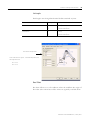
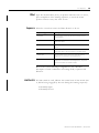
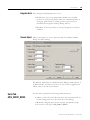
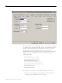
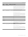
Axis Attributes
Attribute
Axis Type
Data Type Access Description
Velocity
Proportional Gain
(cont.)
AXIS_SERVO_DRIVE
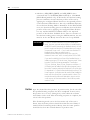
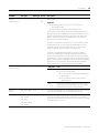
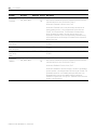
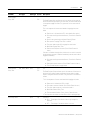
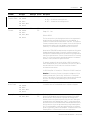
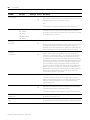
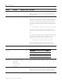
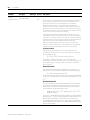
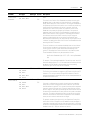
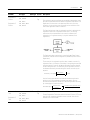
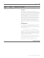
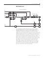
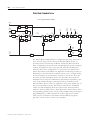
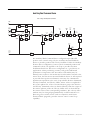
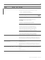
The standard RA SERCOS drive’s digital velocity loop provides damping
without the requirement for an analog tachometer. The Velocity Error is
multiplied by the Velocity Proportional Gain to produce a Torque
Command that ultimately attempts to correct for the velocity error,
creating the damping effect. Thus, increasing the Velocity Proportional
Gain results in smoother motion, enhanced acceleration, reduced
overshoot, and greater system stability. The velocity loop also allows
higher effective position loop gain values to be used, however, too much
Velocity Proportional Gain leads to high frequency instability and
resonance effects. Note that units for Velocity Proportional Gain are
identical to that of the Position Proportional Gain making it easy to
perform classic calculations to determine damping and bandwidth.
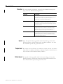
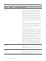
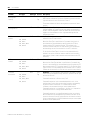
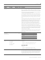
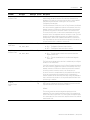
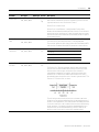
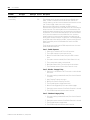
If you know the desired unity gain bandwidth of the velocity servo in
Hertz, use the following formula to calculate the corresponding P gain.
Vel P Gain = Bandwidth (Hertz) / 6.28
In general, modern velocity servo systems typically run with a unity gain
bandwidth of ~40 Hertz. The typical value for the Velocity Proportional
Gain is ~250 Sec-1.
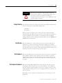
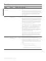
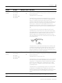
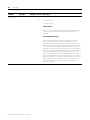
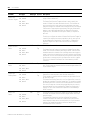
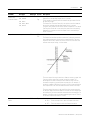
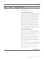
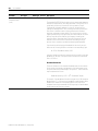
Maximum Bandwidth
There are limitations to the maximum bandwidth that can be achieved
for the velocity loop based on the dynamics of the inner torque loop of
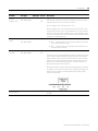
the system and the desired damping of the system, Z. These limitations
may be expressed as follows:
Bandwidth (Velocity) = 0.25 * 1/Z2 * Bandwidth (Torque)
For example, if the bandwidth of the drive’s torque loop is 100 Hz and the
damping factor, Z, is 0.8, the velocity bandwidth is approximately 40 Hz.
Based on this number the corresponding gains for the loop can be
computed. Note that the bandwidth of the torque loop includes feedback
sampling delay and filter time constant.
Publication LOGIX-UM002B-EN-P - January 2007