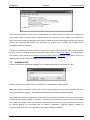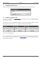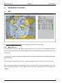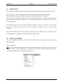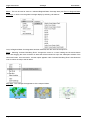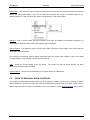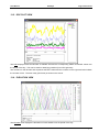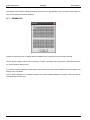
1
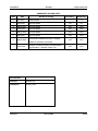
Fugro Intersite Ltd
GeoSkyII
User Manual
© Copyright 2009 Fugro Intersite Ltd
Dated: June 2009
User Manual
GeoSkyII
Fugro Intersite Ltd
AMENDMENT RECORD SHEET
Issue
Date
Reason for change
Revised by
Authorised
0
Nov 2002
Initial Release
TJ
TJ
1
Sept 2004
General Update
PK
PK
2
March 2005
General Update
CJH
RHA
3
June 2005
General Update
CJH
RHA
4
March 2006
General Update
CJH
RHA
5
April 2006
General Update
CJH
RHA
6
March 2009
JCR
RHA
7
June 2009
JCR
RHA
Converted to Standard Document Template.
Added G2 (Glonass) functionality.
Change to Scenario Dialog to include System
Type Enabled – Software release 4.01
Document No.
Filename
GeoSkyII.doc
Distribution
GeoSky Users
Revision 7
29 June 2009
Prelim
User Manual
GeoSkyII
Fugro Intersite Ltd
CONTENTS
SECTION
Page No
SECTION
CONTENTS ......................................................................................................................................................... I
1.
EXECUTIVE SUMMARY....................................................................................................................... 1
2.
INTRODUCTION ................................................................................................................................... 2
3.
REQUIREMENTS ................................................................................................................................. 3
4.
SOFTWARE INSTALLATION ............................................................................................................... 4
4.1.
4.2.
4.3.
5.
GEOSKY PROGRAM .............................................................................................................. 4
GEOSKY FILES ....................................................................................................................... 4
TO RUN GEOSKY ................................................................................................................... 4
OPERATION ......................................................................................................................................... 6
5.1.
5.2.
START-UP ............................................................................................................................... 6
TOOLBAR ................................................................................................................................ 6
6.
FILE ....................................................................................................................................................... 7
6.1.
NEW ......................................................................................................................................... 7
6.2.
OPEN ....................................................................................................................................... 7
6.3.
SAVE ........................................................................................................................................ 7
6.4.
SAVE AS .................................................................................................................................. 7
6.5.
EXIT ......................................................................................................................................... 8
7.
CONFIGURE ......................................................................................................................................... 9
7.1.
7.2.
7.3.
7.4.
7.5.
8.
ACTION ............................................................................................................................................... 13
8.1.
9.
SCENARIO............................................................................................................................... 9
SCENARIO FILE .................................................................................................................... 10
ALMANAC FILE ..................................................................................................................... 11
NETWORK DEFINITION FILE ............................................................................................... 12
DOWNLOAD GEOSKY FILES ............................................................................................... 12
INTERNET CONNECTION .................................................................................................... 13
REFERENCE STATIONS ................................................................................................................... 14
9.1.
MAP ........................................................................................................................................ 14
9.2.
MAP DISPLAY ....................................................................................................................... 14
9.3.
TEXT BLOCK ......................................................................................................................... 15
9.4.
RIGHT CLICK MENU ............................................................................................................. 15
9.5.
ZOOM TO REGIONAL BEAM COVERAGE .......................................................................... 17
Continued….
Revision 7
29 June 2009
Page i
Fugro Intersite Ltd
GeoSkyII
User Manual
CONTENTS (Continued)
SECTION ............................................................................................................................................... Page No
10.
NETWORK LIST ..................................................................................................................................18
11.
FREQUENCY LIST ..............................................................................................................................19
12.
WEBSITE .............................................................................................................................................20
13.
GPS .....................................................................................................................................................21
13.1.
13.2.
13.3.
13.4.
13.5.
13.6.
13.7.
GPS MAP................................................................................................................................21
AVAILABILITY VIEW ..............................................................................................................22
SKYPLOT DISPLAY ...............................................................................................................23
SKYTIME VIEW ......................................................................................................................24
DOP PLOT VIEW ...................................................................................................................25
ELEVATION VIEW .................................................................................................................25
DISABLE SV ...........................................................................................................................26
14.
REPORTING........................................................................................................................................27
14.1. GPS MISSION PLANNING.....................................................................................................27
14.2. REFERENCE STATION COVERAGE ...................................................................................27
15.
WINDOWS ...........................................................................................................................................29
15.1.
15.2.
15.3.
TILE ........................................................................................................................................29
CLOSE ALL ............................................................................................................................29
THE OPEN WINDOWS ..........................................................................................................29
16.
GEOSKY HELP ...................................................................................................................................30
17.
ABOUT.................................................................................................................................................31
Page ii
29 June 2009
Revision 7
User Manual
1.
GeoSkyII
Fugro Intersite Ltd
EXECUTIVE SUMMARY
Although Fugro has taken due care in the preparation of this documentation and the associated
software/hardware, no responsibility is accepted for the use or reliability of either. Due to the continuing
development nature of these systems, information in this documentation is subject to periodic updates without
notice and does not represent a commitment on the part of Fugro.
All data, graphs, video imagery used in the production of this manual are representative and are only
provided as examples. Information displayed by your use of the software/hardware may be different.
GETTING TECHNICAL SUPPORT
If you have problems that you cannot solve, bugs that you have detected, or new features that are needed to
perform things better, please give feedback to the developers, as they cannot fix things if not told about them.
•
For situations that are immediately critical, the helpdesk can be contacted by phone.
•
For situations that are not critical, write as full a description of the problem, and the occurring situations,
with a description of your hardware. Similarly for a feature request - new feature or change of current.
Send this information to the address below (email is quicker), and send a copy to your regional
manager.
Fugro Intersite Ltd
Morton Peto Road
Great Yarmouth
Norfolk
NR31 0LT
UK
Tel:
+44 (0) 1493 440320
Fax:
+44 (0) 1493 440319
Duty Phone:
+44 (0) 7976123015
Email:
[email protected]
Revision 7
29 June 2009
Page 1
Fugro Intersite Ltd
2.
GeoSkyII
User Manual
INTRODUCTION
GeoSky II is a GPS and Reference station mission planning tool.
GeoSky II is a replacement for the original DOS based GeoSky software with the addition of a significant
number of additional features, including:
Starfix Station ranges
GPS Mission planning
Automatic updating of the Almanac, via the internet
Automatic updating of the Starfix station list, via the internet
Automatic creation of reports in Microsoft Word format
The text in this manual conforms to certain conventions:
Page 2
1.
All command buttons are shown bold and bracketed with square brackets e.g. [OK],
2.
When a keyboard key is represented, it is shown bold and bracketed by greater than and lesser
than symbols e.g. <spacebar>
3.
Each dialogue has a title. When the name is in the text it is underlined e.g. Edit GPS Receiver.
4.
Direct quotations from dialogues or edit control slots are shown in normal text in quotations, e.g.
“IO Channel:”
5.
Hypertext links are shown as hyperlink
29 June 2009
Revision 7
User Manual
3.
GeoSkyII
Fugro Intersite Ltd
REQUIREMENTS
The recommended requirements for GeoSky are:
•
A PC running Windows NT, Windows 2000 or Windows XP. The minimum recommended PC is a
600 MHz Pentium III with 64 MB RAM. A graphics resolution of at least 1024 by 768 pixels is
advised in order to achieve maximum clarity of all the graphics displays.
•
For generation of reports in Microsoft Word format a copy of Microsoft Word 97 or 2000 must be
installed on the same machine.
•
A connection to the internet for downloading updates to the GPS almanac and Starfix station lists.
•
For the installation of the applications, the PC should have a CD-ROM drive. It is also possible to
download the installation from the Internet.
Revision 7
29 June 2009
Page 3
Fugro Intersite Ltd
GeoSkyII
4.
SOFTWARE INSTALLATION
4.1.
GEOSKY PROGRAM
User Manual
The GeoSky program can be installed as part of the MultiFix - GPS Suite, or from the standalone install
available on www.skyfix.com
4.2.
GEOSKY FILES
After installation and after a program run, GeoSky II will have created / stored several files in the folder
selected by the operator for the configuration file.
The core GeoSky configuration file has the extension gs2. In addition, there is an ancillary configuration. This
is the GeoSky Persistence file and has an extension GS2_PST. It is the number, type, position and contents of
windows in the application workspace at the time of a configuration save. The persistence file is also is also
saved when the program is exited.
Stored within the GeoSky installation directory is a GPS almanac, with the extension XAL.
The default
almanac has the filename Default.xal. This is automatically updated, via the Internet, when prompted by the
user.
Alternatively, an almanac file can be selected by the user, in which case the Default.xal file is not used.
4.3.
TO RUN GEOSKY
GeoSky can be opened various ways.
1. Use “Start” \ “Programs” \ “GeoSky II” and click “GeoSky II”.
2. Use Windows Explorer to display the contents of the folder containing the GeoSky
program files and then double-click the “GeoSky II” application icon.
3. Drag the “GeoSky II” application icon from the Windows Explorer window onto the
desktop to create a shortcut. Thereafter double-click the shortcut.
On start-up GeoSky will check the almanac file. If the almanac is more than 4 days old GeoSky will prompt
the user to update the almanac. This can be completed automatically via the Internet. However, the user will
first be prompted to activate GeoSky's internet connection, via the "Action" menu.
Right-mouse clicking most windows allows the user to customise the display. Where that customisation is
specific to the view window it will be mentioned in the relevant section dealing with that window. However,
several windows share the same two facilities, to “Copy” and to “Save As…”
Page 4
29 June 2009
Revision 7
User Manual
GeoSkyII
Fugro Intersite Ltd
“Copy” places a bitmap of the window onto the clipboard, from whence it can be pasted into another
application.
“Save As Bitmap” allows a bitmap file of the view window to be saved. By default the file will be placed in the
folder that contains the GeoSky configuration file. The bitmap files are saved simply as .bmp images.
In common with many Windows programs, GeoSky allows display windows to be moved outside the area
displayed by the monitor. The application workspace automatically extends and scroll bars are provided. The
scroll bars allow the display area to move around the extended application workspace. There is no limit on the
number of windows of any type that can be open in the application workspace. Multiple copies of the same
window type can be open. Indeed it will be seen that once a window is open some types of window allow
further selection of the data that is to appear in them.
Most windows can be resized by clicking and dragging corners or sides. Some windows that contain text will
wrap the text message into the available space, while other windows containing text will simply be cropped as
the window size reduces.
Some windows containing graphical information will resize to a minimum and will then either crop the
information or will introduce scroll bars.
Revision 7
29 June 2009
Page 5
Fugro Intersite Ltd
5.
OPERATION
5.1.
START-UP
GeoSkyII
User Manual
On start up GeoSky will first open the Reference Station map display. The software will then check the current
Almanac age. If the stored Almanac is more than 4 days old a warning box will be displayed, asking if you
wish to download the latest GPS almanac via the internet.
Selecting Yes will download the latest Almanac and station list from the Fugro Web server, providing that the
GeoSky's internet connection has been activated via the "Action" menu.
GeoSky will also check for recent Positioning news updates on the Fugro web page.
5.2.
TOOLBAR
The toolbar menu allows the user quick access to the most commonly used displays. The buttons include:
Open configuration
Save Configuration
Map – Opens a window containing the SkyFix station map.
Station List – Opens the station list display
Web site – Opens your default web browser and takes you to the Thales GeoSolutions precise
positioning Website.
GPS Map – Displays the animated GPS map
Availability – Opens the GPS availability display
SkyPlot View - Opens the SkyPlot view display
Time View- Opens the animated SkyTime view.
DOP view –Opens the DOP display window
Elevation – Opens the elevation display window.
SV disable – Opens the SV disable dialogue.
See below for details of each display.
Page 6
29 June 2009
Revision 7
User Manual
6.
FILE
6.1.
NEW
GeoSkyII
Fugro Intersite Ltd
Select this option to start a new GeoSky configuration.
Note: starting a new configuration will close the existing configuration. A warning dialogue will warn you of
this and request confirmation. If the configuration has not already been saved the dialogue will offer the option
to do so first.
6.2.
OPEN
If the program has been run by double-clicking the GeoSky icon or by using “Start” \ “Programs” \ “GeoSky II”
and clicking “GeoSky”, the program does not know the configuration to open. Assuming a previously prepared
configuration exists, use this facility to select it.
The configuration files have program name and version identifiers in a file header.
They also have a
configuration file version number. The program will not allow configuration files to be opened that are not
compatible with the version of GeoSky that is currently being run. However if the configuration file version is
the same they can be used even though created by a different program version.
File open can also be accomplished using the button.
(Whether “Open as read-only” is ticked or not, does not make any difference).
6.3.
SAVE
A configuration is not automatically saved as changes are made, therefore use this facility to update the
configuration file to the current status. If the set up is being undertaken for the first time and the configuration
does not have an identity, the use of “File” \ “Save” will call up the Save As dialogue. That dialogue requires a
name to be entered for the GeoSky files. Once a configuration has been named, use of “File” \ “Save”
performs the save without calling up the Save As dialogue.
The name of the current configuration file appears in the application workspace title bar. If configuration
changes are made that have not been saved, that file name has an * appended to it. After a File \Save the * is
removed.
File saving can also be accomplished using the button.
6.4.
SAVE AS
If the current configuration is to be saved but not at the expense of overwriting the existing configuration files,
use the “File” \ ”Save As…” option. This creates new GeoSky files and leaves the previous files as they were.
The program immediately commences to use the new files as the current configuration files.
Revision 7
29 June 2009
Page 7
Fugro Intersite Ltd
GeoSkyII
User Manual
The Save As dialogue requires the operator to enter a name for the new configuration file. If an existing file
name is entered, the program will overwrite the existing files.
6.5.
EXIT
This exit route is immediate if no configuration file is loaded.
Confirmation is required if a configuration file is in use. The user will be prompted to save the configuration if
they have not already done so.
If the program is exited using the button when the current configuration has not been saved, a dialogue is
presented asking whether to save the configuration prior to exit or whether to cancel the exit. If there have
been no configuration changes since the file was last saved the user will be prompted to confirm the exit
command.
Page 8
29 June 2009
Revision 7
User Manual
7.
CONFIGURE
7.1.
SCENARIO
GeoSkyII
Fugro Intersite Ltd
The Scenario configuration allows the operator to define each of the parameters used for planning.
The “Name” is only used for reporting purposes
The “Date” is used for the GPS Mission planning. All displays of GPS availability will be for the date selected.
The date can be entered in a number of formats, in full, abbreviated or as ddmmyy.
The “Location” parameters can be manually entered. Both the “Latitude” and “Longitude” edit controls allow a
flexible form of data entry. The N/S or E/W can be at the start or end of the value. Space, comma or colon
can separate the degrees, minutes and seconds. The Latitude and Longitude will be automatically updated
when the location marker is moved on the map displays, see Reference Station Network Map for more details.
The “SV Elevation mask” will set the minimum elevation at which any GPS satellite is considered useable.
The “Beam Elevation mask” will set the minimum elevation at which any Starfix delivery satellite is considered
useable.
The “Max Range to Station” is the maximum distance that a station can from the users location to be included
in the selection for display and reporting. Typical maximum operating range is 2000km.
The “System Type Enable” controls what satellite systems are shown in the various GeoSky Views
Revision 7
29 June 2009
Page 9
Fugro Intersite Ltd
7.2.
GeoSkyII
User Manual
SCENARIO FILE
This option allows the user to import the Scenario information from file.
In order to do this, firstly the user must "Activate" this option, and then browse to the relevant scenario file.
The format of the Scenario File is XML and shown by two examples below, both being equally valid but
showing different ways of storing the data fields. The tag names (e.g. "scenario", "name", "latitude") must be
spelt correctly, however, they are not case sensitive. The tags correspond directly to the information held
within the Scenario Dialog.
The file does not have to contain every tag shown, only the "scenario" tag is necessary, the user can pick and
choose from "name", "latitude", "longitude", "mask", "beamMask" and "range", with those that are present
overriding the information contained in the Scenario Dialog.
Page 10
29 June 2009
Revision 7
User Manual
GeoSkyII
Fugro Intersite Ltd
Once GeoSky has taken a scenario from the selected file, it will then continue to monitor this file. GeoSky will
automatically update its scenario data if it detects that the scenario file has been modified. This means that a
user could have a positioning application that is able to update the scenario file position and also have GeoSky
running and monitoring the scenario file. Whenever the scenario file is updated the changes will be
immediately reflected in GeoSky.
It should be noted that if the user chooses to override the "Latitude" and "Longitude" values using a scenario
file, they will then not be able to modify these values further, either via the Scenario Dialog, or by dragging the
User Position Cursor shown by the Reference Station Network Map or GPS Map. These values will only be
updated within GeoSky if they are updated within the scenario file itself.
7.3.
ALMANAC FILE
If there is no access to the Internet available, an up to date almanac file can be loaded from file.
GeoSky will take in an almanac file from a MultiFix (Ver 1.26 onwards) configuration file.
Note- files loaded from MultiFix version 1.29 or earlier will not display the correct date of almanac file in the
GPS mission planning windows. The date the file was loaded into GeoSky is displayed instead.
Once GeoSky has taken an almanac from a file selected in this manner, it will then continue to monitor this file.
GeoSky will automatically update it's almanac if it detects that the selected almanac file has been modified.
This means, for example, that a user could have both MultiFix and GeoSky running, with GeoSky monitoring
the specific almanac file associated with the MultiFix configuration. Whenever MultiFix updates its
configuration almanac file, the changes will be immediately reflected in GeoSky.
Revision 7
29 June 2009
Page 11
Fugro Intersite Ltd
7.4.
GeoSkyII
User Manual
NETWORK DEFINITION FILE
If there is no access to the Internet available, an up to date Station list file can be loaded from Disk.
7.5.
DOWNLOAD GEOSKY FILES
This option is only available if the Internet Connection has been enabled. See Item 8.1 Internet Connection
before selecting this option.
Once selected a connection is established and GeoSky II will download any updates available for: Almanac,
Network Definitions and Footprint files. Once complete the following should be displayed:
Click on OK to close dialog boxes.
Note: - On start-up GeoSky will check the age of the current almanac and offer to download the latest version
if the current almanac is more than 5 days old. If the Internet Connection option isn't enabled, GeoSky will first
prompt the user to enable this.
Page 12
29 June 2009
Revision 7
User Manual
8.
ACTION
8.1.
INTERNET CONNECTION
GeoSkyII
Fugro Intersite Ltd
This option either enables or disables the GeoSky internet connection. When running GeoSky for the first time
it is automatically set to disabled, to prevent hang ups for offline users. The user is prompted to enable this
setting if an almanac download is recommended.
Revision 7
29 June 2009
Page 13
Fugro Intersite Ltd
9.
REFERENCE STATIONS
9.1.
MAP
GeoSkyII
User Manual
The Reference Station Network Map is the key display to the Mission planning facility.
9.2.
MAP DISPLAY
The users entered location is displayed on the map as a red dot. This red dot can be dragged and dropped
around the map using the mouse; the User location will then be automatically updated throughout the current
configuration.
It is possible to view only the regional coverage area of each beam by selecting the appropriate beam from the
Right Click Menu.
All Starfix stations are displayed on the map. Stations highlighted in blue are within the user-defined range.
Each visible Starfix satellite is also displayed, and the associated beam coverage is highlighted on the map.
Each individual Starfix beam is colour coded and the same colour associations are used throughout the
software.
Page 14
29 June 2009
Revision 7
User Manual
9.3.
GeoSkyII
Fugro Intersite Ltd
TEXT BLOCK
The text block on the right hand side of the map includes the same information that is displayed on the map.
The current “User Location” is displayed, in Lat and Long, with the currently defined station range.
The second section contains information relating to all “Visible Beams”, for the user location.
The full name of each beam is listed with the associated colour definition. In addition, the elevation and
azimuth to the delivery satellite is displayed. This is to aid in setting up a directional reception dish, such as
the Fugro MiniDome.
The third section lists each “Station” that lies within the defined user range. Each station is listed by name
along with ID numbers range to station and whether the station is enabled for Starfix+, HP, and Glonass
corrections.
The final column lists which beams the station is available upon. Beam definition is by Colour blocks, using
the associated colours defined in the table “Visible Beam” section above.
9.4.
RIGHT CLICK MENU
The main map display can be configured in a number of different ways via a right click of the mouse on the
main map display.
There are 8 options:
Layer - The XML file containing the beam and reference station information stores this as a "layer", with the file
and GeoSky able to handle multiple layers. This option allows the user to select the desire layer, however,
currently only a Starfix layer is contained within the XML file.
Revision 7
29 June 2009
Page 15
Fugro Intersite Ltd
GeoSkyII
User Manual
Beam - This can be used to zoom to a selected Regional Beam Coverage area (see Zoom to Regional Beam
Coverage), or back out to the global coverage display by selecting “All Stations”.
Only if a Regional Beam Coverage area has been selected, then the user has the option to...
Zoom - Selecting "Activate Click/Drag Zoom" changes the cursor to a cross. Holding the left mouse button
down and dragging the cursor encloses an area that will be zoomed into upon the subsequent release of the
left mouse button. Once zoomed in, a further option appears under "Activate Click/Drag Zoom" that allows the
user to restore the map to the full beam.
Map Style - This changes the appearance of the map as follows.
“Normal”
Page 16
“Textured”
29 June 2009
“Lined”
Revision 7
User Manual
GeoSkyII
Fugro Intersite Ltd
Rotate Map – This allows the user to rotate the projected map to prevent any overlap when working near the
edge of the current map display. The user can rotate the map either left or right in incremental steps of 45°.
Selecting Centre on User will centre the current map projection on the users location.
Mercator - This is used to select the map projection to be used, the default is the Mercator projection, by
deselecting the Mercator option a Non-orthomorphic map is displayed.
Select Location – This allows the user to set the user location (Scenario) to the location of the cursor when the
right hand button was clicked.
The following two alternate options appear depending upon the current beam selection. Only if the global
coverage display is selected then the user has the option to...
Copy - Saves the current display to the clip board.
The image can then be placed directly into other
documents using the Paste command.
Save As Bitmap – Allows the current Bitmaps to be saved directly as a Bitmap file.
9.5.
ZOOM TO REGIONAL BEAM COVERAGE
The Reference Station Network Map display can be configured to display only the area covered by a specific
Starfix satellite. It is possible to jump to any of the available beams using the right click "Beam” option. Once a
specific beam has been selected, it is possible to then zoom further in, via the Right Click Menu "Zoom" option.
Revision 7
29 June 2009
Page 17
Fugro Intersite Ltd
10.
GeoSkyII
User Manual
NETWORK LIST
The station information is stored in an XML format database. The Network List window allows the user to view
the XML file directly.
This file can be updated automatically by selecting Download Network Definitions from the configuration menu.
It is also possible to edit the XML file, using a standard text editor. The local configuration file is stored in the
GeoSky II installation directory with the file name fugronet.sfx.
Page 18
29 June 2009
Revision 7
User Manual
11.
GeoSkyII
Fugro Intersite Ltd
FREQUENCY LIST
The Frequency List calls up the Beam Information list.
This includes all the information required for setting up a decoder, including the frequency, data rate and LOS
setting.
Note -the LOS setting is made on the antenna, not the decoder unit.
Revision 7
29 June 2009
Page 19
Fugro Intersite Ltd
12.
GeoSkyII
User Manual
WEBSITE
Clicking on the Website option will take you directly to the Fugro Precise Positioning Website, if an Internet
connection is available. http://www.skyfix.com
Page 20
29 June 2009
Revision 7
User Manual
13.
GeoSkyII
Fugro Intersite Ltd
GPS
13.1. GPS MAP
The GPS Map display shows the animated ground track of all GPS satellites. The SVs are highlighted as
soon as they become visible to the users location. If they are visible but below the elevation mask then the
PRN number will be displayed in red.
The animation will continuously run for the full 24-hour period of the selected day. At midnight, the animation
reverts to the start of the day and runs again.
The text box to the right of the screen includes the elevation and azimuth of all visible satellites. Again, they
are displayed in red if below the elevation mask
It is possible to stop the animation at any time by pressing the <spacebar>. It is then possible to move the
animation backward and forward in fifteen minute steps by using the <+> and < - > keys.
The right click option allows the selection of different map displays as per the SkyFix map.
Revision 7
29 June 2009
Page 21
Fugro Intersite Ltd
GeoSkyII
User Manual
13.2. AVAILABILITY VIEW
The Availability plot shows the availability of all satellites for the selected day.
Each PRN number is listed along the left and right hand sides of the display, with the time of day (GPS time)
shown on the X-axis.
The useable period for each satellite is shown as a green bar. Disabled satellites are shown in red.
The text at the bottom of the display includes the date of the current GPS almanac, the user’s location and the
date for which the display is valid.
Page 22
29 June 2009
Revision 7
User Manual
GeoSkyII
Fugro Intersite Ltd
13.3. SKYPLOT DISPLAY
The SkyPlot display shows the full path of all satellites during the day.
This display is useful to identify the GPS blind spot caused by the non-polar orbits of the GPS satellites.
Revision 7
29 June 2009
Page 23
Fugro Intersite Ltd
GeoSkyII
User Manual
13.4. SKYTIME VIEW
The SkyTime Display animates the path of the satellites over the period of the day, relative to the user’s
location.
The animation can be shifted to any part of the day by using the mouse to move the indicator line on the
progress bar at the bottom of the screen.
Start and stop times for the animation can be set by right clicking the progress bar and setting the start and
stop times.
Page 24
29 June 2009
Revision 7
User Manual
GeoSkyII
Fugro Intersite Ltd
13.5. DOP PLOT VIEW
The DOP displays shows the Number of available SVs and the corresponding PDOP and HDOP values over
the period of the day. This can be used for identifying periods of poor GPS geometry.
The numbers on the left hand axis represent the DOP values and the numbers on the right hand axis indicate
the number of SVs. The time of day (GPS time) is shown on the X-axis.
13.6. ELEVATION VIEW
The Elevation view displays the elevations of each satellite over the period of the day.
Revision 7
29 June 2009
Page 25
Fugro Intersite Ltd
GeoSkyII
User Manual
This display can be used to identify periods where there are no high elevation SVs, forcing the GPS solution to
rely on less stable low elevation satellites.
13.7. DISABLE SV
Disable SV allows the user to disable selected Satellites for the purposes of GPS mission planning.
The SV Status dialogue shows a list of all the SV numbers. Numbers that are greyed out indicate that there is
no current almanac data for them.
If a number is clicked then that number will be shown with a red cross and the satellite will be excluded from all
displays until re-enabled.
The SV Status dialogue is a modeless dialogue and unlike standard dialogues, program control can still be
exercised while it stays open.
Page 26
29 June 2009
Revision 7
User Manual
14.
GeoSkyII
Fugro Intersite Ltd
REPORTING
GeoSky will automatically generate reports for both GPS mission planning and SkyFix station availability.
Microsoft Word 2000 or Word 97 must be installed in order to generate a report. Reporting will not work
correctly under Word 95 or earlier
14.1. GPS MISSION PLANNING
Upon selecting a “GPS Mission Planning” report, a save as dialogue will be presented to the user. The default
file name will be based on the date for which the report is to be generated.
The report will be generated for whichever day and user location has been defined under the configuration
Scenario.
The GPS mission planning report contains plots of satellite availability, HDOP, PDOP, number of satellites,
elevation of satellites and a SkyPlot of satellite paths.
14.2. REFERENCE STATION COVERAGE
The Reference Station Coverage Report is generated in the same way as the GPS Mission Planning report.
The Reference Station Coverage Report includes maps for each visible beam and a table containing details of
each visible station, including:
Name
ID
Range
Starfix Plus availability
Starfix HP availability
Glonass availability
Each beam is also listed providing details of the elevation and azimuth, relative to the user’s location and the
frequency of the SkyFix transmission.
Revision 7
29 June 2009
Page 27
Fugro Intersite Ltd
GeoSkyII
User Manual
Selected Beams Locations:
Layer :
Beam Name
Starfix
Elev
Azi
IF(MHz)
RF(MHz)
Atlantic Ocean Region (East)
27
200
75.090
1535.0900
Atlantic Ocean Region (West)
11
241
75.098
1535.0975
Atlantic Ocean Region (West) H
11
241
75.185
1535.1850
EA-Sat
25
151
75.153
1535.1525
AF-Sat
25
151
75.140
1535.0800
Atlantic Ocean Region (East) H
27
200
75.125
1535.1250
Station Ranges
Layers:
Page 28
Station Name:
Leidschendam
Aberdeen
Shannon
Rogaland
Toulouse-New
Toulouse
Torshavn
Vienna
Trondheim
Brønnøysund
Faro
ID:
521
571
530
580
434
431
620
480
632
650
371
29 June 2009
Range:
219
555
688
751
1003
1005
1154
1190
1317
1557
1878
Sfx+:
No
Yes
No
No
No
Yes
Yes
No
Yes
Yes
Yes
HP:
Yes
Yes
Yes
Yes
Yes
Yes
Yes
Yes
Yes
Yes
Yes
Glonass:
No
Yes
No
No
Yes
No
No
No
Yes
No
No
Revision 7
User Manual
15.
GeoSkyII
Fugro Intersite Ltd
WINDOWS
This is a standard Windows style menu. The listing will change depending on the number and types of
windows that are open at any one time.
15.1. TILE
The tile command causes the application workspace to be reduced to the display area. The windows that are
not minimised are fitted into the display area and the minimised windows are neatly stacked along the bottom
of the screen.
15.2. CLOSE ALL
The close all command does just that. All the windows irrespective of their status will be closed. As there is
no confirmation required, be careful not to use it in error.
15.3. THE OPEN WINDOWS
The “Window” drop down will also list all the windows currently open. Windows can be overlain one on top of
another and it can be difficult to locate an obscured window. Clicking the window in the list causes the focus
to shift to that window, the title bar is highlighted and it will come on top of all the other windows. If there is an
extended application workspace and the selected window is off screen, while it will be the window with the
focus the display area will not move to show the window.
If there are more than 9 windows open the bottom line will be “More Windows…” If that is selected a dialogue
is opened listing all the windows. Highlight one of them and close the dialogue.
Revision 7
29 June 2009
Page 29
Fugro Intersite Ltd
16.
GeoSkyII
User Manual
GEOSKY HELP
Opens the online help file.
Page 30
29 June 2009
Revision 7
User Manual
17.
GeoSkyII
Fugro Intersite Ltd
ABOUT
This provides the version number and release date
Revision 7
29 June 2009
Page 31