1
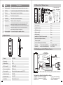
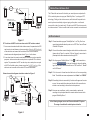
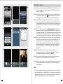
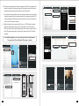
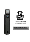
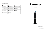
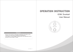
Statement
* If there is any doubt or disputable regarding information in this
manual, you can call our company for clarification. ...................
* In all cases, for more details, please refer to the electronic user’s
manual on the included. Thanks.
MC-1067(A-2)
1
Safety Instructions
※ Read these instructions and keep them in a safe place for future reference.
※ Please refer all work related to the installation of this product to qualified
service personnel or system technician.
※ Do not operate the appliance beyond its specified temperature, humidity or
power source ratings.
※ Securely install the devices on vertical surfaces(solid walls/doors)not prone
to vibration or impact.
※ Install the devices away from heat sources such as radiators, heat registers
and stoves.
※ Installation of the terminal near consumer electronics devices, e.g. stereo
receiver/amplifiers and televisions, is permitted as long as the air surrounding
the terminal does not exceed the above mentioned temperature range.
※ Handle the appliance with care. Do not strike or shake, as this may damage
the device.
※ The doorbell/camera units should be fitted with an approved weather shield
if the chosen position is in direct sunlight, or in contact with rain, snow or
irrigation sprinkler systems.
※ Do not use strong or abrasive detergents when cleaning the appliance body.
When the dirt is hard to remove, use a mild detergent and wipe gently.
※ Do not overload outlets and extension cords as this may result in a risk of fire
or electric shock. Distributing, copying, disassembling, reverse compiling,
reverse engineering, and also exporting in violation of export laws of the
software provided with this product, is expressly prohibited.
2
Description Of IP Outdoor camera
2.1 Feature (Please take actual model as quasi)
8
7
1
No.
Name
Descriptions
1
Weather shield
Affix and protect outdoor camera from rain or snow.
2
IR LEDs
Provides illumination with IR LEDs for better visibility.
3
Camera
Capture image to transmit to display
4
Speaker
Sound from smart-phone
5
Call button
Visitor call for intercommunication
6
Microphone
Transmit voice to smart-phone
System port
For the models with wired function, connect the doorbell to external
switching power supply(DC 12V), ethernet cable and door lock.
For the models with wireless function, connect the doorbell to external
switching power supply(DC 12V), door lock and indoor antenna or
outdoor antenna, and antenna can be optional.
7
8
Volume regulator To be used to adjust the speaker volume.
2.2 Specifications
2.3 Fitting of the IP Outdoor Camera
Antenna(optional)
Outdoor
antenna
Indoor antenna
(optional)
(optional)
or
Outdoor camera
1pcs
Plastic anchor
2pcs
Installation screws
2pcs
Affixation screws
3pcs
Weather shield
1pcs
Angle bracket
1pcs
Installation CD (with full manual and
1pcs
android mobile phone software)
This quick guide
1pcs
External Switching Power Adapter
1pcs
Antenna
(optional)
or
Indoor antenna(optional)
outdoor antenna(optional)
1pcs (6dBi or 3dBi)
1pcs (10dBi)
2.4 Wiring Diagram of the IP Outdoor Camera
Antenna(optional)
To Internet
OG
+
OG&WH
Camera
2
External switching power supply
DC 12V
1/4 CMOS
Network Cable
o
View angle
60
Definiton(Hor.)
1.0M
GN&WH
GN
Antenna connector
1.GN&WH
(optional)
o
LEDs for night
IR LEDs(60 )
Power consumption
300mA max.
Power supplier
External switching power supply DC12V.
Network Interface
10/100M
Operation temp.
-40~+50℃
Installation
Surface/flush mount
b
2.GN
3.OG&WH
4.OG
5.RD:DC 12V
6.BK:GND
7.BN
8.BN
Note: GN--Green, WH--White, OG--Orange, RD--Red, BK--Black, BN--Brown.
The terminal is defined functionality as below:
1.GN&WH: To network wire GN&WH
3.OG&WH: To network wire OG&WH
5.RD: DC 12V
6.BK: GND
2.GN: To network wire GN
4.OG: To network wire OG
7/8.BN: To door lock.
3
In the standard delivery the system support locks with Normally Open(N.O.) door
unlocking method. It means that in the normal state the dry contact(marked as )
is opened, so the lock is kept under constant closed state. If the unlocking button
is pressed and the dry contact is changed to closed, then the lock is released.
If the speaker volume is too low, how to increase it?
At the backside of outdoor unit, you can find out a regulator
(Marked as b )
which is used to adjust the speaker volume, turn the regulator with the screwdriver
to decrease/increase the speaker volume.
2.5 Installation process of Outdoor Units
Please follow these steps as reference:
1.Select the most suitable position where the outdoor camera is located at user’s
eye level, then drill 2 holes according the weather shield, embed 2 plastic
anchors into the holes.
2.Use a screwdriver to affix the weather shield with the installation screws.
3.Drag the connection cable through the hatch at the bottom side.
4.Embed the outdoor unit into the weather shield and affix with the supplied screws.
* Avoid installation of the device near strong radiation e.g. AC motor and lift.
* Maintenance should be complied with qualified technician.
3
Device Connect--Through wired network or wireless network(optional)
* Avoid hard shake, beating and collision, otherwise the internal exact components
maybe be damaged.
* Do not expose the outdoor camera under strong light or sunshine.
* Do not install the outdoor camera in the environment e.g. direct sunlight,
contact rain, High temperature, high humidity, full of dust and chemistry
corrosive.
* Select the most suitable position where the camera is located at user’s eye level.
* Switch off power supply before installation.
* Keep more than 30cm away from AC power supply to avoid external interference.
4
* Keep it away from the water and magnetic field.
A. User can connect the outdoor camera through network cable,
operation steps:
1. Connect the network cable to the outdoor camera according to section
2.4 wiring diagram of the IP outdoor camera.
2. Connect the power adapter to the electrical outlet of the outdoor camera
and power on.
3. Wait for a while until hearing a beep, this time the outdoor camera starts
completely.
Network connection diagram through wired network as Figure 1.
5
3G/WIFI
4
Internet
Modem
Mobile Phone Software Visit
This IP doorbell can transmit live feed to your smart-phones and pads with
To WAN
IOS or android system via a program “MobileEyeDoor+”, and support P2P
IOS/Android
technology. Calling on the outdoor camera, notification will be pushed onto
Router
AC/DC power lock
(not Included) (not Included)
master’s phone immediately, ringtone ringing on the phone, confirm and
Reset
WAN
LAN
To LAN To LAN
access to the video live view directly. The device with WIFI function can work
in wireless network. The device with wired function can work in wired network.
PC
DOOR
A. Wired network
Figure 1
Step 1. Please download a program “MobileEyeDoor+” via “Play Store” on a
B. The device with WIFI function can also work in WIFI wireless network.
1. If user connects a network cable to the outdoor camera, the parameters for WIFI
can be set up via web browser, please see section Network--WIFI(optional)
of the electronic use’s manual on the included CD for more information,
network connection diagram please refer to Figure 1 on the above.
2. If user doesn’t want to connect a wired cable to the device, and user needs to
prepare a wireless router and a smart-phone or a pad with IOS or Android
system. The parameters for WIFI can be set up via a smart-phone or a pad
with IOS or Android system, please see section Soft AP function of the
electronic user’s manual on the included CD for more information.
(please refer to Figure 1 on section 3. Device Connect), connect user’s
phone/pad to the same wireless router through WIFI.
Step 3. Run the program “MobileEyeDoor+”. Click “
” to add a new device,
first click “
” to the next interface to choose the adding
type, there are three methods to add device: “QR Code Scan”, “Manual”
and “LAN Search”.
fields. The default user name and password are “Admin” and “888888".
Internet
To WAN
Step 5. After adding the device successfully, the device will appear on the main
WIFI(LAN)
Modem
LAN
Router
Antenna
(optional)
IOS/Android
screen. User can enable the alarm push function of the current device
whether or not according to his own’s actual requirement.
2
Reset
WAN
3
Step 6. Now user can surveillance, unlock, communication, capture and
WIFI(LAN)
WIFI(LAN)
AC/DC power lock
(not Included) (not Included)
PC
Step 2. Connect the outdoor camera through a wired cable to a wireless router
Step 4. Fill in the correct information about the device in the corresponding
Network connection diagram via wireless network as Figure 2.
3G/WIFI
smart-phone/pad with android system or via “APP Store” on an iPhone/
iPad with IOS system.
1
recording on his phone/pad about the remote outdoor camera via the
program “MobileEyeDoor+”.
AP mode
WIFI
(LAN)
Antenna connector
(optional)
IOS/Android
In the following diagram, we use an iPhone mobile with IOS system.
The usage of a mobile with android system is similar.
DOOR
Figure 2
6
7
B. Wireless network
Step 1. Please download a program “MobileEyeDoor+” via “Play Store” on a
smart-phone/pad with android system or via “APP Store” on an iPone/
iPad with IOS system.
Step 2. Turn WLAN function on of user’s phone, then click the “MobileEyeDoor+”
icon to run the program, click “
” to select adding mode, here must
select “
” to the next interface to add wireless device.
Step 3. In standby mode, long-press the “Call” button on the outdoor camera,
don’t loosen the button until hearing a beep, this means the device will
reboot automatically and go into the AP mode. Wait for a moment, when
hearing another beep it means the device starts successfully and goes
into AP mode.
Step 4. On “WIFI setting” interface, click “
” to enter WLAN
interface of user’s phone to see available networks, and UID number of
the outdoor camera(the UID is attached to the machine) will be shown on
the available networks list. Select it and connected successfully means
the mobile will be connected to the indoor unit directly(shown as follows).
Step 5. Return to the “WIFI setting” interface and go to the next step. Available
wireless routers will be shown on the list. Choose one and click it, if the
wireless password of the wireless router is enabled, it will pop-up a
window to enter the password of the wireless router, input the correct
password and setting ok, the indoor device will reboot automatically, it
will be connected to the wireless router after starting when hearing a
beep again.
IPDoor
2014-07-25 10:30:32
Step 6. Click “Next Step” to add a new indoor device, fill in the correct
information about the device in the corresponding fields. The default
user name and password are “Admin” and “888888”.
Step 7. Return to the WLAN settings on the mobile and choose the wireless
router which the outdoor camera has been connected to.
Step 8. Now user can surveillance, unlock, communication, capture and recording
on his phone/pad about the remote outdoor camera via the program
“MobileEyeDoor+”.
Note:
1). If the device has went into AP mode, but the wireless function of the device
hasn’t been activation via “MobileEyeDoor+” on the phone or user doesn’t do
any operate about the device, after 10 minutes the device will automatically
exit AP mode and returns to the previous connection mode.
8
9
2). When the device went into AP mode, long-press the “Talk” button again, don’t
loosen the button until hearing a beep, this means the device will reboot
automatically and will return to the previous connection mode.
3). If users want to connect the device via wireless network, when the device
restarts automatically after completing set of the parameters about WIFI,
please unplug the Ethernet cable connected to the device, otherwise the
device will run via wired network.
4). When the indoor device goes into AP mode, on “WIFI Setting” interface,
the phone with android system can be connected to the indoor device
WIFI successfully automatically please wait for a moment, and the phone
with IOS system user needs to connect the indoor device WIFI function
manually.
In the following diagram, we use a smart-phone with android system.
The usage of an iPhone/iPad with IOS system is similar.
IPDoor
10
20 14-04-24 10:20 :30
11
C. Alarm push function
To access the interface about the parameters of one device, there is an option
“video push” or “Alarm Setting” for alarm push function. When select “On” or
“Open”, it indicates that the alarm push function of the current device is enabled.
To enable alarm push function, users need to make sure the outdoor camera and
the mobile phone are both connected to internet.
Note:
1) The alarm push function can be effective, and the device must be added by UID
type.
2) When the option “video push” or “Alarm Setting” on the mobile software interface
is set to “On” or “Open”, someone press the call button on the outdoor camera, the
notification message will be pushed onto the master’s phone(shown as below).
And users can click the alarm list to access to the video live view of the channel
directly or access to the video live view to unlock for the outdoor camera.
For more details, please refer to the electronic user’s manual on the included CD.
3) For the phone with iOS system, please go into “Settings->Notification Center”
on you phone, click on “MobileEyeDoor+” and make sure you have “Badge APP
Icon, Sounds, Shown in Notification Center” enabled. Also make sure you have
“Shown on Lock Screen” enabled.
12
13