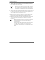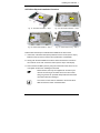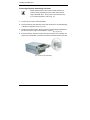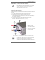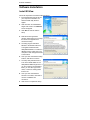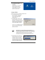
1
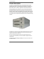
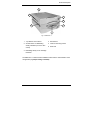
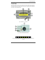
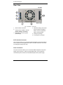
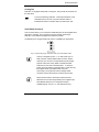
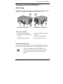
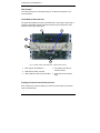
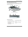
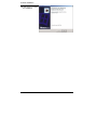
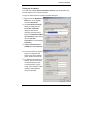
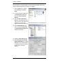
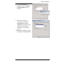
Contents
Contents
Introduction.......................................................................................................... 4
Symbols used in this Manual ................................................................................. 5
Important Instructions......................................................................................... 6
Note on the Warranty............................................................................................. 6
Exclusion of Accident Liability Obligation............................................................... 6
Liability Limitation / Exemption from the Warranty Obligation ................................ 6
Safety Instructions .............................................................................................. 7
Electrostatic Discharge (ESD) ............................................................................... 8
Grounding Methods........................................................................................... 8
FCC Statement ...................................................................................................... 9
Electromagnetic Compatibility................................................................................ 9
Scope of Delivery............................................................................................... 10
Computer System Requirements......................................................................... 10
What Else You Need ........................................................................................... 11
Type Labels and Product Identification................................................................ 11
Introduction to RAID Level ............................................................................... 12
RAID 1 ................................................................................................................. 12
Product Description .......................................................................................... 14
Features .............................................................................................................. 16
Hard Drive Hot Swapping for RAID 1 Configuration ........................................ 16
Automatic Drive Rebuilding for RAID 1 Array.................................................. 16
RAID Failure audible Alarm............................................................................. 16
Front View ........................................................................................................... 17
Disk Activity LED-Indicators ............................................................................ 18
Hard Disk Status / Rebuild Indicators.............................................................. 19
Rebuilding Activity / Error Message Indicators ................................................ 20
Drive Carrier Lock ........................................................................................... 21
Rear View ............................................................................................................ 22
SATA Interface Connector .............................................................................. 22
Power Connectors........................................................................................... 22
Cooling Fan..................................................................................................... 23
Serial RS232 Connector.................................................................................. 23
Jumper Pins .................................................................................................... 24
KISS-Stor 1 – User’s Manual
1
Contents
Components of the KISS-Stor 1........................................................................25
Drives Cage .........................................................................................................25
Holes for Mounting Screws..............................................................................25
Rail Channel ....................................................................................................26
Guide Ribs for Drive Carriers...........................................................................26
Docking Connectors for the Drive Carriers ......................................................26
SATA Removable Drive Carrier ...........................................................................27
Serial ATA and Power Connector ....................................................................28
Frame for Drive Mounting ................................................................................28
Elongated Holes for HDD Mounting.................................................................28
Docking Connector of the Drive Carrier ...........................................................28
Installing the KISS-Stor 1 ..................................................................................29
KISS-Stor 1 Physical Installation Procedure ........................................................29
SATA Drive Physical Installation Procedure ....................................................31
Drives Cage Physical Assembling Procedure..................................................32
KISS-Stor 1 Connection Procedure......................................................................33
Serial ATA Cable Connection ..........................................................................33
Power Source Connection ...............................................................................34
Serial 3-Pin Cable Connection for RAID Monitoring ........................................34
Removing / Replacing a Drive...........................................................................35
Swapping Drives ..................................................................................................35
What if a Disk fails?..............................................................................................35
What when a RAID fails? .....................................................................................35
Starting Up..........................................................................................................36
Prerequisite ..........................................................................................................36
Create a RAID 1 Array.....................................................................................36
KSView Management Software .........................................................................38
Supported Operating Systems:........................................................................38
Hardware Requirements ......................................................................................39
Prerequisite .....................................................................................................39
Software Installation ..........................................................................................40
Install KSView ......................................................................................................40
Configure KSView ...........................................................................................41
Menu Options ..................................................................................................43
Examples of Error Screens displayed by KSView............................................46
Installing Web Server Software (IIS) ....................................................................48
Fixing your IP Address.....................................................................................51
2
KISS-Stor 1 – User’s Manual
Contents
Remote Monitor your RAID............................................................................... 54
Technical Data ................................................................................................... 55
Environmental Specifications............................................................................... 55
CE Directives and Standards............................................................................... 56
Technical Support ............................................................................................. 57
Returning Defective Merchandise........................................................................ 58
KISS-Stor 1 – User’s Manual
3
Introduction
Introduction
Kontron Embedded Computers would like to point out that the information
contained in this manual may be subject to technical alteration, particularly as a
result of the constant upgrading of Kontron Embedded Computers products. The
attached documentation does not entail any guarantee on the part of Kontron
Embedded Computers with respect to the technical processes described in the
manual or any product characteristics set out. Kontron Embedded Computers
does not accept any liability for any printing errors or other inaccuracies in the
manual unless it can be proven that Kontron Embedded Computers is aware of
such errors or inaccuracies or that Kontron Embedded Computers is unaware of
these as a result of gross negligence and Kontron Embedded Computers has
failed to eliminate these errors or inaccuracies for this reason. Kontron Embedded
Computers expressly informs the user that this manual only contains a general
description of technical processes and instructions which may not be applicable in
every individual case. In cases of doubt, please contact Kontron Embedded
Computers.
This manual is protected by copyright. All rights are reserved by Kontron
Embedded Computers. Copies of all or part of this manual or translations into a
different language may only be made with the prior written consent of Kontron
Embedded Computers. Kontron Embedded Computers points out that the
information contained in this manual is constantly being updated in line with the
technical alterations and improvements made by Kontron Embedded Computers
to the products and thus this manual only reflects the technical status of the
products by Kontron Embedded Computers at the time of printing.
© 2006 by Kontron Embedded Computers
Printing and duplication, even of sections, is only permissible with the express
approval of
Kontron Embedded Computers GmbH
Oskar-von-Miller-Str. 1
85385 Eching
Germany
4
KISS-Stor 1 – User’s Manual
Introduction
Symbols used in this Manual
Symbol
Meaning
This symbol indicates the danger of injury to the user or the risk of
damage to the product if the corresponding warning notices are
not observed.
This symbol indicates that the product or parts thereof may be
damaged if the corresponding warning notices are not observed.
This symbol indicates general information about the product and
the user’s manual.
This symbol precedes helpful hints and tips for daily use.
KISS-Stor 1 – User’s Manual
5
Important Instructions
Important Instructions
This chapter contains instructions which must be observed when using the
KISS-Stor 1 RAID subsystem.
The manufacturer’s instructions provide useful information on your KISS-Stor 1.
Note on the Warranty
Due to their limited service life, parts which by their nature are subject to a
particularly high degree of wear (wearing parts) are excluded from the guarantee
beyond that provided by law. This applies to batteries, for example.
Exclusion of Accident Liability Obligation
Kontron Embedded Computers shall be exempted from the statutory accident
liability obligation if the user fails to observe the safety instructions.
Liability Limitation / Exemption from the
Warranty Obligation
In the event of damage to the device caused by failure to observe the hints in this
manual and on the device (especially the safety instructions), Kontron Embedded
Computers shall not be required to honor the warranty even during the warranty
period and shall be exempted from the statutory accident liability obligation.
6
KISS-Stor 1 – User’s Manual
Safety Instructions
Safety Instructions
Please read this section carefully and observe the instructions for your own safety
and correct use of the device.
This chapter also contains information on approval and interference suppression
of your KISS-Stor 1.
Please observe the warnings and instructions on the device and in the manual.
The device has been built and tested by Kontron Embedded Computers in
accordance with EN 60950/VDE 0805 and left the company in a perfectly safe
condition.
In order to maintain this condition and ensure safe operation, the user must
observe the instructions and warnings contained in this manual.
q The KISS-Stor 1 is designed to be built into a system. The integration into the
system has to be done such, that the system complies with the
IEC/EN 60950 safety rules.
q The device must be used in accordance with the instructions for use.
q The electrical installations in the room must correspond to the requirements of
the respective regulations.
q Only devices and components which fulfill the requirements of a SELV circuit
(Safety Extra Low Voltage) in accordance with EN 60950 may be connected
to the interfaces of the system.
q The device is designed to be used in horizontal position.
q Repairs may only be carried out by a person authorized by Kontron
Embedded Computers.
q Maintenance or repair on the open device may only be carried out by qualified
personnel authorized by Kontron Embedded Computers which is aware of
with the associated dangers.
q The device may only be opened for installation and removal of SATA hard
disks in accordance with the instructions in this manual.
q The computer system must be switched off and disconnected from the power
source before installing a SATA hard disk.
q It must be assumed that safe operation is no longer possible
· if the device has visible damage or
· if the device no longer functions.
In these cases the device must be shut down and secured against
unintentional operation.
KISS-Stor 1 – User’s Manual
7
Safety Instructions
Electrostatic Discharge (ESD)
A sudden discharge of electrostatic electricity can destroy static-sensitive devices
or micro-circuitry. Therefore proper packaging and grounding techniques are
necessary precautions to prevent damage. Always take the following precautions:
1. Transport boards in ESD-safe containers such as boxes or bags.
2. Keep electrostatic sensitive parts in their containers until they arrive at the
ESD-safe workplace.
3. Always be properly grounded when touching a sensitive board, component, or
assembly.
4. Store electrostatic-sensitive boards in protective packaging or on antistatic
mats.
Grounding Methods
Guard against electrostatic damage at the device by following these steps:
1. Cover workstations with approved antistatic material. Always wear a wrist
strap connected to workplace as well as properly grounded tools and
equipment.
2. Use antistatic mats, heel straps, or air ionizers for more protection.
3. As for handling electrostatical sensitive componrnts just handle it by the edge
or by their casing.
4. Avoid contact with pins, leads, or circuitry.
5. Turn off power and input signals before inserting and removing connectors or
connecting test equipment.
6. Keep work area free of non-conductive materials such as ordinary plastic
assembly aids and styrofoam.
7. Use field service tools such as cutters, screwdrivers, and vacuum cleaners
that are conductive.
8. Always place drives and boards PCB-assembly-side down on the foam.
8
KISS-Stor 1 – User’s Manual
Safety Instructions
FCC Statement
This equipment has been tested and found to comply with the limits for a Class B
digital device, pursuant to part 15 of the FCC Rules. These limits are designed to
provide reasonable protection against harmful interference in a residential
installation. This equipment generates, uses and can radiate radio frequency
energy and, if not installed and used in accordance with the instructions, may
cause harmful interference to radio communications. However, there is no
guarantee that interference will not occur in a particular installation. If this
equipment does cause harmful interference to radio or television reception, which
can be determined by turning the equipment off and on, the user is encouraged to
try to correct the interference by one or more of the following measures:
· Reorient or relocate the receiving antenna.
· Increase the separation between the equipment and receiver.
· Connect the equipment into an outlet on a circuit different from that to which the
receiver is connected.
· Consult the dealer or an experienced radio/TV technician for help.
Electromagnetic Compatibility
This product has been designed for industrial, commercial and office use,
including small business use. The most recent version of the EMC guidelines
(EMC Rules 89/336/EWG) and/or the German EMC laws apply. If the user
modifies and/or adds to the equipment (e.g. installation of add-on cards), the
prerequisites for the CE conformity declaration (safety requirements) may no
longer apply.
KISS-Stor 1 – User’s Manual
9
Scope of Delivery
Scope of Delivery
q KISS-Stor 1 (RAID 1)
q Disk drive mounting screws
q Two keys for drive carriers (identical)
q One serial 3-pin cable connector (RS232) with a 9-pin D-SUB connector
attached to a slot mounting bracket
q CD-ROM with KISS-Stor 1 User’s Manual and KSView Management Software
q 1x SATA cable (50 cm)
Computer System Requirements
In order to install the KISS-Stor 1 subsystem into a working system is required a
computer system with following hardware requirements:
q with free on-board (motherboard or SBC, depending on the computer
configuration) SATA port or a serial host bus adapter card
q with one free connector (4-pin) of the power supply at least
q case with two half-height 5 ¼” drive bays with frontal access
System Requirements Option for use of the KSView Management Software
The KSView Management Software is applicable for a computer system
configuration:
q with a free expansion slot to implement the RS232 serial interface (the
included bracket with 9-pin D-SUB serial connector of the serial 3-pin cable
connector) and a free external accessible serial port configured as RS232.
The KSView Management Software uses the serial port (COM) for RAID
monitoring.
or
q with on-board SATA controller (the installed motherboard or SBC should be
equipped with an Intel® ICH5, ICH6, ICH7 SouthBridge). The KSView
Management Software uses the SATA port for RAID monitoring.
Operating System Requirements
Windows 2000, Windows 2003 or Windows XP
10
KISS-Stor 1 – User’s Manual
Scope of Delivery
What Else You Need
q
Two Serial ATA I or II hard disk drives
Type Labels and Product Identification
The type label with the corresponding product part number is located on the top
side of the device.
Product Designation
Product Identification
KISS-Stor 1
0-0079-2o32
KISS-Stor 1 – User’s Manual
11
Introduction to RAID Level
Introduction to RAID Level
The KISS-Stor 1 can support the RAID levels 1.
RAID 1
RAID 1 is commonly referred to as Disk Mirroring, Disk Shadowing or Disk
Duplexing as all data is duplicated across both disks. RAID 1 can only be
performed with two hard drives. As data is identical on both disks, storage
capacity is that of the smaller disk. RAID 1 has poor performance for write
operations but very high performance for read intensive operations.
The storage capacity is determined by the smaller drive in the array. That
capacity is then applied to format all other drives in the array. If using a 40 GB
and 60 GB drive in a RAID 1 array, your system will see one drive of 40 GB
[(1 disks x 40 GB) = 40 GB].
Fig. 1: Example for RAID 1 array with two hard disks
12
KISS-Stor 1 – User’s Manual
Introduction to RAID Level
RAID 1: Mirrored disk array
Characteristics:
Recommended use:
q Better Read transaction rate then single disks,
same Write transaction rate as single disks.
q Accounting
q 100% redundancy of data means no rebuild of
data is necessary in case of disk failure, just a
copy to the replacement disk.
q All the disks have the same data.
q Payroll
q Financial
q Any application requiring
high availability
q Raid level 1 requires two drives.
q Storage capacity = Capacity of smaller disk
KISS-Stor 1 – User’s Manual
13
Product Description
Product Description
The KISS-Stor 1 RAID (Redundant Array of Independent/Inexpensive Disks)
subsystem mirrors data to the other disk drive simultaneously, and delivers
optimized performance. If one drive fails, data is secured by the other drive and
alarm sounds to alert you. RAID 1 configuration is ideal for data redundancy.
Featuring intelligent recovery, KISS-Stor 1 let you hot swap a failed drive and it
automatically rebuilds the data to the new drive without any system down time.
KISS-Stor 1 features a user-friendly design that lets you easily that lets you easily
install two drives and replace a drive that fails. Each hard drive carrier supports a
one-inch high 3.5 inch for factor disk drive. Additional data security is provided by
a key-locking system, that prevents unauthorized access to each disk drive during
operation.
Fig. : KISS-Stor 1
The KISS-Stor 1 comes with two drive carriers accessed from the front. The front
of the two drive carriers are equipped with disk activity LED indicators (green,
yellow and red) and a drive carrier lock.
Each side of the RAID subsystem features a rail channel and holes for the
mounting screws. These allow you to secure the RAID 1 subsystem inside of a
computer case.
The jumpers (no jumper setting is needed) and connectors are located on the
rear side of the unit.
14
KISS-Stor 1 – User’s Manual
Product Description
6
5
1
2
4
1
3
Fig. 3: KISS-Stor 1
1
Top / Bottom drive carriers
4
Rail channel
2
2x Disk status / 2x Rebuilding
activity indicators (it is not a drive
carrier)
5
Holes for mounting screws
6
Rear side
3
Rebuilding activity / Error message
indicators
The KISS-Stor 1 is delivered with installed firmware and the ordered RAID 1 level
configuration (no jumper setting is needed!).
KISS-Stor 1 – User’s Manual
15
Product Description
Features
The KISS-Stor 1 supports the following features:
q
Support two SATA I or II disk channels (but run in SATA I)
q
Support one SATA I host channel
q
Support RAID level 1
q
No driver needed
q
Drives are hot swappable (RAID 1)
q
Fan cooler (Ball bearing type)
q
Key locking to prevent unauthorized access to the disk drives
q
Audible alarm on drive failure
q
Automatic drive failure detection
q
Battery backup for disk rebuild status
Hard Drive Hot Swapping for RAID 1 Configuration
Hot Swapping allows the removal and installation of hard disk drives without
powering down the system.
Automatic Drive Rebuilding for RAID 1 Array
If a member drive in a RAID 1 array is replaced, the KISS-Stor 1 will automatically
start to rebuild data to the new drive.
RAID Failure audible Alarm
In the event that a drive fails, the corresponding red indicators (disk activity LED
and hard disk status) turn on and an alarm sounds. You can turn off the alarm by
unlocking the drive carrier.
16
KISS-Stor 1 – User’s Manual
Product Description
Front View
Each drive carrier can hold a one-inch high 3.5-inch form factor SATA disk drive.
This makes it easy to hot swap a drive in the event of a failure, without affecting
the status of the remaining drives.
6
3
4
1
5
2
3
Fig. 4: KISS-Stor 1 – Front view
7
9
10
8
11
Fig. 4a: Detail: disk activity LED indicators
Fig. 4b: Detail: Rebuilding Activity / Error message-indicators (shown as “Disk Fail”
message)
KISS-Stor 1 – User’s Manual
17
Product Description
Legend for Fig. 4 and 4a:
1
2x drive carrier
2
Disk activity LED indicators
3
Drive carrier lock
4
Hard Disk Status / Rebuild
Indicators of the top installed HD
drive
5
Hard Disk Status / Rebuild
Indicators of the bottom installed
HD drive
6
Error messages LED Indicators
7
Drive carrier lock - Unlocked
orientation
8
Drive carrier lock – Locked
orientation
9
Green disk activity LED indicator
10 Amber disk activity LED indicator
11 Red disk activity LED indicator
Disk Activity LED-Indicators
The disk activity LED indicators show the status of each individual disk drive
(refer to fig. 4a).
LED Indicator Disk Activity
Green
Disk drive is properly installed and locked
Amber
Disk drive is being accessed
Red
Disk drive is not present, is not properly installed, is unlocked,
or disk has failed
Red Flashing
Disk drive is rebuilding data
In the event that a drive fails, the red indicator turns on and an
alarm sounds. You can turn off the alarm by unlocking the drive
carrier.
18
KISS-Stor 1 – User’s Manual
Product Description
Hard Disk Status / Rebuild Indicators
The upper indicator represents the top drive carrier, the lower indicator represents
the bottom drive carrier (refer to fig. 4, pos. 4 and pos. 5 and fig. 5). If a drive fails,
the appropriate LED indicator turns on, red and an audible alarm sounds. You can
turn off the audible alarm by unlocking the drive carrier.
The red indicator of the target drive carrier will light up and blink while rebuilding
(refer to “Disk Activity LED-Indicators” chapter).
1
Hard Disk Status / Rebuild
Indicators of the top installed
HD drive
2
Hard Disk Status / Rebuild
Indicators of the bottom
installed HD drive
1
2
Fig. 5: Detail – Hard Disk Status /
Rebuild Indicators
LED Indicator Hard Disk Status / Rebuilding Indicators
Red
Disk drive is not present, is not properly installed, is unlocked,
or disk has failed
Red Flashing
Disk drive is rebuilding data
KISS-Stor 1 – User’s Manual
19
Product Description
Rebuilding Activity / Error Message Indicators
Rebuilding Activity
This row of eight indicators shows disks rebuilding activity. In normal operation, a
green light scans across the bank of indicators. If you are using the recovery
feature to rebuild a drive, all the indicators will turn on at the same time. The leftside indicator blinks and then turns off when 12.5% of the data has been mirrored.
Then the next indicator blinks and turns off when 25% of the data has been
mirrored, and so on.
Error Messages
The chart offers the all-possible error messages, and can help you to identify
certain problems.
LED Error Status Display
Disk fail (replace the failed disk with another disk)
Target disk size is smaller than the source disk (replace the failed target
disk with a disk that its size is greater or equal to the source disk.)
Disk has bad sector (replace the failed disk with another disk)
Fan Fail (Contact Kontron Support Department)
No battery (Contact Kontron Support Department)
20
KISS-Stor 1 – User’s Manual
Product Description
Drive Carrier Lock
The drive carrier lock acts as an On/Off switch for the drives and provides security
by preventing non-key holders from accessing the drives.
To lock each carrier, insert the key and turn it in a clockwise direction. To unlock a
carrier, turn the key in a counterclockwise direction.
The drive carriers must be locked by
the supplied key during the
operation.
The keys should be kept somewhere
to be not accessible to unauthorized
person.
Fig. 6: Detail - Drive carrier lock
In the event that a drive fails, the red LED indicators turn on and
an alarm sounds. You can turn off the alarm by unlocking the
drive carrier.
KISS-Stor 1 – User’s Manual
21
Product Description
Rear View
Top Side
1
2
6
3
4
Buttom Side
5
Fig. 7: KISS-Stor 1 – Rear side
1
SATA interface connector
2
Jumper pins (For RAID 1 level no
jumper setting is necessary!)
3
Serial RS232 connector (3-pin)
(terminal port)
4
Label with marking of the serial
3-pin connector (on PCB) (in
order to connect properly the
serial connecting cable)
5
Cooling fan openings
6
2x 4-pin power connectors
SATA Interface Connector
This connector allows you to connect the RAID subsystem to the SATA interface
of the computer via the supplied SATA cable. The SATA cable is the route used
for reading and writing to the array.
Power Connectors
The power connectors allows you to connect the RAID subsystem to the power
supply of the computer. In order to provide stable power, we recommend to
connect both power connectors of the RAID subsystem to the power supply.
22
KISS-Stor 1 – User’s Manual
Product Description
Cooling Fan
KISS-Stor 1 is equipped inside with a cooling fan. This provides air circulation for
the disk drives.
To avoid overheating, KISS-Stor 1 should be installed in a wellventilated area and in such a way that sufficient airflow is
maintained across the controller chips (rear side of the unit).
Serial RS232 Connector
This connector allows you to connect the RAID subsystem via the supplied serial
cable to the computer. This connection is used for remote monitoring of
KISS-Stor 1 if the KSView management software if installed.
The RS232 port is configured with DTE and PC compatible pin assignments.
Fig. 8: Label for the proper connection of the 3-pin serial adapter cable
There is a triangular symbol “5•” on both serial 3-pin on
PCB connector and the RS232 cable connector. Please
make sure you connect in the right direction (both triangle
symbols match each other). Refer to the RS-232 label
located on the rear side of the KISS-Stor 1. To ensure a
proper remote monitoring of the KISS-Stor 1 please use only
the supplied serial 3-pin RS232 cable connector.
Connecting in wrong direction will not damage RAID
controller, however the terminal or KSView will not work.
Please observe that the serial 9-pin D-SUB connector
attached to the slot mounting bracket (of the supplied 3-pin
serial RS232 cable) are not a complete serial port.
Available signals: only Rx-, Tx- and GND (three wire).
KISS-Stor 1 – User’s Manual
23
Product Description
Jumper Pins
Kontron delivers the KISS-Stor 1 in configured RAID 1 level
Please do not set any jumper! The setting of any
jumpers could result in data loss.
Kontron assumes no responsibility for damage or loss
of data by using of the KISS-Stor 1.
To prevent the loss of data stored on a RAID array,
Kontron recommends to create a copy of your data
either on the internal HDD if available, or on an external
removable drive (CD/DVD/HDD/HDD stick).
24
KISS-Stor 1 – User’s Manual
Components of the KISS-Stor 1
Components of the KISS-Stor 1
Drives Cage
The KISS-Stor 1 drives cage is designed to accommodate two 3.5 inch hard disk
drives (each SATA-HDD is mounted into a corresponding drive carrier).
1
1
3
5
2
6
3
4
Fig. 9: KISS-Stor 1 – Drives cage without
Fig. 9a: KISS-Stor 1 – Drives cage
drive carriers (left side view)
without drive carriers (right side view)
Legend for Fig. 8 and 8a:
1 Drives cage of the KISS-Stor 1
2
6
4
Holes for mounting screws on the
left side
Holes for mounting screws on the
right side
5
Rail channel on the right side
Rail channel on the left side
6
Guide ribs for drive carriers
Holes for Mounting Screws
The holes for mounting screws allows you to mount the KISS-Stor 1 drives cage
into the drive cage of the computer system by the supplied M3 metric screws.
Use only the supplied M3 metric screws (M3x5). Four
screws on each side are sufficient for mounting the KISSStor 1 drives cage into the drive cage of the computer
system.
KISS-Stor 1 – User’s Manual
25
Components of the KISS-Stor 1
Rail Channel
The rail channel (one on each side) allows you to attach the KISS-Stor 1 to a
main rail system.
Guide Ribs for Drive Carriers
The guide ribs separate the cavity of the KISS-Stor 1 drives cage in three bays in
order to accommodate the LED Insicators module (fix-mounted) and two hard
disk drive carriers (top and bottom).
1
4
2
3
5
Fig. 10: Detail: Inside of the KISS-Stor 1 (without drive carriers)
1
Drive cage of the KISS-Stor 1
2
PCB with the RAID1 controller
3
LED indicators module (not removable)
4
2x docking connectors for
the drive carriers
5
Guide ribs for drive carriers
(bay)
Docking Connectors for the Drive Carriers
Each of these two connectors allows you to dock one drive carrier to the drives
cage of the KISS-Stor 1.
26
KISS-Stor 1 – User’s Manual
Components of the KISS-Stor 1
SATA Removable Drive Carrier
The SATA removable drive carrier is used for internally mounting of a low-profile,
3.5-inch form factor hard disk drive into an undersized half-height, 5.25-inch
peripheral bay of the KISS-Stor 1.
5
3
2
6
1
4
Fig. 11: SATA removable drive carrier
1
6
7
Fig. 11a: Rear side of the SATA removable drive carrier
Legend for Fig. 11 and 11a:
1 SATA removable drive carrier
5
Serial ATA and power connector
6
PCB on the rear side of the drive
carrier
2
Receiving frame for drive mounting
3
2x elongated holes on the right side
for HDD mounting
7
4
3x elongated holes on the left side
for HDD mounting
KISS-Stor 1 – User’s Manual
Docking connector of the drive
carrier
27
Components of the KISS-Stor 1
Serial ATA and Power Connector
This connector is the SATA device connection via a SATA 7-pin signal connector
with a separate SATA 15-pin power connector.
Frame for Drive Mounting
The frame provides mechanical support for the SATA HDD drive. The drive will be
mounted in the frame and will be held in place with four screws.
Elongated Holes for HDD Mounting
The elongated holes allow you to secure the SATA hard disk properly into the
frame of the removable drive carrier by use of the supplied inch screws. The
mounting holes are laterally accessible, and correspond to the laterally provided
mounting holes of the SATA HDD.
Use only the inch screws supplied. Two screws on each
side are sufficient to secure the SATA hard disk into the
frame of the drive carrier.
Docking Connector of the Drive Carrier
This connector allows you to dock the drive carrier to the drives cage of the KISSStor 1.
28
KISS-Stor 1 – User’s Manual
Installing the KISS-Stor 1
Installing the KISS-Stor 1
The KISS-Stor 1 is delivered with installed firmware and installed RAID1 level.
The KISS-Stor 1 can be installed inside a computer case. The hardware
requirements are described in the “Computer System Requirements” chapter.
Only trained and qualified personnel should be allowed to
install or replace this equipment.
Before attempting to install KISS-Stor 1, the computer must
be powered-down and the power cord has to be disconnected
from the power source.
Please observe, that only the supplied M3x5 screws may be
used for the mounting of the KISS-Stor 1 to the drive cage of
the computer.
KISS-Stor 1 Physical Installation Procedure
Please follow these steps to install the KISS-Stor 1 into the case of a computer
system:
1. Turn off your system and disconnect the power cord from power source.
2. Loosen and remove the cover and faceplates from the computer case
(depends on the type of computer case). Retain the screws for later use.
3. Loosen and remove the drive cage of the computer case (depends on the type
of computer case). Retain the screws for later use.
4. Remove the metal expansion slot inserts, if you intend to install the supplied
serial 3-pin cable connector (RS232) with a 9-pin D-SUB connector attached
to a slot mounting bracket for using the KSView management software.
5. Make sure that the SATA interface cable will reach the device in its intended
location.
6. Ensure that a the power cable from the power supply will reach the RAID
subsystem in its intended location.
7. Unlock and remove the drive carriers from the KISS-Stor 1.
KISS-Stor 1 – User’s Manual
29
Installing the KISS-Stor 1
8. Slide the drives cage of the KISS-Stor 1 into the removed drive cage of the
computer. Align the front of the drives cage of the RAID subsystem with the
front of the drive cage of the computer.
Make sure that you don't mount the drives cage of the KISSStor 1 upside-down in its intended location (refer to the fig. 7).
The KISS-Stor 1 is designed to be used in horizontal position.
9. When the drives cage of the RAID subsystem is lined-up correctly, secure it to
the drive cage of the computer using four of the M3 metric supplied screws.
Check the alignment before you tighten the screws.
10. Remount the drive cage into the computer case using the retained screws
(refer to step 3). Check the alignment before you tighten the screws.
11. Replace the system case cover by use of the retained screws, if the internal
connection procedure is performed (refer to “KISS-Stor 1 Connection
Procedure”).
Before replacing the case cover to your system, you should first
become familiar with the unit and check that everything is
connected properly.
Following a proper cabling procedure will prevent a false poweron condition, which could result in unit operational failure.
The KISS-Stor 1 RAID subsystem is not equipped with a power
switch.
30
KISS-Stor 1 – User’s Manual
Installing the KISS-Stor 1
SATA Drive Physical Installation Procedure
1
2
Fig. 12: SATA HDD installation – Step 1
Fig. 12a: SATA HDD installation – Step 2
2a
Fig. 12b: SATA HDD installation – Step 2
Fig. 12c: SATA HDD securing – Step 3
Please follow these steps to install the SATA HDD into the drive carrier:
1. Insert each of the Serial ATA (SATA) HDD into a drive carrier (refer to step 1).
Make sure that you don't mount the drive upside-down or backwards.
2. Gently push the SATA-HDD into the drive carrier until the drive connects to
the connector on the rear of the drive carrier (refer to step 2 and step 2a).
3. Secure the SATA HDD in place by using the screws that came with it. Do not
over-tighten screws when installing the hard disk.
Please observe, that only the supplied inch screws may be
used for the securing of the SATA drive to the drive carrier.
Using long screws can penetrate deep inside the mechanism
of the SATA drive and damage it.
Two screws on each side are sufficient to secure the SATA
HDD into the drive carrier of the KISS-Stor 1.
KISS-Stor 1 – User’s Manual
31
Installing the KISS-Stor 1
Drives Cage Physical Assembling Procedure
Please observe that the drive carrier must be unlocked, in
order to insert (completely) the drive carrier into the drives
cage of the KISS-Stor 1. The key-lock is unlocked if the key
is in a vertical orientation. (refer to fig. 13)
1. Turn the key-lock to the unlocked position.
2. Insert successively and slide each of the drive carrier into a corresponding bay
of the drives cage (refer to fig. 10, pos.5 ).
3. Gently push the drive carrier until it connects to corresponding receptacles on
the rear of the drives cage of the KISS-Stor 1 (refer to fig. 10, pos. 4).
4. Insert successively the key into each of the drive carrier lock, turn the key one
quarter turn to the RIGHT, and make sure that the mechanical lock is ensured.
Fig. 13: Drives cage assembling
32
KISS-Stor 1 – User’s Manual
Installing the KISS-Stor 1
KISS-Stor 1 Connection Procedure
Before attempting to connect the KISS-Stor 1, the computer
must be powered-down and the power cord has to be
disconnected from the power source.
Serial ATA Cable Connection
Follow these steps to connect the SATA cable and the optional 3-pin serial cable
connector:
1. Turn off the and disconnect the power cord from power source.
2. Insert the SATA cable (not included) to the SATA port of the
motherboard/Single Board Computer (SBC) of the computer (depending on
the computer configuration).
3. Connect the other end of the SATA cable to the SATA port of the
KISS-Stor 1 RAID subsystem (refer to fig. 14, pos. 2).
1
2
1
KISS-Stor 1 (rear)
2
SATA cable connection
3
Power source connection
1x 4-pin connector
3
Fig. 14: KISS-Stor 1 – Connections between KISS-Stor 1and computer system
The KISS-Stor 1 RAID monitoring can be performed via the
SATA port, if the RAID subsystem is installed into a
computer with on-board Intel® SATA controller (ICH5-ICH7).
KISS-Stor 1 – User’s Manual
33
Installing the KISS-Stor 1
Power Source Connection
Follow these steps to connect the power source:
1. Connect the power source connector/s to the corresponding connector/s
located on the rear side of the RAID subsystem (refer to fig. 14, pos. 3).
In order to provide stable power, we recommend to connect
both power connectors to the KISS-Stor 1 RAID subsystem.
Serial 3-Pin Cable Connection for RAID Monitoring
Kontron delivers a serial 3-pin cable connector, in order to use the tools of the
KSView management software for RAID monitoring (refer to the chapter “System
Requirements Option for use of the KSView Management Software“). The tools
and features of this software allow you to access RAID monitoring data in an
easy, intuitive manner.
Follow these steps to connect the serial 3-pin cable connector:
1. Mount the bracket with the 9-pin D-SUB connector to the free slot of the
computer (refer to the step 4 described in the “KISS-Stor 1 Physical
Installation Procedure” chapter).
2. Connect the 3-pin connector of this cable to the 3-pin serial port of the KISSStor 1 (please observe the hints described in the “Rear View”, “Serial RS232
Connector” chapter).
3. Connect the serial port of RAID subsystem (refer to step 1) with the external
serial port (RS232) of the computer via the supplied serial adapter cable
(9-pin D-SUB, female on both ends).
34
KISS-Stor 1 – User’s Manual
Removing / Replacing a Drive
Removing / Replacing a Drive
Swapping Drives
The hot swap function is available on the RAID 1 array and can be operated
during run time. RAID 1 rebuilding will be processed automatically in the
background and the KISS-Stor 1 RAID subsystem will record its progress. If the
system is shut down or powered off abnormally, the KISS-Stor 1 RAID subsystem
will continue the disk rebuilding process after power is turned on again.
A hard disk should not be replaced when the system is turned off.
Doing so may leads to loss of data.
What if a Disk fails?
If a disk drive fails, or a key switch is turned off, the red Disk Activity LED
Indicator of corresponding disk carrier and the corresponding Disk Status /
Rebuild Indicator will light up (red) and the an alarm will sound (sound when only
disk fails). When this happens, you can replace the failed SATA disk with a new
one, then turn the key switch on.
When replacing a disk drive, the new disk drive must have the
same capacity or larger, than the disk drive which is being
replaced.
What when a RAID fails?
A RAID failure occures if two disk drives fails in a RAID 1 array.
If two disk drives fails in a RAID 1 array, all data on the array is lost and cannot be
recovered. RAID failure results in all data on the array being lost. Please create a
new RAID, or call your technical support.
KISS-Stor 1 – User’s Manual
35
Starting Up
Starting Up
The KISS-Stor 1 is delivered with installed firmware and installed RAID level 1.
The KISS-Stor 1 is designed to be installed into a computer system.
The mirroring starts automatically once the computer with installed KISS-Stor 1, is
powered-up. The system will detect the presence of
KISS-Stor 1 RAID subsystem. The first step performed by the KISS-Stor 1 is to
check the status of the installed SATA hard drives.
When you lock the drives, the first drive to get locked is
designated as the source drive and the other drive becomes the
target drive.
Please observe the next subsections.
Prerequisite
The KISS-Stor 1 Raid subsystem must be installed in a workable computer as
described in the “Installing the KISS-Stor 1“ chapter.
Two SATA hard disks (not included) must be installed into the KISS-Stor 1
corresponding to the description in the “SATA Drive Physical Installation
Procedure” and “Drives Cage Physical Assembling Procedure” chapter.
Create a RAID 1 Array
Follow these steps in order create a RAID 1 array (depending on the installed
hard disks into your KISS-Stor 1) on your system:
Create the Array with two new Disk Drives (Identical or non-Identical)
1. Lock both drive carriers before attaching the system to a power source.
2. Attach the computer to a corresponding power source.
3. Power-up the system.
If the installed drives have different capacity, the controller will
identify the smaller disk as source automatically.
4. The system is ready for use.
36
KISS-Stor 1 – User’s Manual
Starting Up
Create the Array with one Drive with Data (as Source) and one new Drive
(Target)
The new disk drive (target) must have the same capacity or
larger, than the drive with data (source).
1. Lock the drive with data (source) and leave the new drive (target) unlocked.
This identifies the drive with data as the source drive.
When you lock the drives, the first drive to get locked is
designated as the source drive and the other drive becomes the
target drive.
2. Attach the computer to a corresponding power source.
3. Power-up the system.
4. Lock the new drive (target). This identifies the new drive as the target drive.
5. The system will immediately begin mirroring the data from the source drive to
the target drive (will duplicate the data onto the new drive). Any old data on
the target drive will be lost, and is overwritten with the mirror image of
the source drive.
If system power is turned off midway through the mirroring
process, the process will continue from the point of interruption
when power returns.
KISS-Stor 1 – User’s Manual
37
KSView Management Software
KSView Management Software
KSView management software is designed to be used in conjunction with
KISS-Stor 1 or KISS-Stor 0/5. KSView can be used to monitor a single host with
up to four connected RAID subsystems. This software supports in-band (SATA)
and out-band (RS-232) connection.
The graphical user interface (GUI) allows easy monitoring of the RAID subsystem
status in an intuitive graphical format.
KSView can be accessed from any web-enabled terminal (remote monitoring).
E-mail and popup window event notification keeps the administrator informed of
the status of the RAID controller (event notification).
Supported Operating Systems:
q Windows 98
q Windows 2000
q Windows XP
q Windows 2003
38
KISS-Stor 1 – User’s Manual
KSView Management Software
Hardware Requirements
q Computer with installed KISS-Stor 1 or 0/5 RAID subsystem
q 3-pin RS232 cable for out-band connection to host computer (optional)
q Monitor with display resolution of 800 x 600 (recommended)
Prerequisite
Before installing the KSView management software for KISS-Stor 1 RAID
subsystem, you must:
q install the KISS-Stor 1 to a computer (refer to “Installing the KISS-Stor 1“
chapter),
q create the array (refer to “Create a RAID 1 Array” chapter),
q have an installed operating system on your computer,
q to install Java Runtime Environment (JRE Version 1.5.0_03, jre-1_5_0_03windows-i586-p.exe or later). This Java application is free.
The computer with integrated KISS-Stor 1 or 0/5 RAID
subsystem can be installed as a standalone system or in a
network environment.
The tools „E-mail alert“ and „Remote Monitoring“ of the
KSView management software can be used only if the
computer with the installed KISS-Stor 1 or 0/5 (target) is
installed in a network connection with an other computer
(host).
The Java Runtime Environment (JRE Version 1.5.0_03, jre1_5_0_03-windows-i586-p.exe or later) has to be installed
on both computers (target and host).
KISS-Stor 1 – User’s Manual
39
Software Installation
Software Installation
Install KSView
Follow the steps below to install the KSView Server:
1. Insert the KSView User Kit CD into
your computer’s CD-ROM. The
software install utility will auto
appear.
2. Click the button to install KSView
Single Host version. The Welcome
screen will appear.
3. Click Next to continue with the
setup.
4. Read the license agreement
carefully. Select Agree if you accept
the terms of the agreement to
continue the setup.
5. The setup program will install
KSView to the default location as
C:\Program Files\Kontron\KS
Utility\KSView\HTML. To install to a
different location, either type in the
new path or click Change and select
a new location.
6. Once you have confirmed the setup
location, click Next to continue.
7. The setup utility will add shortcut
icons to the default folder as “KS
Utility\KSView RAID Single-Host”. If
you do not want to use the default
folder, you can either type a new
name, or select an existing folder
from the list.
8. Once you have confirmed the
shortcut icon location, click Next to
continue. Installation will
commence.
9. Click Finish to complete the setup.
40
KISS-Stor 1 – User’s Manual
Software Installation
10. Two shortcut icons will be created
on desktop after software
installation.
“KSView Server” is to launch
KSView software program.
“KSView Monitor” is to open
KSView monitor window.
Configure KSView
Follow the steps below to install the KSView Server:
1. To launch KSView Server, go to
Start > Programs > KS Utility >
KSView RAID Single-Host >
KSView Server.
2. The Detect Option dialog box will
appear prompting you to scan the
KISS-Stor 1 or 0/5 RAID subsystem.
KSView supports in-band (SATA)
and out-band (COM) connection.
Select “No” for not detect COM port
device if you want to use in-band
(SATA) connection.
KSView Server can obtain RAID subsystem (KISS-Stor 1 or
KISS-Stor 0/5) information through the SATA disk connection or
through the RS232 (COM port) connection. The system always
checks first for the SATA connection, then the RS232
connection. If both connections are present, SATA is used.
3. RAID detection will commence to
obtain information from the RAID
subsystem via SATA or RS232.
The pop-up Detect Process window
shows the progress of the system’s
detection of the RAID subsystem.
KISS-Stor 1 – User’s Manual
41
Software Installation
4. Once the scan is finished, a RAID
Information dialog box appears.
This identifies the properties of the
RAID subsystem detected and its
current status.
RAID subsystem information includes:
Serial Number: the serial number of
the installed RAID subsystem.
Product ID: the product ID of the
installed RAID subsystem.
Type: the port that KSView software
uses to communicate with the RAID
subsystem, e.g. SATA, COM.
Port ID: specifying the port detected,
e.g. COM1 or COM2.
Baud Rate: the number of times per
second a signal in a communications
channel changes, or makes a transition
between states (for COM port only).
After confirming the information, click
OK to exit.
5. The KSView icon appears on the
Task Bar at the bottom right of the
desktop. You can double click left
bottom for main window or single
click right bottom for option menu.
42
KISS-Stor 1 – User’s Manual
Software Installation
Menu Options
Run at Windows Startup
Allows KSView to execute automatically when Windows startup. (Default is
unexecuted).
Disable Warning Message
Allows KSView Server to pop up warning message window when event occur
(Default is Enabled).
Config Setup
Configure mail alert setting. The mail alert settings should be configured so
that, in the event of a RAID failure, the RAID administrator will be notified at once.
The mail alert settings allow this to be done via email, so the administrator can
passively monitor RAID status from anywhere, without having to keep monitoring
KSView.
To configure the mail alert settings:
1. Click Config Setup. The System
Configuration Setup dialog box will
open.
2. Enter the following values:
Mail Server:
Enter the IP address of the mail server in your
network or its FQDN (e.g. kontron.com). If no Mail
Server information is added, the mail alert function will
be disabled.
IP Address:
Enter the IP address of the mail server in your
network or its FQDN (Entries in the top two fields
should be identical)
KISS-Stor 1 – User’s Manual
43
Software Installation
Administrator’s
Emails:
Enter email addresses for two administrators.
Delay Time (Minute): If a RAID failure occurs, an alert email will be sent
immediately to each of the email addresses entered in
the above field. Alert emails will continue to be sent
until the problem is resolved. The Email will notify
events which are fan fail, disk status (off line, fails,
rebuilding) and RAID fails.
Enter here the desired time lapse between successive
emails (minimum = 1 minute)
3. Click Save to save the new configuration.
History Log
View the history log. All malfunctions and events triggering an alert email are
recorded in the history log. Select the History Log menu can view the log of error
message.
44
KISS-Stor 1 – User’s Manual
Software Installation
Open Monitor Window
Monitor your KISS-Stor 1 RAID subsystem with KSView. Click this option to
open the monitor window on local computer. The KSView browser window
displays the following information:
Battery
Warning
RAID Subsystem Tab
Fan Status
Status
Message Option
Device
Information
Disk Status
Hard Drive
Information
Re-build Progress
Fan Status:
Provides alert in case of fan malfunction.
Raid Subsystem
Allow you to select which RAID Subsystem to monitor.
Tab:
Battery Status:
Provides alert in case of battery malfunction.
Warning Message
Enable / Disable pop-up message. KSView browser will pop-up
message window when event occurs, if this option is enabled.
(Default is enabled.)
Option:
Device Information: Lists model name, serial number and RAID level of the monitored
RAID subsystem.
Disk Status:
Allows you to monitor the status of each of the disk drives.
Hard Drive
Lists model name and capacity of each of the disk drives.
Information:
Re-build Progress
Tracks the rebuilding process.
Message Window
Provides disk number, date, time, error message when the event is
occurred.
KISS-Stor 1 – User’s Manual
45
Software Installation
Examples of Error Screens displayed by KSView
The error screen “Can’t connect to KSView server” appears whenever the
KSView server is closed or an error of the KSView server program is occurred.
Please restart the KSView server, from the “KSView” icon on the desktop.
The error screen “No RAID Box connected” appears if the corresponding RAID
subsystem (the KS View software supports up to four RAID subsystems) are not
installed (connected) into the computer.
46
KISS-Stor 1 – User’s Manual
Software Installation
The error screen “RAID Box disconnected” appears (at unpredictable times) if the
COM connection is interrupted.
Other Messages
If the warning message option is enabled following messages can be displayed in
a pop-message window:
Event Message
Description
Action for solve
Fan is abnormal!
FAN Abnormal
Contact: [email protected]
Battery is abnormal
Battery Abnormal
Contact: [email protected]
Disk <No> failed!
Disk Fail
Replace the failed disk.
Disk <No> is
rebuilding!
Disk Rebuild Start
Just notice that the disk is start to
rebuilding.
Disk <No> rebuild
OK!
Disk Rebuild
Completed
Just notice that the disk is rebuild
done.
KISS-Stor 1 – User’s Manual
47
Software Installation
Installing Web Server Software (IIS)
The example installation instructions given below are for Microsoft’s Internet
Information Service software on Windows 2000.
1. Insert your Windows
2000 CD in its drive.
2. Open the Start Menu.
3. Select Control Panel.
4. Select Add/Remove
Programs.
5. Select Add/Remove
Windows Component.
48
KISS-Stor 1 – User’s Manual
Software Installation
6. Select the Internet
Information Services
(IIS) component.
7. Click Next.
The component
configuration process
will start.
8. When prompted by the
Files Needed dialog
box, enter the location
x:/I386 (where x is the
letter of your CD-ROM
drive).
9. The required files will
be copied from the CDROM.
KISS-Stor 1 – User’s Manual
49
Software Installation
10. Click Finish to complete
the installation.
50
KISS-Stor 1 – User’s Manual
Software Installation
Fixing your IP Address
Once you have installed Internet Information Services, you should obtain and
fix an IP address to your TCP/IP Properties.
To open the Internet Protocol (TCP/IP) Properties dialog box:
1. Right click on the My Network
Places icon on the desktop
and select Properties.
2. The Local Area Connection
dialog box will appear (The
Local Area Connection
dialog box may also be
opened by entering Control
Panel, then Network and Dialup Connections, right-clicking
on the Local Area
Connection icon and selecting
Properties).
3. Highlight Internet Protocol
(TCP/IP) and click Properties.
4. The Internet Protocol (TCP/IP)
Propert -ies dialog box will
appear. Enter the IP address
for this terminal and click OK.
5. To determine this terminal’s IP
address, open the Start menu,
Accessories and then open
Command Prompt. Type ip config. The IP address, subnet
mask and default gateway
values will be listed.
KISS-Stor 1 – User’s Manual
51
Software Installation
The example instructions given below are for Microsoft’s Internet Information
Service software on Windows 2000. For other web server software, refer to the
technical support information provided by your supplier.
1. Click the Start button, and then
select Settings, and Control
Panel.
2. In the Control Panel, double click
on Administrative Tools, and
then open Internet Services
Manager.
3. Click on Internet Information
Service in the left-hand window to
open up the tree. The name of the
computer you are using will
appear. Double click on the name.
4. Select Default Web Site, right
click on it and select Properties.
The Default Web Site Properties
dialog box will appear.
5. Select the Home Directory tab.
6. Enter C:\Program Kontron\KS
Utility\ KSView\Html in the Local
Path field (if you installed KSView
at a different location in Installing
KSView above, enter that
location).
52
KISS-Stor 1 – User’s Manual
Software Installation
7. Select the Document tab.
8. Click Add… and in the Default
Document Name field, type
index.htm.
9. If there are other default
documents in the list on the
Documents tab, highlight
index.htm and use the arrows to
move it to the to of the list.
Alternatively, remove all other
entries.
10. Click OK to complete the setting
of KSView as the default website
KISS-Stor 1 – User’s Manual
53
Remote Monitor your RAID
Remote Monitor your RAID
The KSView browser allows you to remotely monitor the status of your
KISS-Stor 1 or 0/5 RAID subsystem in real time.
The tools „E-mail alert“ and „Remote Monitoring“ of the
KSView management software can be used only if the
computer with the installed KISS-Stor 1 or 0/5 (target) is
installed in a network connection with an other computer
(host).
The Java Runtime Environment (JRE Version 1.5.0_03, jre1_5_0_03-windows-i586-p.exe or later) has to be installed
on both computers (target and host).
54
KISS-Stor 1 – User’s Manual
Technical Data
Technical Data
KISS-Stor 1
Specifications
Host Interface
one SATA-I
Disk Interface
SATA-I (Support SATA-II but run in SATA-I)
RAID Levels
Supported
RAID level 1
Removable Drive
Carrier
2x SATA removable drive carrier
LED Indicators
2x disk activity LED indicators (red, yellow, green)
2x hard disk status / rebuilding indicators (red)
rebuilding indicators / error message indicators (row of
eight indicators)
Operating Element Key to switch on/off the hard disks
Beeper Alarm
Yes, built-in buzzer on board
FAN
Rated speed: 4700RPM+/- 400RPM
Noise level: 35dB(A)
Hot Swap
Yes
(Rebuilding for RAID 1 is transparent & automatic)
Dimensions
W5.75 x D8.84 x H3.35 (inch)
W146 x D224.536 x H 85 (mm)
Weight
Approx. 1.8 kg (3.96 lbs.)
Environmental Specifications
Ventilation
cooling fan
Operating Temperature /
relative Humidity
0 … +50°C / 5 - 95 %, non-condensing
(32 … 122 °F / 5 - 95%, non-condensing)
Operating Altitude
3,048 m (10,000 ft)
KISS-Stor 1 – User’s Manual
55
Technical Data
CE Directives and Standards
CE Directives
Low Voltage Directive
(Electrical Safety)
73/23/ECC
EMC Directive
89/336/ECC
CE Marking
93/68/ECC
Electrical Safety
Standards
EUROPE
meet to EN 60950-1: 2001
U.S.A.
UL Marking
EMC
Standards
EUROPE
EN 55022 : 1998/ A1:2000/ A2: 2003 (Class B)
EN 61000-3-2 : 2000
EN 61000-3-3 : 1995/A1:2001
EN 55024:1998/A1:2001/A2:2003
IEC 61000-4-2 : 1995/A1:1998/ A2:2000
IEC 61000-4-3 : 2002/A1:2002
IEC 61000-4-4 : 2004
IEC 61000-4-5 : 1995/A1:2000
IEC 61000-4-6 : 2003/A1:2004
IEC 61000-4-8 : 1993/A1:2000
IEC 61000-4-11 : 2004
U.S.A.
56
FCC 47 CFR Part 15, Class B
KISS-Stor 1 – User’s Manual
Technical Support
Technical Support
For technical support, please contact our Technical Support department.
German headquarter Hotline:
Tel:
+49 (0)9461 950-104
Fax:
+49 (0)9461 950-200
E-mail: [email protected]
Make sure you have the following information on hand when you call:
· the unit part id number (P/No #),
· and the serial number (S/No #) of the unit (provide the serial
number found on the type label, placed on the right side of the system).
Be ready to explain the nature of your problem to the service technician.
If you have questions about Kontron Embedded Computers or our products and
services, you may reach us at the aforementioned numbers, or at :
www.kontron.com or by writing to:
Kontron Embedded Computers GmbH
Oskar-von-Miller-Str. 1
85386 Eching near Munich
Germany
KISS-Stor 1 – User’s Manual
57
Technical Support
Returning Defective Merchandise
Before returning any merchandise, please:
1. Contact our Service and request an
RMA number (Return Material Authorization) by :
Fax:
(+49) 8165-77 412
E-mail: [email protected]
2. Make sure that you receive an RMA number from Kontron Embedded
Computers-Service before returning any merchandise. Clearly write or mark
this number on the outside of the package you are returning.
3. Describe the device failure behavior.
4. When returning goods, include the name and telephone number of a person
whom we can contact for further explanations if necessary. Where applicable,
always include all duty papers and invoice(s) associated with the item(s) in
question.
5. When returning a unit.
· Ensure that the unit is properly packed in the original box.
· Include a copy of the RMA form.
58
KISS-Stor 1 – User’s Manual