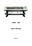
1
Operation Manual FY-8250C Thank you very much for purchasing INFINITI In order to use INFINITI correctly and safely and understand this product’s capability, please read this manual carefully. The manual includes equipment structure, description, technical parameters, operation manual, safety information, application of software, etc. This manual is subject to change without notice. Contents herein contained are believed to be correct, however, please contact us if you find any error or something not clear enough. Copyright 2004 Infiniti. All rights reserved. November 12, 2004 Version 1.0 FY -8250C Operation Manual -2- FY -8250C Operation Manual INDEX CHAPTER 1 SAFETY INFORMATION 1.1 Important Safety Information 1.2 Caution When Using Printer 1.3 Guide When Using Ink Cartridge 1.4 1.5 Choosing Printer Installation Place Warning, Caution and Attention CHAPTER 2 TECHNICAL PARAMETERS CHAPTER 3 EQUIPMENT ASSEMBLY AND ADJUSTMENT 3.1 Assemble Printer 3.2 Attention before Turning on FY-8250C 3.3 Port of printer 3.4 Usage and Maintains of printer 3.5 Connect with power CHAPTER 4 EQUIPMENT STRUCTURE AND ACCESSORIES CHAPTER 5 BASIC PANEL OPERATION 5.1 Menu Structure of Control Panel 5.2 Function Description in Details 5.3 Printing Steps CHAPTER 6 DESCRIPTION OF INK SUPPLY, CLEANING SYSTEM AND BOARD 6.1 Ink Supply and Cleaning System 6.2 Assistant Board CHAPTER 7 7.1 7.2 7.3 7.4 7.5 7.6 INK SUPPLY SYSTEM Summary System Diagram Function Description Operation Description Intelligent Detection Function Intellectualized Manual Button CHAPTER 8 CLEANING SYSTEM 8.1 Summary -3- FY -8250C Operation Manual 8.2 8.3 CHAPTER 9 9.1 9.2 9.3 9.4 System Diagram Operation Description HEATING SYSTEM Summary System Diagram Function Description Working Process and Characteristics CHAPTER 10 SOFTWARE OPERATION 10.1 Installation 10.2 Application Of Printer Driver 10.3 Equipment adjustment: 10.4 Operation of RIP -4- FY -8250C Operation Manual Chapter 1 SAFETY INFORMATION 1.1 Important Safety Information Before use your INFINITI FY-8250C InkJet Digital Printer, Please read following safety information. Pay attention to the cautions on the Printer. • • • Do not block the hole on the cover. Do not insert any object into the Printer groove. Don’t let any kind of liquid splash into Printer. Only use the power supply according to the label. You may choose either AC 110V or 220V for different countries and regions. • Connect all the equipment to a proper-grounded socket. Avoid the socket in the same circuit with copy machine or air conditioner. • • Avoid to using the socket controlled by the wall switch or by auto timer. Please keep Printer away from the latent source of electromagnetic disturbance. For example, loudspeaker or wireless phone. • If you use additional cable, please make sure that total amperage of the equipment connecting with cable shall not exceed the amperage of the power supply. Moreover, the amperage of all equipment connecting with wall socket does not exceed the amperage of the wall socket. • Do not use damaged Electrical Power wire. • Do not repair Printer by yourself. • Shut off the power and ask experienced technician for help, if the following situations occur: Power cable or plug is damaged. Liquid splashes into printer. Printer falls down or broken. Printer cannot work properly or change in property. 1.2 Caution When Using Printer • • Don’t use your hand to move print head; otherwise the printer will be damaged. Always use power switch to turn On/off the printer. Before shutting down the Printer, do not pull out Power Supply wire or Data Wire. • Before moving the printer, please make sure the print head is fixed at original position. 1.3 Guide When Using Ink Cartridge • • Keep ink away from children. Do not let the children drink or touch. If ink spills on the skin, please wash with soap and water. If ink splashes into eye, please wash with water immediately • • Do not shake the ink cartridge in case ink leak is caused. After using for a certain period (generally 3 months), you should take off the ink cartridge, clean it and dry it. • Please keep surrounding clean when you replace a new ink container. It helps you improve printing quality. -5- FY -8250C Operation Manual 1.4 Choosing Printer Installation Place • Put printer at a horizontal and stable place with enough space; otherwise, the Printer may not work properly. • Don’t leave Printer at a place where temperature and humidity change severely. Avoid direct sunlight, strong light or heat. • • • 1.5 Avoid shaking or vibrating. Keep sufficient room around printer for air circulation. Place printer nearby the wall socket, so that it is easy to connect or disconnect the power supply Warning, Caution and Attention Warning Must obey in order to ensure personal safety. Caution Must obey in order to protect the machine. Attention Contain some important and useful information about operation. -6- FY -8250C Operation Manual Chapter 2 TECHNICAL PARAMETERS Figure2-1 Printer Outlook Product Model FY-8250C, FY-8250C+ Print Technique Xaar 126 piezo head, 8 heads inside Resolution 200dpi、400dpi Max Media Width 2540mm Max Printing Width 2500mm Output (m²/h) Mode Output (m²/h) 200dpi 2pass 32.37 200dpi 3pass 22.57 200dpi 4pass 17.10 400dpi 17.10 Display LCD display with 8 key panel, self-diagnosis available Ink Type Solvent-base ink:C, M, Y, K and flush solution Ink Supply Mode 300ml/min auto ink supply by electric pump,volume of main tank 800ml/color Auto/manual ink supply, low ink detector Ink Inspection System -7- FY -8250C Operation Manual Printing Driver Support many RIP drivers and operation platforms (Window2000, XP, etc.) Flex, vinyl, window film, polyester, etc. Media Type Roll media or sheet media (bigger than A4 or 210mm) Media Processing Auto feeding and take-up system Print head Height weight less than 40kg/roll 2mm-4mm above media adjustable Pre-heater & Dry System Front-rear temperature control, two-digit LED display, temperature 30°C-60°C adjustable Manual adjustment media width Clamp Print head Cleaning System Safety System Auto negative pressure cleaning / semi-auto positive pressure cleaning / cleaning with flush solution Inside safety lock with auto shutting down function Print Interface USB2.0 interface or High speed data transmission PCI card Noise Printing status≤60dB/waiting status≤40dB (ISO7779) Printer Size (including tank) / Net Weight Package Size / Weight ink Input Voltage L 3,600mm×W 870mm×H 1,270 mm / 360kg L 3,720mm×W 925mm×H 1,090 mm / 450kg AC 100 - 240 V, 50HZ/60HZ (Heating voltage can be set to be manual setup by an engineer; Voltage for the Feeding and Cleaning System Power(AC 220V applied) Controlling voltage is auto setup.) AC 220V, 50HZ/60HZ(AC 110V optional) Control:≤ 3A Heating:≤ 5A Software Platform Feeding、cleaning:≤ 5A Window2000、XP Working Environment Temperature:20°C - 28°C The parameters above are subject to change without notice. -8- FY -8250C Operation Manual Chapter 3 EQUIPMENT ASSEMBLY AND ADJUSTMENT 3.1 Assemble Printer Remove Screw Remove Screw Figure 3-1 Packaging Screw’s Removing 1. Please assemble supporter according to the figure above. 2. Please tighten all screws on the supporter; 3. Put the printer on supporter with sufficient manpower. Make sure the printer stable enough. 4. Install auto ink supply system on right side. 5. Please connect all power cables correctly. 3.2 Attention before Turning on FY-8250C 1. In order to clean print head easily, please prepare following items: • Flush solution • Non-woven fabric. 2. In order to inspect temperature and humidity of printing environment, please prepare relative measurers. Requirement for environment: • Temperature: 20°C - 28°C • Humidity: 40% - 70% 3. Power supply • • • • • • • You may select AC 110V or 220V for different countries or regions. • It is better to use UPS stable-voltage power. Control power supply: AC 100 - 240V 50/60HZ Heating power supply: AC 100 / 240V 50/60HZ (AC 100 V optional) Feeding power supply: AC 100 / 240V 50/60HZ (AC 100 V optional) Cleaning power supply: AC 100 / 240V 50/60HZ (AC 100 V optional) Please choose the type of power shown on the printer in case of damage to the printer. Make sure the printer is well grounded. 4. Requirement for computer -9- FY -8250C Operation Manual In order to avoid problems caused by computer, please choose high quality computer or brand computer such as DELL or IBM, etc. 3.3 Print Interface The print interface has two forms: 1. Data card Put the data card into computer’s PCI slot, then connect data card with computer’s COM port by cable. Connect data card with print cable port by data cable. 2. USB2.0 Connect the printer’s USB port with computer’s USB port directly by data cable. USB driver procedure finishes automatically when Try Setup is installed. 3.4 Print head Usage and Maintenance 3.4.1 Print head installation Install the print head on the print head frame. Up skew Leftskew Right skew The way for installation: Loosen the Up skew and Left skew on the print head frame. Take out the Right skew and stick in the print head down to the frame. And then put on the Right skew and tighten all of the skews. Don’t forget to nip the plug on the ink tube with a clip, which is one of the spare parts in the spare parts box. 3.4.2 Print head Usage 1、Flush liquid out of the print head For print head protecting, lots of liquid is injected into the print head before it is used. The liquid must be flushed out for the first time using. Before fixing the print head on the print head frame, operate as follows: joint a filter on the In-tube of the print head, and then joint an injector--which fills with flush solution--on the filter. Inject 10-20 ml flush solution to the print head to eject the liquid inside. Then fill the print head with flush solution for complete dissolving within 5-10 minutes. Finally, flush the print head with about 30ml flush solution to eliminate the liquid completely. Make sure to operate on a stable and clean platform. Steps: ① Suck some 20ml cleaning solution in the injector. ② Inject cleaning solution into the inlet of the print head and let it flow out of the outlet. (some 15ml) ③ Plug up the inlet of print head and let solution flow out of the nozzles. - 10 - FY -8250C Operation Manual ④ keep the print head stillness for some 10 minutes. And repeat the action of ① to ③. Notice: 1 Operate on a clean and convenient table. 2 Never touch the surface of nozzles and socket of the print head with your fingers. 3 The injector should be filtrated with a filter. 4 Extend the outlet of the print head with an ink tube and ensure cleaning solution won’t inpour into the socket. 5 Never touch the nozzle surface with other objects. 6 Dispose the inlet and outlet carefully. 7 The force to inject cleaning solution can’t exceed 0.3kg. 2、Extrude air from the print head After fixing the print head on the print head frame (be cautious of the in tube and out tube). Remove the Cap from the Out tube; positive-pressure clean to fill the print head with ink till ink streams out from nozzles. During the process air is extruded completely from the print head. 3、Wet the print head surface After extruding air from the print head, cover the Cap on the Out tube. Positive-pressure clean again until ink streams out from the nozzles, then wipe on the print head surface with a clean stick to form a protecting coat on the print head surface. The ink on the surface will stream into the nozzles because of negative pressure. Notes: When ink on the print head surface streams into nozzles completely and the surface is dry, never wipe on the print head surface, because that will orient air into the nozzle and shape bubbles in the pipelines and affect the printing quality. - 11 - FY -8250C Operation Manual 2 4 5 3 1 1-Print head 2-Ink In Tube 3-Ink Out Tube 4-Connector Cap 5-Tube F Connector 4、Test printing Design some color blocks as 20x20cm with some image operating software, and set color luminance to 100%, 50% and 10%. Print the color blocks under test mode and check the print result. If the print result is normal which means no ink-break and no ink spots on the mediums, the printer can work normally. 3.4.3 Print head cleaning and maintenance 1. Ink replacing Flush the print head with the original ink first, and then flush it again with new flush solution, which match the new ink. 2. Print head cleaning If low quality printing takes place, a positive-pressure cleaning is proper for the print head. After positive - 12 - FY -8250C Operation Manual pressure cleaning, wipe the print head surface with a clean stick to stop the ink streaming out of the nozzles. Be sure not to use a stick with flush solution to wipe the print head surface, otherwise, the flush solution will stream into the nozzles. 3. Liquid preservation of the print head If use liquid preservation frame to preserve the print head, put a clean non-woven fabric on sponge and drop some flush solution on it; if not, adhibit a clean non-woven fabric with some flush solution on the print head and wrap the print head with a velum. 3.5 Switch on power 1. After all parts are installed, put the printer at the proper place. Removing carefully all the packaging materials like foam, adhesive tape. 2. Connect power cables and data cables. Power protective switch can only control heating power and it is at open status in normal condition (It’s in the open status when far from red point). 3. After everything is ready, switch on power. 4. Load media. 5. Test to check if print head is good to print. If the test result is unsatisfactory, you should clean print head. - 13 - FY -8250C Operation Manual Chapter 4 EQUIPMENT STRUCTURE AND ACCESSORIES 6 1 3 5 7 4 2 8 9 10 Figure 4-1 Front View - 14 - FY -8250C Operation Manual 13 11 14 12 15 Figure 4-2 Media feeding and take-up motor 1 16 17 18 Figure 4-3 Partial - 15 - FY -8250C Operation Manual 20 22 19 21 Figure 4-4 Back View 24 27 25 23 26 Figure 4-5 Partial - 16 - FY -8250C Operation Manual 29 30 28 31 Figure 4-6 Partial 1. Print head:8 piezo print heads 2. Media:A wide range of media available 3. Printing Board:Platform for printing 4. Power Switch:Turn on/off printer 5. Press Roller Control Pole:Control press roller up / down for media feeding 6. LCD Control Panel:Set up and execute function and mode 7. Heating board:Heat media to dry the ink on the media 8. Main Waste Ink Tank:Collect the waste ink during cleaning - 17 - FY -8250C Operation Manual 9. Waste Ink Groove: Collect the waste ink during cleaning 10. Media Auto-feeding sensor: Control media feeding motor running 11. Media Feeding motor: 12. Media Feeding Roller:roller driver 13. Media Feeding System Switch:to make media feeding roller turn forward or backward 14. Media Feeding Manually/Automatically Switch:manually control or automatically control or shut down media feeding motor. 15. Media peel off setting: 16. Press Roller:Press media and make media smoothly 17. Clamp:Manually adjust media width 18. Flash Protector Frame:prevent ink splash 19. Print Interface:USB2.0 interface or connect to data card in computer 20. Power Socket:Provide power for printer 21. Heating Power Socket 22. Heater Protective switch:to prevent electricity leakage of heating board 23. Assistant operation board:Control print head positive pressure cleaning and set heating temperature 24. Ink pump: provide ink to sub ink tank 25. Ink filter: Filtrate impurity in ink. 26. Valve: Automatically control the air route 27. Air pump: Compress air as positive cleaning the print head. 28. Sub ink tank: Store ink. 29. Safety tank: Store air. Prevent ink leak out while float switch inside sub ink tank is broken. 30. Valve: manually control the air route 31. Tube clamp: cut air - 18 - FY -8250C Operation Manual - 19 - FY -8250C Operation Manual Chapter 5 BASIC PANEL OPERATION 5.1 Menu Structure of Control Panel LCD Displa Direction Key Function Key Figure 5-1 Control Panel Function Keys 1. Direction (Arrow) Key 2. Function Key 1) ONLINE:Switch between online and offline mode; Press for 3-4 seconds for a pause 2) ESC:Back to the upper menu 3) ENTER:Confirm the command and execute it 4) FUNC:In self-diagnosis mode when offline; Shortcut to the cleaning position in Clean Pos mode. 3. Basic Operation After turning on printer, X move self-tests first and then Y motor. After self-test, carriage goes back to the original position. You will see the following information displayed on the LCD screen: • Mark /// INFINITI with machine model • Version • Then back to basic operation menu. The machine is in normal conditions if shown as below. FY8250C Ver 4.3E MENU - > 1.Moving System 2.Clean Tools 3.Adjustment OFFLINE 4.Options - 20 - + + + + FY -8250C Operation Manual Figure 5-2 Main Menu “+” stands for containing submenu. “– ” stands for containing no submenu. In this case, press / key to circularly display these four menus up and down. When there’s a “+” after the menu arrow (that is the first line on menu), press ENTER key, and submenu will be displayed. For example, when the arrow point to “1.Moving system”, press ENTER key, and it will display on the LCD screen as follows: MENU → M1 OFFINE 1.X-Move 2. Media Detect 3.Clean POS 4.Print POS - “M1” stands for the submenu of the first main menu. In this case, press ESC key, and it will go back to main menu. Press / key to circularly display these four menus up and down. When there’s a “–” after the menu arrow (that is the first line on menu), press ENTER key to execute operation. Press ESC key to exit. 5.2 Function Description in Details Main Menu Submenu Description - 21 - FY -8250C Operation Manual Moving XMove After pressing ENTER, “MOVE” flashes on LCD. Move the media by pressing key / . After media moves to the right position, press “ENTER”. Media Detect After pressing ENTER, print head will traverse along the Y-rail only once to detect media, and then stop in front of the beginning of media. If LCD displays “ERROR”, please check if media or sensor is not installed (Now this function is not available.) Clean POS Press ENTER. LCD displays the set value “XXXX”. Its unit is mm. Press “FUNC” to move the head quickly to the set position. If it does not reach the cleaning position exactly, adjust by pressing . Then press ENTER to save this value. System Use this function when cleaning print head. Enter this function; LCD displays number “XXXX”. Press FUNC, print head moves to the set position automatically. If press at the moment, print head will purge automatically. Clean Tools Print POS After pressing ENTER, LCD displays number “XXXX”, and then press to make the head move right or left. After moving to the desired position, press ENTER to save. Later printing or test printing will start from this position. CLEAN ALL After you press ENTER, print head moves to the cleaning area to clean with negative pressure automatically, and than back to the original position. After you press ENTER, LCD displays “JET”. Print head jets ink to prevent clogging. “JET” disappears after jetting finishes. If you want to repeat, press ENTER again. In this mode, ink amount jetted is middle. Ink amount can be changed by option “Purge Quantity” under “Option”. Purge Ⅱ Purge Ⅲ After you press ENTER, LCD displays “JET”. Print head jets ink to prevent clogging. “JET” disappears when jetting finishes. If you want to repeat, press ENTER again. In this mode, ink amount jetted is big. Ink amount can be changed by option “Purge Quantity” under “Option”. JAM TEST After pressing ENTER, start test printing. (It is same to press FUN under the OFFLINE mode.) - 22 - FY -8250C Operation Manual Adjustment Moving Test After pressing ENTER, LCD displays as below: MENU - > Moving Test M3-1 Press <FUNC> to run test and Press <ESC> OFFLINE to stop Print Speed Follow guide to operate. Printer is under simulate-printing mode, and the head does not jet ink. It is mainly for test purpose. Horizontal speed has 12 shifts ranging from 0 to 11. After you press ENTER, it displays as follow: MENU - > M3-2 Print Speed XXXX Default is 4 OFFLINE BID adjust Press to adjust the value. Printing quality under highest speed 11 is not best. It is recommended to choose speed below 10, and optimal is 8. This function isMENU used to-adjust print head, in order to prevent > BIDthe Adjust overlapping under BID printing. After pressing ENTER, LCD M3-3 XXXX displays as below: OFFLINE - 1> and Rectangle Adjust Press to add MENU or deduct press to add or deduct 20. It is , M3-4 Rectangle XXXX necessary to use the FY-8250C driver software at the same time. OFFLINE Please refer to the software instructions in the following chapter. This function is to adjust the feeding rectangle in Y direction. After you press ENTER, LCD displays as follow: Pressto add or deduct 1,and pressto add or deduct 20. To the type FY-8250C+, it’s no use. You should adjust the value in “Print setup \ Important setup \ Feed compensate”. - 23 - FY -8250C Operation Manual Options Purge Times Purge Quantity Paper Detect Fan Velocity Set it to purge automatically after printing several lines. No purge when the value is 0. Set the amount of purge after cleaning, and amount of PURGE Ⅲ in M2 when cleaning manually. Note: The value cannot be set too large. Otherwise it may affect the print quality. Check whether the paper is exhausted. 0 means not to detect ; 1 means to detect automatically. The function is not available so far, so you must set 0. Used to set suction value to media. Set the velocity between 0 and 255, and the normal value around 128. 5.3 Printing Steps On normal condition, the steps are as follows: 1. Power on printer 2. Turn on computer Note : It is recommended to turn on the printer before computer. Otherwise the connection may fail. 3. Install media, put down the press bar to press on media. 4. Clean the head and start the self-diagnosis till no nozzle clogging. 5. Press ONLINE. MENU - > 1.Moving System 2.Clean Tools 3.Adjustment OFFLINE 4.Options + + + + ONLINE MODE Offline mode Online mode 6. Trim the pattern for printing, and save it in computer. 7. Open INFINITI RIP. 8. Create new file. 9. Read the pattern for printing. 10. Adjust the position, size, property, and resolution of the pattern. 11. Printer setting 1) Select File/Printer setting. Below dialogue box shows: 2) Select the type of printer “FeiYeung Printer” and the model “FY-8250C”. - 24 - FY -8250C Operation Manual 3) Click the “Printer setting”. Set the relevant value in the following dialogue box. a. Select the printing resolution. b. Select BID or single direction printing. BID has higher efficiency than single direction. 4) Click“color tune”to activate following dialogue box. Note: Details of the functions above and others referred to the INFINITI RIP Manual 12. Click “Printing Project” to print. 13. LCD displays as below when printing: PRINT PROJECT LINE : TOTAL : XXXX FINSH : XXXX RIP READY : XXXX 14. If clog while printing , Total lines Finished lines RIP ready lines pause printing by pressing ONLINE for a longer time. After cleaning, press ONLINE to go on. (Cleaning procedure: To avoid the nozzle clogging while printing, you can press ONLINE key for a pause. Press key to make the print head move to leftmost cleaning position and do the cleaning operation by selecting F2 on assistant board. Press key to make the print head jet ink automatically; Press key to let the print head execute automatically F2 task and negative pressure cleaning. When finishing, press ENTER key to continue printing. Press key to let the print head move to original position. Press ESC key to cancel the printing operation. Do not switch mode from ONLINE to OFFLINE until “printing cancel” shows up on computer. ) 15. Press ONLINE when the printing is all finished. Then the printer is under the Offline mode. Note: If want to stop during printing, usually stop it in RIP. If stop it directly on the printer and cancel this printing, printer is OFFLINE until menu “printing cancel” appears in software. - 25 - FY -8250C Operation Manual Chapter 6 DESCRIPTION OF INK SUPPLY, CLEANING SYSTEM AND BOARD 6.1 Ink Supply and Cleaning System 1 2 3 4 5 Figure 6-1 Ink Supply and Cleaning System ( Right Side) 1. Main Tank C 2. Main Tank M 3. Main Tank Y 4. Main Tank K 5. Main Tank F Figure 6-2 Ink Supply and Cleaning System(Seen from Back) - 26 - FY -8250C Operation Manual 7 12 11 9 10 13 6 8 1 2 3 4 5 Figure 6-3 Ink Supply and Cleaning System(Seen from Back) 1. Sub Tank C 2. Sub Tank M 6. Floating Switch (in sub-tank) 11. Tube connector F 3. Safety Tank 7. Ink in Tube 12. Air valve 4. Sub Tank Y 5. Sub Tank K 8. Ink out Tube 9.Air Tube 10.Tube connector M 13.clamp Ink in tube Tube connector cap Printhead Figure 6-4 Ink Supply and Cleaning System(Seen from Front) - 27 - 3 FY -8250C Operation Manual Figure 6-5 Flushing Valve 4 、Handle 1 、M Port 2 、F Port 3 、F Port Figure 6-6 Valve Handle:Handle’s arrow direction means the line is closed Tube Connector: Channel connected by M tube connector and F tube connector. Tube Cap:To seal ink line. 6.2 Assistant Board Assistant Board has many functions. It can control ink supply, cleaning and heating. 7 8 9 10 - 28 - FY -8250C Operation Manual 6 5 1 2 3 4 Figure 6-6 Assistant Board 1、K1 Function Key,used to select any function, including: F1 --:Exit,back to temperature display F2 AP: Start air pump(Low Ink) F3 AP: Start air pimp(Medium Ink) F4 AP: Start air pump(High Ink) F5 TF: Set up temperature of front heater,adjustable between 30℃~60℃ F6 TR: Set up temperature difference between rear heater and front heater, 0℃~8℃ adjustable (temperature in the rear is lower than the front). 2、K2 To adjust temperature( 0℃~9℃ adjustable), when F5 and F6 are applied. 3、K3 To display the two temperatures alternatively and adjust the values. You can increase or deduct by 10℃ when pressing this key once. 4、K4 Confirmation Key Attention : Press both K2 and K3, and then FC FP will display. Press K4 to confirm, so cleaning pump starts. 5、Digital Display Normally used to display set temperature; Display code of function if F1 is applied; Display Er when error occurs. 6、Digital Display Normally used to display actual temperature; Display code of function if F1 is applied; Display error code when error occurs. Er01, Er02, Er03, Er04 indicates lacking of ink for sub-tank of C, M, Y, K respectively; - 29 - FY -8250C Operation Manual Er05, Er06 indicates that one of the two wasted bottles is full; Er07 indicates that the safety bottle is full. 7、Socket Connect to ink pump for Cyan, marked as blue. 8、Socket Connect to ink pump for Magenta, marked as red. 9、Socket Connect to ink pump for Yellow, marked as yellow. 10、Socket Connect to ink pump for Black, marked as black. - 30 - FY -8250C Operation Manual Chapter 7 INK SUPPLY SYSTEM 7.1 Summary This ink supply system can control automatically several pumps at the same time. With perfect interface. It can adjust ink supply pressure and provides protect function. 7.2 System Diagram Ink Control Device Sub-tank Filter Floating Switch Output : Speaker Pump light Pump Print head Input : Ink Control Board Signal for floating switch Interface signal Manual ink supply button Main Tank Power Supply Figure7-1 Ink Supply System Diagram 7.3 Function Description - 31 - FY -8250C Operation Manual 1. This system can automatically control several pumps to supply ink simultaneously. 2. With perfect alarm and protection function. If any problem occurred in any pump, it will alarm and indicate which one is in trouble and the troubled one will not affect others. 3. It is easy to connect it to other systems. All floating switches signals can be input by serial port or parallel port. 4. Main controller consists of micro CPU, which can check signals using software to filter out those false ones, which is helpful to make system work more reliably. 5. The maximum ink limit is controlled by intelligent control system of main control board, in case that the electric circuit causes ink supply shortage. 7.4 Operation Description Note: please read descriptions carefully for ink supply system, cleaning system and Ink Control system before starting the following operations. 1. Preset ink supply interface and ink supply pressure. 2. As soon as the printer’s connected with power, system detects floating switch signal automatically, and then ink will be filled into sub-tank. 3. When ink channel lacks of ink, system will start the pump automatically. After the floating switch sensed the ink, the pump will work for on for a little time and then stop. 4. When ink in main tank is used out, or the ink pump has been running for too long time, the system will alarm and display error code. Press K4 on assistant board to reset, and system goes back to normal process. K4 Figure 7-2 Assistant board 7.5 Intelligent Detection Function - 32 - FY -8250C Operation Manual Intelligent detection function for ink supply system is implemented by collecting floating switch signal with high frequency. By using concept of probability, the signal is regarded as effective if probability of floating switch signals is higher than a set value (for example, 80%). Therefore, wrong act of floating switch can affect the system’s stability much less and accordingly system’s anti-disturbance improves. 7.6 Intellectualized Manual Button Press manual ink supply button, and ink fills automatically in sub-tank up to ink level limit. - 33 - FY -8250C Operation Manual Chapter 8 CLEANING SYSTEM 8.1 Summary There are three cleaning methods: positive pressure cleaning, cleaning with flush solution and negative pressure cleaning. You choose auto cleaning or semi-auto cleaning, according to actual circumstances: before printing, during printing or idle for a long time. 8.2 System Diagram Air Filter Safety Ink Tank Valve Ink Filter Output : Pump light Cleaning Solution Light Liquid Valve Print head Floating Switch Assistant Board Air Filter Ink Control Board Air Pump Main Tank Power Supply Figure 8-1 Cleaning System Diagram 8.3 Operation Description Positive Pressure Cleaning - 34 - Input : Data Signal Pressure Signal Clean Valve Signal FY -8250C Operation Manual K1 Figure 8-2 Operation Panel Key Move print head to cleaning position, press K1 on assistant board, select F2: 1 With pressure got from the air pump, ink will be purged through the head and ink channel, so as to clean them. 2 Three options for air pressure level: F2—Low;F3—Medium; F4—High. Note: normally, do not use F4, since it’s ink consuming. Chapter 9 HEATING SYSTEM 9.1 Summary This heating system can adjust temperature based on different PVC material and surrounding. It can adjust the temperature automatically to keep temperature constant. Customer can have satisfactory printing effect. 9.2 System Diagram Temperature adjust switch Temperature feedback signal Heating Driver Heating signal 1 Heating Driver Back heater DIP1: Temperature setting Light 1 SCM Front heater Light 2 Heating signal 2 Heating control board 110V or 220V Temperature adjust switch - 35 - Comprehensive Assistant Board Operation Board FY -8250C Operation Manual Figure 9-1 System Diagram 9.3 Function Description 1、To keep the front and rear heating boards in auto constant temperature. 2、 With advanced protective functions to avoid over-heating, leakage, etc. The line will be cut off automatically if a certain line’s temperature is over 75° C. As soon as the temperature lowers, it will resume heating. Over heating will not occur when the entire input signal is cut off. 3、 The system can work independently and can be easily transplanted. It is easy to convert input voltage from AC110V to 220V. 4、 Based on different media and surrounding, customers can easily adjust temperature with the function F5 by pressing K1 on the operation board. 5、 The heating system is controlled by advanced intelligent microprocessor; it has features of heating up quickly, controlling temperature accurately and saving energy. 6、Two heaters are used. It is easy to install, with no extra space needed and longer lifetime. 9.4 Working Process and Characteristics 1. To set up basic temperature (30℃ ~ 60℃) by function key F5 under K1 on operation board. Temperature difference (0℃~8℃) between the front and the rear can be set up by function key F6. 2. Heating power supply is independent from control power supply. Please turn on the heating power before turning on the power for the printer. Once the power is on, the system heats up automatically to set temperature and keeps the temperature at the set value. Without turning on power for printer, the heating system will not work. However, there is still AC 220V inside machine. 3. Temperature detector lies about 50cm to the right physical printing original position. Print media should cover this region when printing. 4. After printing, make sure to turn off the two powers. - 36 - FY -8250C Operation Manual Chapter 10 SOFTWARE OPERATION 10.1 Installation 1. Installation of Infiniti RIP Software: see the RIP User’s Manual for details. a) Insert RIP CD into computer’s CD-ROM b) Run setup.exe c) Follow the instruction to finish the installation 2. Installation of printer driver )a Insert installation CD of FY series printer into CD-ROM )b Run setup.exe under directory of Try Setup.CHL V5.0T )c Follow the instruction to finish the installation Note:Please use the default directory for the installation. 10.2 Application Of Printer Driver Note:The FY series printer driver program is only for engineer to adjust the print head ,and not necessary for normal operation. 10.2.1 Enter TRY 1. Click start\Program\Try, enter Try system. - 37 - FY -8250C Operation Manual 2. Open TRY 3. First, choose the type of printer. Click “Printer” menu,choose “FY-8250C/FY-8320C/FY-8320C+”. 4. Then open “File” to adjust some settings. - 38 - FY -8250C Operation Manual In these menus, most important is print setting. 10.2.2 Print Setting This function is to set the printing parameter, print mode, uni-direction, BID and the color of ink. Note: Usually the four colors should all be selected. Only when the engineer adjusts the position of head, one certain color is chosen to modify the printing parameter. Print Mode: There are 7 modes for choosing: Test mode, 200 2Pass, 200 4-2Pass, 200 3Pass, 200 6-3Pass, 200 4Pass, 400 DPI Explanation: Test mode: Just 200 1Pass. 200dpi of horizontal resolution and print once at feeding direction 200 2Pass: 200dpi of horizontal resolution and print twice at feeding direction. Ink volume is twice of 200 1Pass, but printing speed is just 1/2. 200 4-2Pass: print quarter under half of 200dpi for horizontal resolution and involving twice at feeding direction. Ink volume is twice of 200 1Pass, but printing speed is just 1/2. 200 3Pass: 200dpi of horizontal resolution and price thrice at feeding direction. Ink volume is 3 times of 200 1Pass but printing speed is 1/3 of 200 1Pass. 200 6-3Pass: print six times under half of 200dpi for horizontal resolution and involving twice at feeding direction. Ink volume is twice of 200 1Pass, but printing speed is just 1/2 of 200 3Pass. 200 4Pass: 200dpi of horizontal resolution and print 4 times at feeding direction. Ink volume is 4 times of 200 1Pass and printing speed is 1/4 of 200 1Pass. 400 DPI: Just 400 4-2Pass. 200dpi of horizontal resolution and print 4 times, so horizontal printing resolution is 400dpi. Printing twice at feeding direction. Ink volume is 4 times of 200 1Pass and printing speed is 1/2 of 400 2Pass. 10.2.3 Printer Parameter Setting Pressing “Printing parameter setting”, it shows warning as below: - 39 - FY -8250C Operation Manual After pressing “Yes”, you can see the dialogue box: Note: Press “load parameter” first to read the original data before adjusting. Meaning of this dialogue box: 1. Parameter of nozzle installation: Adjust the head position and overlapping of four colors. Vertical gap K2 Y2 M2 K1 C2 Y1 M1 C1 Horizontal gap H G F E D C B A(0,0) - 40 - FY -8250C Operation Manual A. Look head C1 as datum mark, its horizontal and vertical value is 0. The value is A (0, 0). B. The vertical gap between head C2 and head C1 is ensured by mechanical precision. The value of horizontal gap is B. (In above figure is 255) C. The vertical gap between head M1 and head C1 is 5 in above figure. The value of horizontal gap is C. (In above figure is 510) D. The vertical gap between head M2 and head C1 is ensured by mechanical precision. The value of horizontal gap is D. (In above figure is 765) E. The vertical gap between head Y1 and head C1 is 0 in above figure. The value of horizontal gap is E. (In above figure is 1020) F. The vertical gap between head Y2 and head C1 is ensured by mechanical precision. The value of horizontal gap is F. (In above figure is 1273) G. The vertical gap between head K1 and head C1 is 5 in above figure. The value of horizontal gap is G. (In above figure is 1531) H. The vertical gap between head K2 and head C1 is ensured by mechanical precision. The value of horizontal gap is H. (In above figure is 1786) 2. Ignore horizontal and vertical deviation: No adjustment. Only for inspect printer status. 3. BID Adjust: Adjust the print head, in order to prevent overlapping when bi-direction printing. The value is different with different speed. The value input here is the value difference between current speed and speed 4. 4. Feed Compensate:Used to adjust the feeding on the Y direction. The amount of feeding is different with different Pass. 5. COM port:Set the port for use. 6. Load parameter:Read the parameter saved in printer. 7. Input parameter: Save the parameter after modifying. 8. Curve of head voltage: (1)Press “Curve of head voltage”. The dialogue box appears. - 41 - FY -8250C Operation Manual 1) Viscosity file:Open viscosity file of ink. This curve shows the relationship between viscosity and temperature. For FY-8250C, open the file Xaar126.Ink. 2) Read Curve : Open the voltage control file. The curve shows the relationship between voltage and temperature. For FY-8250C, open the file Xaar126.Crv. 3) Save Curve:Save the voltage control file. 4) Control Curve:Control and adjust the EF value of head voltage for each color. 5) Upload:Save data to printer. 6) Download:Read relevant data from printer. Users can also select “All”, and then press “Download”. All the relevant data of four colors will be loaded. Based on the different properties and status of ink, users can select different viscosity file and voltage control file. EF value setting: Each Xaar126 head has its own EF value. Manufacture always provides a standard EF value, which is captured under standard condition. Users input this value at column Voltage. Usually, the printing effect is good. The value is marked on the head. It is also saved in the chip of print head driver. User can download it directly. If the voltage is too high, it produces the satellites and ink supply is easy to break;If the voltage is too low, the printing line is not straight and easy to have an angle. Besides, ink volume is small and output color is light. Therefore, every head has its optimal EF value. When adjusting, you can adjust the EF value one by one. Usually user needn’t to adjust EF value. Warning:Do not change these values at will. It may cause printout overlapping or dimness. 10.3 Equipment adjustment: - 42 - FY -8250C Operation Manual Steps: 10.3.1 Enter TRY 10.3.2 Print head adjustment Select Open/File, load the file C:\try\SmallGrid126.group SmallGrid126.group In “Print setting”, select test mode,single direction, color “C”. Press printing , and print color “C”. The line should be vertical on the vertical direction. If not, adjust the angle of head. Feeding direction Head moving Start position Effect of vertical line Adjusting the head Adjust head installation angle After adjusting the head of color “C”, do the same adjustment to the other heads. During adjustment, do not change “Printer parameter setting”. 10.3.3 Feed Compensate adjustment Select Open/File, load the file C:\try\SmallGrid126.gro. In “Print setup”, select test mode , single direction , color “C”. Press printing key , and print with color “C”. Adjust the value in Print setup \ Important setup \ Feed Compensate” until the grid becomes perfect, and then save the value. If there is space in printout, reduce the value; if overlap, add. The rest passes can be adjusted in the same way. 10.3.4 Four colors overlapping adjustment Take “C” for datum line and adjust another color together with “C”. Adjust M, Y, K one by one and print at test mode, single direction. See below: Reduce value X M 、Y 、K Add value Y - 43 C ( datum line ) C 、M 、Y 、K overlap adjustment no FY -8250C Operation Manual Following above guide to adjust “Head nozzle installation parameter” in “Printer parameter setting”, and input values in the blank behind the distance coefficient. The prior is X, and the latter is Y. Note: usually printer’s horizontal and vertical distance are finished adjusting when deliver. User needn’t adjust. Only after long transportation and CMYK cannot overlap, user can go to this function to adjust. 10.3.5 BID adjustment: Follow below steps: In the control panel, Adjustment\Speed setting is 4. 1. 2. 3. Press ONLINE. Use Fy8250C software to open the adjustment file BID_test.group. BID_test.group 4. Press printing key to print. 5. Check the printout whether every line is straight. Then input the value in Adjustment \ BID adjust. If some of them are straight while others not, you can input the value in dialog “Important 6. Setup\BiComp” for each print head. Note: Different speed has its own BID rectangle value. 10.4 Basic operation of RIP Refer to INFINITI RIP Manual. Please close the printer driver software before opening RIP. - 44 -