1
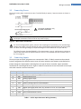
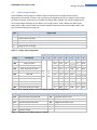
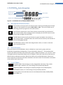
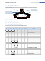
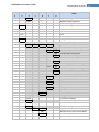
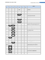
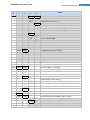
PLATINUMTM Series User’s Guide
Introduction
1
For complete product manual:
www.omega.com/manuals/manualpdf/M5451.pdf
CN32Pt, CN16Pt, CN16DPt, CN8Pt, CN8DPt
Temperature & Process Controllers
The information contained in this document is believed to
be correct, but OMEGA accepts no liability for any errors it
contains, and reserves the right to alter specifications
without notice.
OMEGA’s policy is to make running changes, not model
changes, whenever an improvement is possible. This
affords our customers the latest in technology and
engineering. OMEGA is a registered trademark of OMEGA
ENGINEERING, INC. © Copyright 2015 OMEGA
ENGINEERING, INC. All rights reserved. This document
may not be copied, photocopied, reproduced, translated, or
reduced to any electronic medium or machine-readable
form, in whole or in part, without the prior written consent of
OMEGA ENGINEERING, INC.
MQS5451/0315
PLATINUMTM Series User’s Guide
Introduction
1. Introduction
The PLATINUMTM Series controller offers unparalleled flexibility in process measurement. While the
controller is extremely powerful and versatile, great care has gone into designing a product that is easy
to set up and use. Automatic hardware configuration recognition eliminates the need for jumpers and
allows the unit’s firmware to automatically simplify itself, eliminating all menu options that do not apply
to your configuration.
Each unit allows the user to select the input type from 9 thermocouple types (J, K, T, E, R, S, B, C, and N),
Pt RTDs (100, 500, or 1000 Ω, with a 385, 392, or 3916 curve), thermistors (2250 Ω, 5K Ω, and 10K Ω), DC
voltage, or DC current. The analog voltage inputs are bidirectional and both voltage and current are fully
scalable to virtually all engineering units with a selectable decimal point that is perfect for use with
pressure, flow, or other process inputs.
Control is achieved using the PID, on/off, or heat/cool control strategy. PID control can be optimized
with an autotune feature; and in addition, a fuzzy logic Adaptive Tuning Mode allows the PID algorithm
to be continuously optimized. The instrument offers up to 16 Ramp and Soak segments per Ramp and
Soak program (eight each), with auxiliary event actions available with each segment. Up to 99 Ramp and
Soak programs can be stored, and multiple Ramp and Soak programs can be chained, creating
unmatched ramp and soak programming capability. Multiple Alarms can be configured for above,
below, hi/lo, and band triggering using either absolute or deviation Alarm trigger points.
The PLATINUMTM Series controller features a large, three-color, programmable display with the
capability to change color every time the Alarm is triggered. Various configurations of mechanical relay,
SSR, DC pulse, and analog voltage or current outputs are available. Every unit comes standard with USB
communications for firmware updates, configuration management, and data transfer. Optional Ethernet
and RS-232 / RS-485 Serial communications are also available. The Analog Output is fully scalable and
may be configured as a proportional controller or retransmission to follow your display. The universal
power supply accepts 90–240 Vac. The low-voltage power option accepts 24 Vac or 12–36 Vdc.
Additional features usually found only on more expensive controllers make these the most powerful
products in their class. Some additional standard features are remote Setpoint for cascaded control
setups, High-high/Low-low Alarm functionality, external latch reset, external Ramp and Soak program
initiation, combination Heat/Cool Control Mode, configuration save and transfer, and configuration
password protection.
2
PLATINUMTM Series User’s Guide
Safety Considerations
2. Safety Considerations
This device is marked with the international caution symbol. It is important to read this manual before
installing or commissioning this device as it contains important information relating to Safety and EMC
(Electromagnetic Compatibility).
This instrument is a panel mount device protected in accordance with EN 61010-1:2010, electrical safety
requirements for electrical equipment for measurement, control, and laboratory use. Installation of this
instrument should be done by qualified personnel.
In order to ensure safe operation, the following instructions must be followed and warnings
observed:
This instrument has no power-on switch. An external switch or circuit-breaker must be included in the
building installation as a disconnecting device. It must be marked to indicate this function, and it must
be in close proximity to the equipment within easy reach of the operator. The switch or circuit-breaker
must comply with the relevant requirements of IEC 947–1 and IEC 947-3 (International Electrotechnical
Commission). The switch must not be incorporated in the main supply cord.
Furthermore, to provide protection against excessive energy being drawn from the main supply in case
of a fault in the equipment, an overcurrent protection device must be installed.
•
•
•
•
•
•
•
Do not exceed the voltage rating on the label located on the top of the instrument housing.
Always disconnect the power before changing the signal and power connections.
Do not use this instrument on a work bench without its case for safety reasons.
Do not operate this instrument in flammable or explosive atmospheres.
Do not expose this instrument to rain or moisture.
Unit mounting should allow for adequate ventilation to ensure that the instrument does not
exceed the operating temperature rating.
Use electrical wires with adequate size to handle mechanical strain and power requirements.
Install this instrument without exposing the bare wire outside the connector to minimize
electrical shock hazards.
EMC Considerations
•
•
•
•
Whenever EMC is an issue, always use shielded cables.
Never run signal and power wires in the same conduit.
Use signal wire connections with twisted-pair cables.
Install Ferrite Beads on signal wires close to the instrument if EMC problems persist.
Failure to follow all instructions and warnings is at your own risk and may result in property
damage, bodily injury and/or death. Omega Engineering is not responsible for any damages or
loss arising or resulting from any failure to follow any and all instructions or observe any and all
warnings.
3
PLATINUMTM Series User’s Guide
Wiring Instructions
3. Wiring Instructions
3.1
Back Panel Connections
Ethernet Connector if EIP Option Installed
Ethernet Communications Status
LEDs if EIP Option Installed
USB Connector
8-Pin Power / Outputs Connector
10-Pin Input Connector
Figure 1 – CN8Pt Models: Back Panel Connections
8-Pin Power / Outputs Connector
Ethernet Connector if EIP
Option Installed
Ethernet Communications Status
LEDs if EIP Option Installed
Figure 2 – CN16Pt and CN32Pt Models: Back Panel Connections
10-Pin Input Connector
USB Connector
4
PLATINUMTM Series User’s Guide
3.2
Wiring Instructions
Connecting Power
Connect the main power connections to pins 7 and 8 of the 8-pin power / output connector as shown in
Figure 3.
Use copper conductors only
for power connections
Caution: Do not connect power to your device until you have completed all input
and output connections. Failure to do so may result in injury!
Figure 3 – Main Power Connections
For the low-voltage power option, maintain the same degree of protection as the standard highvoltage input power units (90–240 Vac) by using a Safety Agency Approved DC or AC source with
the same Overvoltage Category and pollution degree as the standard AC unit (90–240 Vac).
The Safety European Standard EN61010-1 for measurement, control, and laboratory equipment
requires that fuses must be specified based on IEC127. This standard specifies the letter code “T”
for a Time-lag fuse.
3.3
Connecting Inputs
The 10-pin input connector assignments are summarized in Table 1. Table 2 summarizes the universal
input pin assignments for different sensor inputs. All sensor selections are firmware-controlled and no
jumper settings are required when switching from one type of sensor to another. Figure 4 provides
more detail for connecting RTD sensors. Figure 5 shows the connection scheme for process current input
with either internal or external excitation.
Pin No.
Code
Description
1
2
3
ARTN
AIN+
AIN-
Analog return signal (analog ground) for sensors and remote Setpoint
Analog positive input
Analog negative input
4
5
6
7
8
9
APWR
AUX
EXCT
DIN
ISO GND
RX/A
Analog power currently only used for 4-wire RTDs
Auxiliary analog input for remote Setpoint
Excitation voltage output referenced to ISO GND
Digital input signal (latch reset, etc), Positive at > 2.5V, ref. to ISO GND
Isolated ground for serial communications, excitation, and digital input
Serial communications receive
10
TX/B
Serial communications transmit
Table 1 – 10-Pin Input Connector Wiring Summary
5
PLATINUMTM Series User’s Guide
Pin
Number
Process
Voltage
1
2
3
4
Rtn
Vin +/-
Process
Current
Wiring Instructions
Thermocouple
I+
I-
T/C+
T/C-
2-Wire
RTD
3-Wire
RTD
4-Wire
RTD
**
RTD1+
RTD2RTD1+
RTD1-
RTD1-
RTD2+
RTD1+
RTD2RTD1-
Thermistor
Remote
Setpoint
Rtn(*)
TH+
TH-
5
V/I In
*For Remote Setpoint with an RTD, Pin 1 on the Output Connector must be used for the RtN instead of Pin 1 on the
Input Connector. Remote Setpoint is not available if you are using an RTD sensor and you have an SPDT (Type 3)
Output installed.
** Requires external connection to pin 4
Table 2 – Interfacing Sensors to the Input Connector
1
2
3
4
5
6
7
8
9
10
RTD (100 Ω) 4-WIRE
RTD (100 Ω) 3-WIRE
RTD (100 Ω) 2-WIRE (requires pin 1
to be jumpered to pin 4)
Figure 4 – RTD Wiring Diagram
0–24 mA
Internal
Excitation
1
2
3
4
5
6
Jumper
7
8
9
10
1
2
3
4
5
6
External
Excitation
Figure 5 – Process Current Wiring Hookup with Internal and External Excitation
7
8
9
10
6
PLATINUMTM Series User’s Guide
3.4
Wiring Instructions
Connecting Outputs
The PLATINUMTM Series supports 5 different types of outputs with the model number numeric
designations summarized in Table 3. Your unit comes preconfigured with up to 3 outputs. Table 4 shows
the output connector connections for the different configurations offered. Your output configuration is
the 3 numeric digits following the first dash in your model number. Table 5 defines the abbreviated
codes used in Table 4. Please note that the SPST and SPDT mechanical relays have snubbers built in but
only on the normally open contact side.
Code
1
2
3
4
5
Output Type
3A Mechanical single pole, single throw (SPST) mechanical relay
1A Solid state relay (SSR)
3A Mechanical single pole, double throw (SPDT) mechanical relay
DC pulse for connecting to an external SSR
Analog current or voltage
Table 3 – Output Type Designations
Power
Config.
330
304
305
144
145
Description
SPDT, SPDT
SPDT, DC pulse
SPDT, analog
SPST, DC pulse, DC pulse
SPST, DC pulse, analog
8
Output Pin Number
7
6
N.O
N.O
N.O
N.O
N.O
5
Com
Com
Com
Com
Com
4
N.C
N.C
N.C
V+
V+
AC+
ACor
or
220
SSR, SSR
N.O
Com
N.O
DC+
DC224
SSR, SSR, DC pulse
N.O
Com
N.O
225
SSR, SSR, analog
N.O
Com
N.O
440
DC pulse, DC pulse
V+
Gnd
V+
444
DC pulse, DC pulse, DC pulse
V+
Gnd
V+
445
DC pulse, DC pulse, analog
V+
Gnd
V+
Table 4 – 8 Pin Output/Power Connector Wiring Summary by Configuration
Code Definition
N.O.
Normally open relay/SSR load
Com
Relay Common/SSR AC power
N.C.
Normally closed relay load
Gnd
DC Ground
V+
Load for DC pulse
V/C+ Load for analog
Table 5 – Definitions for Abbreviations in Table 4
3
N.O
Gnd
Gnd
Com
Com
Com
Gnd
Gnd
Gnd
Code
Definition
ACAC+
DCDC+
AC power neutral in pin
AC power hot in pin
Negative DC power in pin
Positive DC power in pin
2
Com
V+
V/C+
V+
V/C+
1
N.C
Gnd
Gnd
Gnd
Gnd
V+
V/C+
Gnd
Gnd
V+
V/C+
Gnd
Gnd
7
PLATINUMTM Series User’s Guide
PLATINUMTM Series Navigation
4. PLATINUMTM Series Navigation
Alarm Annunciators
Negative Sign
Process Value
Temperature Units
Setpoint Value
Program Buttons
Figure 6 – PLATINUMTM Series Display (CN8DPt Shown)
4.1
Description of Button Actions
The UP button moves up a level in the menu structure. Pressing and holding the UP button
navigates to the top level of any menu (oPER, PRoG, or INIt). This can be a useful way of
reorienting yourself if you get lost in the menu structure.
The LEFT button moves across a set of menu choices at a given level (up in the Section 5
menu structure tables). When changing numerical settings, press the LEFT button to make
the next digit (one digit to the left) active.
The RIGHT button across a set of menu choices at a given level (down in the Section 5
menu structure tables. The RIGHT button also scrolls numerical values up with overflow to
0 for the flashing digit selected.
The ENTER button selects a menu item and goes down a level, or it enters a numerical
value or parameter choice.
4.2
Menu Structure
The menu structure of the PLATINUMTM Series is divided into 3 main Level 1 groups, which are
Initialization, Programming, and Operating. They are described in Section 4.3. The complete menu
structure for levels 2-8 for each of the three Level 1 groups is detailed in Section 5.1, 5.2, and 5.3. Levels
2 through 8 represent sequentially deeper levels of navigation. Values with a dark box around them are
default values or submenu entry points. Blank lines indicate user-provided information. Some menu
items include links to reference information elsewhere in this user manual. The information in the Notes
column defines each menu choice.
4.3
Level 1 Menu
INIt
Initialization Mode: These settings are rarely changed after initial setup. They include
transducer types, calibration, etc. These settings can be password-protected.
PRoG
Programming Mode: These settings are frequently changed. They include Setpoints,
Control Modes, Alarms, etc. These settings can be password-protected.
oPER
Operating Mode: This mode allows users to switch between Run Mode, Standby Mode,
Manual Mode, etc.
8
PLATINUMTM Series User’s Guide
4.4
Complete Menu Structure
Circular Flow of Menus
The following diagram shows how to use the LEFT and RIGHT buttons to navigate around a menu.
Press the ENTER button on
oPER to select and enter RUN
Mode.
oPER
Press the LEFT and RIGHT
buttons to navigate around
the Operating Mode options.
Press the UP button to
navigate back up a level.
RUN
Stby
SP1
SP2
PEAk
VALy
It is possible to cycle through
any menu in both directions.
L.RST
SToP
PAUS
MANL
Figure 7 – Circular Flow of Menus
5. Complete Menu Structure
5.1
Initialization Mode Menu (INIt)
The following table maps the Initialization Mode (INIt) navigation:
Level
2
Level
3
Level
4
INPt
t.C.
k
J
t
E
N
R
S
b
C
N.wIR
Rtd
A.CRV
tHRM
2.25k
5k
10k
Level
5
3 wI
4 wI
2 wI
385.1
385.5
385.t
392
3916
Level
6
Level
7
Level
8
Notes
Type K thermocouple
Type J thermocouple
Type T thermocouple
Type E thermocouple
Type N thermocouple
Type R thermocouple
Type S thermocouple
Type B thermocouple
Type C thermocouple
3-wire RTD
4-wire RTD
2-wire RTD
385 calibration curve, 100 Ω
385 calibration curve, 500 Ω
385 calibration curve, 1000 Ω
392 calibration curve, 100 Ω
391.6 calibration curve, 100 Ω
2250 Ω thermistor
5000 Ω thermistor
10,000 Ω thermistor
9
PLATINUMTM Series User’s Guide
Level
2
RdG
Level
3
Level
4
PRoC
4–20
dEC.P
°F°C
FLtR
ANN.1
ANN.2
NCLR
0–24
+-10
+-1
+-0.1
FFF.F
FFFF
FF.FF
F.FFF
°F
°C
NoNE
8
16
32
64
128
1
2
4
ALM.1
ALM.2
oUt#
ALM.2
ALM.1
oUt#
GRN
REd
AMbR
Level
5
Complete Menu Structure
Level
6
Level
7
Level
8
Notes
Process input range: 4 to 20 mA
Note: This Manual and Live Scaling submenu is the same for all PRoC ranges.
MANL
Rd.1
____
Low display reading
IN.1
____
Manual input for Rd.1
Rd.2
____
High display reading
IN.2
____
Manual input for Rd.2
LIVE
Rd.1
____
Low display reading
IN.1
____
Live Rd.1 input, ENTER for current
Rd.2
____
High display reading
IN.2
____
Live Rd.2 input, ENTER for current
Process input range: 0 to 24 mA
Process input range: -10 to +10 mA
Process input range: -1 to +1 mA
Process input range: -0.1 to +0.1 mA
Reading format -999.9 to +999.9
Reading format -9999 to +9999
Reading format -99.99 to +99.99
Reading format -9.999 to +9.999
Activates degrees Fahrenheit
Degrees Celsius annunciator
Default for INPt = PRoC
Readings per displayed value: 8
16
32
64
128
2
3
4
Alarm 1 status mapped to “1”
Alarm 2 status mapped to “1”
Output state selections by name
Alarm 2 status mapped to “2”
Alarm 1 status mapped to “2”
Output state selections by name
Default display color: Green
Red
Amber
10
PLATINUMTM Series User’s Guide
Level
2
ECtN
CoMM
Level
3
Level
4
bRGt
HIGH
MEd
Low
5V
10 V
12 V
24 V
0V
USb
EtHN
SER
Level
5
Complete Menu Structure
Level
6
Level
7
Level
8
Notes
High display brightness
Medium display brightness
Low display brightness
Excitation voltage: 5 V
10 V
12 V
24 V
Excitation off
Configure the USB port
Note: This PRot submenu is the same for USB, Ethernet, and Serial ports.
PRot
oMEG ModE
CMd
Waits for commands from other end
CoNt
____ Transmit continuously every ###.# sec
dAt.F
StAt
No
yES
Includes Alarm status bytes
RdNG
yES
Includes process reading
No
PEAk
No
yES
Includes highest process reading
VALy
No
yES
Includes lowest process reading
UNIt
No
yES
Send unit with value (F, C, V, mV, mA)
_LF_
No
yES
Appends line feed after each send
ECHo
yES
Retransmits received commands
No
SEPR
_CR_
Carriage Return separator in CoNt
SPCE
Space separator in CoNt Mode
M.bUS
RtU
Standard Modbus protocol
ASCI
Omega ASCII protocol
AddR
____
USB requires Address
PRot
Ethernet port configuration
AddR
____
Ethernet “Telnet” requires Address
PRot
Serial port configuration
C.PAR bUS.F
232C
Single device Serial Comm Mode
485
Multiple devices Serial Comm Mode
bAUd
19.2
Baud rate: 19,200 Bd
9600
9,600 Bd
11
PLATINUMTM Series User’s Guide
Level
2
Level
3
Level
4
Level
5
PRty
dAtA
StoP
SFty
PwoN
RUN.M
SP.LM
LPbk
o.CRk
t.CAL
SAVE
LoAd
VER.N
VER.U
F.dFt
I.Pwd
P.Pwd
NoNE
1.PNt
2.PNt
ICE.P
____
____
1.00.0
ok?
ok?
No
yES
No
yES
AddR
dSbL
ENbL
dSbL
ENbL
SP.Lo
SP.HI
dSbL
ENbL
ENbl
dSbL
R.Lo
R.HI
ok?
____
____
____
____
____
____
Complete Menu Structure
Level
6
4800
2400
1200
57.6
115.2
odd
EVEN
NoNE
oFF
8bIt
7bIt
1bIt
2bIt
Level
7
Level
8
Notes
4,800 Bd
2,400 Bd
1,200 Bd
57,600 Bd
115,200 Bd
Odd parity check used
Even parity check used
No parity bit is used
Parity bit is fixed as a zero
8 bit data format
7 bit data format
1 stop bit
2 stop bits gives a “force 1” parity bit
Address for 485, placeholder for 232
Turn on: in oPER Mode, ENTER to run
Turn on: program runs automatically
ENTER in Stby, PAUS, StoP runs
ENTER in modes above displays RUN
Low Setpoint limit
High Setpoint limit
Loop break timeout disabled
Loop break timeout value (MM.SS)
Open Input circuit detection enabled
Open Input circuit detection disabled
Manual temperature calibration
Set offset, default = 0
Set range low point, default = 0
Set range high point, default = 999.9
Reset 32°F/0°C reference value
Download current settings to USB
Upload settings from USB stick
Displays firmware revision number
ENTER downloads firmware update
ENTER resets to factory defaults
No required password for INIt Mode
Set password for INIt Mode
No password for PRoG Mode
Set password for PRoG Mode
12
PLATINUMTM Series User’s Guide
5.2
Complete Menu Structure
Programming Mode Menu (PRoG)
The following table maps the Programming Mode (PRoG) navigation:
Level
2
SP1
SP2
Level Level Level Level
Notes
3
4
5
6
____
Process goal for PID, default goal for oN.oF
ASbo
Setpoint 2 value can track SP1, SP2 is an absolute value
dEVI
SP2 is a deviation value
ALM.1 Note: This submenu is the same for all other Alarm configurations.
tyPE
oFF
ALM.1 is not used for display or outputs
AboV
Alarm: process value above Alarm trigger
bELo
Alarm: process value below Alarm trigger
HI.Lo.
Alarm: process value outside Alarm triggers
bANd
Alarm: process value between Alarm triggers
Ab.dV AbSo
Absolute Mode; use ALR.H and ALR.L as triggers
d.SP1
Deviation Mode; triggers are deviations from SP1
d.SP2
Deviation Mode; triggers are deviations from SP2
ALR.H ____
Alarm high parameter for trigger calculations
ALR.L ____
Alarm low parameter for trigger calculations
A.CLR
REd
Red display when Alarm is active
AMbR
Amber display when Alarm is active
GRN
Green display when Alarm is active
dEFt
Color does not change for Alarm
HI.HI
oFF
High High / Low Low Alarm Mode turned off
oN
____
Offset value for active High High / Low Low Mode
LtCH
No
Alarm does not latch
yES
Alarm latches until cleared via front panel
botH
Alarm latches, cleared via front panel or digital input
RMt
Alarm latches until cleared via digital input
CtCL
N.o.
Output activated with Alarm
N.C.
Output deactivated with Alarm
A.P.oN yES
Alarm active at power on
No
Alarm inactive at power on
dE.oN ____
Delay turning off Alarm (sec), default = 1.0
dE.oF ____
Delay turning off Alarm (sec), default = 0.0
ALM.2
Alarm 2
oUt1
oUt1 is replaced by output type
Note: This submenu is the same for all other outputs.
ModE
oFF
Output does nothing
PId
PID Control Mode
13
PLATINUMTM Series User’s Guide
Level
2
Level
3
CyCL
RNGE
oUt2
oUt3
PId.S
ACtN
A.to
AUto
GAIN
%Lo
%HI
AdPt
RM.SP
oFF
oN
Level
4
oN.oF
Level
5
ACtN
Complete Menu Structure
Level
6
RVRS
dRCt
____
SP1
SP2
Notes
Off when > SP1, on when < SP1
Off when < SP1, on when > SP1
dEAd
Deadband value, default = 5
S.PNt
Either Setpoint can be used of on/off, default is SP1
Specifying SP2 allows two outputs to be set for heat/cool
ALM.1
Output is an Alarm using ALM.1 configuration
ALM.2
Output is an Alarm using ALM.2 configuration
RtRN
Rd1
____ Process value for oUt1
oUt1
____ Output value for Rd1
Rd2
____ Process value for oUt2
oUt2
____ Output value for Rd2
RE.oN
Activate during Ramp events
SE.oN
Activate during Soak events
____
PWM pulse width in seconds
0–10
Analog Output Range: 0–10 Volts
0–5
0–5 Volts
0–20
0–20 mA
4–20
4–20 mA
0–24
0–24 mA
oUt2 is replaced by output type
oUt3 is replaced by output type
RVRS
Increase to SP1 (i.e., heating)
dRCt
Decrease to SP1 (i.e., cooling)
____
Set timeout time for autotune
StRt
Initiates autotune after StRt confirmation
_P_
____
Manual Proportional Band setting
_I_
____
Manual Integral Factor setting
_d_
____
Manual Derivative Factor setting
____
Low clamping limit for Pulse, Analog Outputs
____
High clamping limit for Pulse, Analog Outputs
ENbL
Enable fuzzy logic adaptive tuning
dSbL
Disable fuzzy logic adaptive tuning
Use SP1, not remote Setpoint
4–20
Remote analog Input sets SP1; range: 4–20 mA
Note: This submenu is the same for all RM.SP ranges.
RS.Lo ____ Min Setpoint for scaled range
IN.Lo
____ Input value for RS.Lo
RS.HI
____ Max Setpoint for scaled range
14
PLATINUMTM Series User’s Guide
Level
2
M.RMP
Level
3
R.CtL
S.PRG
M.tRk
tIM.F
E.ACt
N.SEG
S.SEG
Level
4
Level
5
IN.HI
0–24
0–10
0–1
No
yES
RMt
____
RAMP
SoAk
CYCL
MM:SS
HH:MM
StOP
HOLd
LINk
____
____
____
MRt.#
MRE.#
MSP.#
MSt.#
MSE.#
Complete Menu Structure
Level
6
____
____
oFF
oN
____
____
oFF
oN
Notes
Input value for RS.HI
0–24 mA
0–10 V
0–1 V
Multi-Ramp/Soak Mode off
Multi-Ramp/Soak Mode on
M.RMP on, start with digital input
Select program (number for M.RMP program), options 0–99
Guaranteed Ramp: soak pnt must be reached in ramp time
Guaranteed Soak: soak time always preserved
Guaranteed Cycle: ramp can extend but cycle time can’t
Minutes : Seconds time format for R/S programs
Hours : Minutes time format for R/S programs
Stop running at the end of the program
Continue to hold at the last soak setpoint at program end
Start the specified ramp & soak program at program end
1 to 8 Ramp/Soak segments (8 each, 16 total)
Select segment number to edit, entry replaces # below
Time for Ramp number, default = 10 min
Ramp events on for this segment
Ramp events off for this segment
Setpoint value for Soak number
Time for Soak number, default = 10 min
Soak events off for this segment
Soak events on for this segment
15
PLATINUMTM Series User’s Guide
5.3
Complete Menu Structure
Operating Mode Menu (oPER)
The following table maps the Operating Mode (oPER) navigation:
Level
2
RUN
SP1
SP2
MANL
PAUS
StoP
L.RSt
VALy
PEAk
Stby
Level
3
____
____
M.CNt
M.INP
Level
4
____
____
Notes
Normal Run Mode, process value displayed, SP1 in optional secondary display
Shortcut to change Setpoint 1, current Setpoint 1 value in main display
Shortcut to change Setpoint 2, current Setpoint 2 value in main display
Manual Mode, the RIGHT and LEFT buttons control output, displays M##.#
Manual Mode, the RIGHT and LEFT buttons simulate the input for testing
Pause and hold at current process value, display flashes
Stop controlling, turn off outputs, process value rotating flash, Alarms remain
Clears any latched Alarms; Alarms menu also allows digital input reset
Displays the lowest input reading since the VALy was last cleared
Displays the highest input reading since the PEAk was last cleared
Standby Mode, outputs, and Alarm conditions disabled, displays Stby
Note: For Warranty information see the complete product manual at:
www.omega.com/manuals/manualpdf/M5451.pdf
16