1
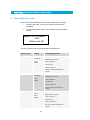
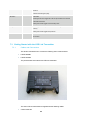
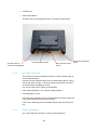
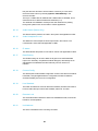
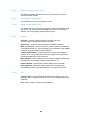
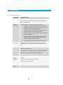
Users’ Manual
LDR Link User Manual
Page 1
Version 1.4
16 April 2009
Cobham Surveillance
Domo Products
11 Manor Court, Barnes Wallis Road, Segensworth,
Specifications subject to change without
notice PO15 5TH, England
Hampshire,
T: +44 (0)1489 566 750
F: +44 (0)1489 880 538
1
Table of Contents
1
Table of Contents........................................................................................... 2
2
Change History .............................................................................................. 3
3
About this Manual .......................................................................................... 4
4
Introduction .................................................................................................... 5
5
Warranty and Support.................................................................................... 6
5.1 Warranty Cover ................................................................................................ 6
6
Safety, Compliance and Approvals............................................................... 7
6.1 Safe Operating Procedures .............................................................................. 7
6.2 EMC / Safety and Radio Approvals .................................................................. 7
6.3 CE marking ...................................................................................................... 7
7
Getting Started and Basic Operation............................................................ 8
7.1 Which Model do I have?................................................................................... 8
7.2 Controls ........................................................................................................... 9
7.3 Getting Started with the LDR Link Transmitter ............................................... 10
7.4 Getting Started with the LDR Link Receive System........................................ 12
7.5 Powering on the System ................................................................................ 15
8
Advanced Operation .................................................................................... 18
8.6 Technical Overview........................................................................................ 18
8.1 SOLO4 System PC Controller Application Software....................................... 19
8.2 LDR Link Transmitter Control Application....................................................... 21
8.3 LDR Link Receiver Control Application........................................................... 25
9
Fault Finding ................................................................................................ 30
9.4 Fault Symptoms ............................................................................................. 30
10
LED Indicators .......................................................................................... 31
10.5
LDR Link TX ............................................................................................... 31
10.6
LDR Link RX ............................................................................................... 31
11
Technical Specifications .......................................................................... 32
11.7
Bandwidths and Bitrates ............................................................................. 32
11.8
SOLO4 Telemetry Transmitter .................................................................... 32
11.9
LDR Link Telemetry Receiver ..................................................................... 33
12
Connector Pin Outs .................................................................................. 34
12.10 LDR TX and RX - Power Amphenol ............................................................ 34
12.11 LDR TX and RX - Control Amphenol........................................................... 34
12.12 LDR TX and RX – Video Amphenol ............................................................ 34
13
Control Protocols...................................................................................... 35
13.13 RS232 Control – General Principles ........................................................... 35
13.14 Packet Structure Sending (from PC) ........................................................... 35
13.15 Packet Structure Reply (from controlled device) ......................................... 36
13.16 Telemetry System Command List ............................................................... 37
14
Typical Ranges of the LDR Link Product ................................................ 39
2
2
Change History
Version
Main Changes from Previous Version
Edited By
v1.0
Initial Release
MB
V1.1
Added comments to range tests
MB
V1.2
Added LDR Receiver, removed support for
Stream view software decoder
MB
V1.3
Added connector types
MB
V1.4
Correct error on data pin out
MB
3
3
About this Manual
This manual describes the operation of domo LDRLink (Low Data Rate Link)
wireless system. The manual is divided into three main sections.
•
Getting started and basic operation
This section describes to users how to deploy and use a LDR Link system.
•
Advanced operation
This section describes the operation of the system in more detail,
concentrating particularly on how to store and recall configurations, with use of
the PC Controller Application.
•
Technical reference
This section provides technical specification and control protocol data and will
be of interest to those integrating the LDR Link system into larger systems.
4
4
Introduction
This document constitutes the handbook for the LDR Link transmitter product,
and the ‘StreamView’ PC viewing application. This Handbook should be read
in conjuction with the SOLO4 Telemetry Handbook, for a complete system
view.
The domo LDR (Low Data Rate) transmitter is a digital video transmitter,
designed to operate over very long ranges. The LDR transmitter sends
informational quality video at reduced frame rates, compressed to very low
data rates (typically 30kb/s). This high level of compression and reduced data
rate, mean that the LDR transmitter, can send images over very long
distances. The LDR transmitter, occupies as little as 50KHz of bandwidth,
and can therefore be used more easily at UHF frequencies. Housed in a
robust water sealed enclosure and consuming only 3W, the LDR transmitter is
ideal for long term out door deployments.
Security is ensured with optional AES128/256 bit encryption.
The LDR transmitter is available in a variety of frequency bands from 300MHz
to 1GHZ, other frequencies are available on request.
The LDR transmitter will transmit images in a non line of sight environment up
to 2km, and line of sight to 20km depending on mode and frequency, further
range can be achieved with the optional clip-on booster PA.
LDR transmisions are received using the domo LDR receiver.
IMPORTANT NOTE
The LDR Link product range has been specifically designed for government security and law enforcement
users, the equipment will tune across frequencies that are only available to licensed government users.
Non-government users should employ the equipment restricted to the license exempt bands only typically
868-870MHz & 458MHz.
5
5
5.1
Warranty and Support
Warranty Cover
domo offers a 12 month standard product warranty. During this period, should
the customer encounter a fault with the equipment we recommend the
following course of action:
•
Check the support section of the website for information on that product and
any software/firmware upgrades. If fault persists;
•
Call our support line and report the fault. If fault persists and you are informed
to return the product please obtain an RMA number from the domo support
department, and ship the equipment with the RMA number displayed and a
description of the fault. Please email the support section the airway
bill/consignment number for tracking purposes.
•
If you have extended warranty provisions then domo will send an immediate
advance replacement to you. Under most circumstances this must be
returned once the fault item is repaired.
Depending on the nature of the fault domo endeavor to repair the equipment
and return it to the customer within 14 days of the item arriving at our
workshops.
Obviously it is impossible to cater for all types of faults and to manage 100%
replacement part availability, and delays are sometimes inevitable. This is
why domo recommend that its customers take out an extended warranty
(which includes advanced replacement of faulty items), and/or hold a basic
level of spare parts, which can be held by domo on the customer’s behalf.
Please contact domo for details of packages that can be tailored to meet your
individual needs, whether they are service availability, technical training, local
geographic support or dedicated spares holdings.
6
6
6.1
6.2
Safety, Compliance and Approvals
Safe Operating Procedures
•
Ensure that the power supply arrangements are adequate to meet the stated
requirements of each LDRLink product.
•
Operate within the environmental limits specified for the product.
•
Do not subject the indoor equipment to splashing or dripping liquids.
•
Only authorized, trained personnel should open the product. There are no
functions that required the User to gain access to the interior of the product.
EMC / Safety and Radio Approvals
The equipment has been designed to meet and has been tested against the
following harmonized EMC and safety standards:
6.3
•
EN 301 489-1 & EN 301 489-5
•
EN 61000-3-2:2000
•
EN 61000-3-3:1995
•
EN 55022:1998, Class B
•
EN 61000-4-2:1995
•
EN 61000-4-3:1996
•
EN 61000-4-4:1995
•
EN 61000-4-5:1995
•
EN 61000-4-6:1996
•
EN 61000-4-11:1994
•
EN 60950:2000
CE marking
The CE mark is affixed to the LDRLink product, and the CE Declaration of
Conformity, as well as the technical file are available on request.
7
7
Getting Started and Basic Operation
7.1
Which Model do I have?
Each unit in the domo SOLO4 product range is marked with two panels.
•
Product Code Panel. Give product code and manufacturers
information.
•
CE and Serial Number Panel. Gives CE mark and product serial
number.
domo LDRTX-086087
UHF
Made in the UK
The domo product code can be referenced in the table below.
Product Code
Product
Accompanying items
LDRTX-086087
LDR Link
Cables:
Transmitter.
868 to
868MHz Omni Antenna
Control Cable 2m
870MHz
DC Power 2m
Video In Cable 2m
CD with operating software and
manual
LDRTX-045045
LDR Link
Cables:
Transmitter
458MHz Omni Antenna
457 to
Control Cable 2m
458MHz
DC Power 2m
Video In Cable 2m
CD with operating software and
manual
LDRRX-086087
LDR Link
Cables:
Receiver
868MHz Omni Antenna
868 to
Control Cable 2m
870MHz
DC Power 2m
Video Out Cable 2m
CD with operating software and
manual
8
LDRRX-045045
LDR Link
Cables:
Receiver
458MHz Omni Antenna
457 to
Control Cable 2m
458MHz
DC Power 2m
Video Out Cable 2m
CD with operating software and
manual
7.2
Controls
LDR Link transmitters and receivers are equipped with a standard LED (Light
Emitting Diode) and push button panel. The panel is as depicted below, and
the buttons and LEDs have meanings as explained in the table.
RF
ALARM
MODE
RF
1
2
3
4
5
6
7
8
CONFIG
LED / Button
Colour
Meaning / Use
Alarm LED
Red
When lit indicates alarm or fault condition on equipment. (Not Currently
Supported)
Front Panel Lock
Yellow
When lit indicates front panel is locked
Green
Transmitter:
LED
RF LED
When lit indicates RF output is active.
When blinking indicates transmitter is operating in discontinuous mode
and is not currently transmitting (waiting for data). (should not be used in
LDRL)
Receiver:
When lit indicates receiver has signal lock.
LED 1 to 8
Green
Indicates which of the eight stored configurations is currently selected.
Signal Strength
Green
Transmitter:
LED’s
Indicates output power level 5,10,15 & 20 dBm.
9
Receiver:
Indicates received signal quality.
RF Button
-
Transmitter:
Pressing the RF button toggles the units RF output between OFF and ON.
Transmitter & Receiver:
Holding down button toggles unit into standby mode.
Config Button
-
The config button when pressed selects the next configuration from
memory.
Holding down button toggles front panel lock.
Mode Button
-
Transmitter:
No Function
7.3
Getting Started with the LDR Link Transmitter
7.3.1
Cables and Connections
This section describes how to connect the following domo model numbers.
•
LDRTX-086087
•
LDRTX-045045
The picture below shows the domo LDR Link transmitter.
The domo LDR Link transmitter is supplied with the following cables.
•
Control Cable 2m
10
•
DC Power 2m
•
Video input Cable 2m
The domo LDR Link transmitter should be connected as shown below.
Connect to PC for
control and configuration
7.3.2
Connect to video source
Connect to DC power
source
Antenna Connected as
shown
DC Power Connection
The LDR Link unit can be powered from either a nominal 12V DC supply or
from an external battery.
Connect the 3 pin Amphenol cable to the connector labeled ‘DC IN’ , taking
care to align the connectors. Connect the banana connectors on the other
end of the cable to a suitable DC source.
The 12V DC input has the following characteristics:
•
Input Voltage Range 6V to 16V, reverse voltage protected.
•
Power dissipation <3.5W
domo can supply optional AC to DC converter blocks to power the LDR Link
units, please contact domo if these are required
If the unit is in standby press and hold down the RF button to power up the
unit.
7.3.3
Control Connections
The 7 way Amphenol connection is used for control interfacing.
11
The control cable is used for Control, and is used to connect the LDR Link unit
to a PC with a suitable RS232 control interface for connection to the domo PC
GUI application or an embedded control application.
7.3.4
Video
Connect the video input to the Amphenol connector labeled ‘Video In’.
Connector
Signal
Video BNC (on cable)
75 ohm composite video source, PAL or NTSC
software selectable
Typically the video source will be a small colour or black and white CCD
camera.
7.3.5
Antennas
The unit is supplied with 868MHz (or 458MHz) omni-directional flexible
antennas as standard. These should be screwed directly to the panel mount
TNC RF Out connector. Care should be taken to not over tighten the
antenna. It is recommended that the transmit antenna should be connected
directly to the unit and not via a cable. Any cable in this position will reduce
the range performance of the equipment.
Important Note: The supplied antennas are dipole antennas and do not require a ground plane. Users might
wish to use other antennas, such as directional antennas for greater range.
Additional antennas may be ordered from domo. For longer range, more specialized antennas such as Yagis
can be supplied.
7.3.6
Installation notes
The domo LDR Link transmitter is supplied in a rugged chassis with mounting
holes for ease of integration. It is designed for simple integration into any
system.
The LDR Link transmitter can be mounted in an outdoor situation. In an
outdoor situation care should be taken to mount the unit with the connectors
pointing downwards. The cable connectors must be protected by the drip
ledge.
7.4
Getting Started with the LDR Link Receive System
7.4.1
Cables and Connections
This section describes how to connect the following domo model numbers.
12
•
LDRRX-086087
•
LDRRX-045045
The picture below shows the domo LDR Link receiver.
The domo LDR Link receiver is supplied with the following cables.
•
Control Cable 2m
•
DC Power 2m
•
Video input Cable 2m
The domo LDR Link receiver should be connected as shown below.
13
Connect to PC for
control and configuration
7.4.2
Connect to video
monitor
Connect to DC power
source
Antenna Connected as
shown
DC Power Connection
The LDR Link unit can be powered from either a nominal 12V DC supply or
from an external battery.
Connect the 3 pin Amphenol cable to the connector labeled ‘DC IN’ , taking
care to align the connectors. Connect the banana connectors on the other
end of the cable to a suitable DC source.
The 12V DC input has the following characteristics:
•
Input Voltage Range 6V to 16V, reverse voltage protected.
•
Power dissipation <3.5W
domo can supply optional AC to DC converter blocks to power the LDR Link
units, please contact domo if these are required
If the unit is in standby press and hold down the RF button to power up the
unit.
7.4.3
Control Connections
The 7 way Amphenol connection is used for control interfacing.
The control cable is used for Control, and is used to connect the LDR Link unit
to a PC with a suitable RS232 control interface for connection to the domo PC
GUI application or an embedded control application.
7.4.4
Video Output
Connect the video output to the Amphenol connector labeled ‘Video Out’.
14
Connector
Signal
Video BNC (on cable)
75 ohm composite video source, PAL or NTSC
software selectable
Typically the video monitor will be PAL or NTSC monitor.
7.4.5
Antennas
The unit is supplied with 868MHz (or 458MHz) omni-directional flexible
antennas as standard. These should be screwed directly to the panel mount
TNC RF IN connector. Care should be taken to not over tighten the antenna.
It is recommended that the transmit antenna should be connected directly to
the unit and not via a cable. Any cable in this position will reduce the range
performance of the equipment.
Important Note: The supplied antennas are dipole antennas and do not require a ground plane. Users might
wish to use other antennas, such as directional antennas for greater range.
Additional antennas may be ordered from domo. For longer range, more specialized antennas such as Yagis
can be supplied.
7.4.6
Installation notes
The domo LDR Link receiver is supplied in a rugged chassis with mounting
holes for ease of integration. It is designed for simple integration into any
system.
The LDR Link receiver can be mounted in an outdoor situation. In an outdoor
situation care should be taken to mount the unit with the connectors pointing
downwards. The cable connectors must be protected by the drip ledge.
7.5
Powering on the System
All external connections to the LDR Link System should be made, as
described in the previous sections, before proceeding to power on the system.
7.5.1
Applying power to the LDR Link Receiver
On powering the LDR Link receiver, one of the eight green configuration LEDs
on the control panel will light (which one depends on which configuration was
active when the receiver was switched off). The red Alarm LED may light if
the receiver is unable to lock to a signal.
If none of the LEDs on the control panel light then the Receiver may be in
standby mode. If this is the case then press, and hold the RF button for more
than one second.
15
7.5.2
Applying power to the LDR Link Transmitter
When powering the LDR Link transmitter directly from a DC source, the
following will be observed.
If none of the LEDs on the control panel light then the transmitter may be in
standby mode. If this is the case then press, and hold the RF button for more
than one second.
One of the eight green configuration LEDs on the control panel will light (which
one depends on which configuration was active when the transmitter was
switched off).
The alarm LED may be lit, typically if there is a serious error with the unit
(video input lock alarm is not currently supported).
7.5.3
Switching on the RF
On the transmitter unit control panel, press the RF button briefly until the RF
LED lights. This indicates that the RF output is active, and that the unit is
transmitting.
If the receiver is able to receive the transmitted signal, the receiver RF LED
will light indicating receiver lock, and the receiver ALARM LED should go out.
The signal strength LEDs will indicate the received signal quality.
Data and audio signals will be presented automatically at the receiver outputs.
NOTE:
The signal quality may be degraded if the units are placed too close together and the signal is too
strong. Move the units further apart.
7.5.4
Changing Configuration
domo LDR Link equipment features eight user selectable and programmable
configurations. By default, all 8 configurations are available to the user. The
configuration that is currently active is indicated by which of the eight
configuration LEDs is lit on the control panel. Pressing the ‘CONFIG button on
the control panel of any domo LDR Link equipment will select the next
configuration in order.
On the LDR Link transmitters, changing a configuration turns off the RF output
to prevent accidental transmission and potential interference. The RF output
must manually be re enabled once the user is confident that the correct
configuration has been selected.
Modifying the default configurations is done from the PC control application,
as described in the section on Advanced Operation.
7.5.5
Front Panel Lock
Pressing and holding down the CONFIG button for more than 1 second will
toggle the front panel lock feature. This prevents accidental key presses on
the panel affecting the unit’s operation.
16
7.5.6
Standby
Any of the LDR Link transmitters and receivers can be placed in a low current
consumption standby mode by pressing and holding the RF button for one
second. The LEDs will go out indicating that the unit is in standby mode.
Pressing and holding the RF button for one second brings the unit back out of
standby mode.
7.5.7
Achieving a Video Link
Once an RF connection has been successfully achieved, then a video link can
be formed.
With a suitable camera source connected to the LDR Transmitter, video
should be displayed on the monitor connected to the video output of the LDR
Receiver.
The LDR system is a very low bitrate system and sends informational quality
video. The LDR system can be optimized by users to send different video
frame rates and resolutions.
Frame Rate Options: 2, 5 or 12 F/s
Resolution Options: CIF (352 * 288 pixels) or QCIF (176 * 144 pixels)
Typically domo recommends the following settings.
50KHz Bandwidth:
2 Frames/s CIF
75 and 100KHz Bandwidth:
5 Frames/s CIF
125KHz Bandwidth:
12 Frames/s CIF
17
8
Advanced Operation
8.6
Technical Overview
8.6.1
OFDM Transmission
The LDR Link transmitter and receiver utilise Orthogonal Frequency Division
Multiplex for modulation. This modulation scheme provides excellent protection
against multi-path and interference. The system employs interleaving and two
levels of error correction (Low Density Parity Codes & BCH decoding) to further
enhance performance.
The modulator channel width may be set in multiples of 25kHz. This determines
spectrum bandwidth and the gross bit rate of the system in multiples of
14.7Kbits/s. The bandwidth of the modulated signal is roughly 4/5 of this
channel spacing. The default mode is 75KHz.
A combination of IF and digital filtering provide receiver selectivity. The
demodulator allows the user to read various parameters such as the input signal
level, the signal to noise ratio and raw error rates via the remote control
interface.
8.6.2
Video Compression
The LDR Link operates a sophisticated MPEG4 encoder operating at very low
bitrates. The encoder is capable of operating in two resolutions 352 * 288 or
176*144, and at different frame rates 12, 5 or 2 frames per second. The unit is
defaulted to 352 * 288 at 5 frames per second.
8.6.3
AES Encryption
The LDR Link module supports both AES128 and AES256 encryption. These
provide a very secure method of handling data and audio. Both AES128 and
AES256 are licensable features. To enable encryption a 32 digit hex key, (or in
the case of AES256 two 32 digit hex keys) must be written to the unit. The
scrambling mode must then be set to the appropriate mode of operation.
The AES128+ and AES256+ options in the receiver can be used to prevent the
receiver accepting unscrambled streams which may be useful in some
applications. Note that having mismatched keys between Tx and Rx may allow
a small amount of encrypted data to pass through the data pipes.
AES128 and AES256 are licensable features and are only supported in certain
countries.
18
8.1
SOLO4 System PC Controller Application Software
Advanced control of the SOLO4 system is available by using PC control
applications.
Typically users may want to customize the default configurations to control
settings such as frequency, scrambling keys, modulation parameters etc.
•
Both the SOLO4 Telemetry Transmitter and Receiver are controlled with the
same application telemetry_ctrl.exe which auto-detects the type of unit it is
connected to.
Note that exact file names may change as software version information is a part of domo file names.
A PC is required with two RS232 Serial COM ports to control both a
transmitter and receiver simultaneously. Where changes are to be made to
either a transmitter, or a receiver, at different times, a PC with a single RS232
Serial COM part can be used.
Installation the two control programs is as simple as copying them from the
CD to a suitable location on the PC. No install shield routine is launched. Note
that the controllers generate their own log and initialisation files, so it is best to
create a dedicated directory for these applications, perhaps with links to the
applications from the desktop of the PC.
Use the supplied cables to connect the chosen COM port(s) of the PC to
unit(s) to be configured.
Launch each application in turn by double clicking or using the run command.
Connection with a SOLO4 Telemetry product should be automatic, but the
user can force selection of the correct COM port using the drop down,
followed by the “Connect” button.
Errors such as the following may appear during the connection process if the
PC is unable to automatically ascertain which unit is connected to which COM
port.
•
Error attempting to read invalid address
•
Error has occurred during polling, polling has been disabled
19
Changes can be made to the unit configuration using the drop down and data
entry fields.
Changes are only applied to the unit when the “Apply New Values” button is
clicked.
Current values, as running in the unit, can be read using the “Refresh” button.
Parameters that are status information only appear in greyed in the
application.
Further engineering and configuration controls can be found within the
“Options” and “File” drop down menus in the application title bars.
20
8.2
LDR Link Transmitter Control Application
Important – version 1.3 and above of the telemetry controller should be
employed with the LDRL transmitter.
8.2.1
Modulation Output
This control is used to turn on and off the RF output. After a configuration
change, the output always reverts to OFF.
8.2.2
TX Duty Cycle
This determines whether the transmitter operates in continuous or
discontinuous mode. Should be set to Continous
8.2.3
Modulator Constellation
The COFDM mode can be changed between QPSK and 16QAM. QPSK is
the default mode and will give the strongest most rugged RF link performance.
Selecting 16QAM reduces the link performance by 5.5dB but doubles the link
data throughput.. Should be set to QPSK
21
8.2.4
Output Frequency (MHz)
The transmit frequency can be changed by entering the new desired
frequency in this field. Values outside the range supported by a particular
transmitter type will be rounded to the highest of lowest supported frequency
as appropriate.
The transmit frequency can be set in step sizes of 12.5kHz. In License exempt
mode of operation the frequency, bandwidth power level and TX duty cycle
will be adjusted accordingly.
8.2.5
Output Power Attenuation
This sets the output attenuation in dB. 0dB corresponds to a nominal
maximum level of 100mW.
8.2.6
Modulator Channel Width
Sets the modulator channel width in 25kHz steps. The width of the spectrum is
about 4/5 of this channel width. Should be set to 75KHz. Typically only 50,
75, 100 and 125KHz are supported.
8.2.7
Data Enable/Parity
With this control the user can select whether the transmitter passes serial
RS232 data across the RF link to the receiver. A choice of no parity, even &
odd parity is selectable.
8.2.8
Data Baud Rate
In LDRL mode this field is for information only.
Bandwidth 50KHz = Baudrate 19K2
Bandwidth 75KHz = Baudrate 38K4
Bandwidth 100KHz = Baudrate 38K4
Bandwidth 125KHz = Baudrate 56K6
8.2.9
Scrambling
If the AES scrambling option has been purchased for the SOLO4 Telemetry
system in use, then it is possible to encrypt the link. Scrambling must be
enabled at the transmitter by selecting either AES128 or AES 256 in the
scrambling field. At this point the user will need to ensure that the correct key
is in use and this is done by using Options / Write AES Key.
The key is a 128bit key for AES128 and a 256bit key for AES256 and is
entered as either 32 or 64 ASCII hexadecimal characters (0..F).
8.2.10
Audio Encoder
The Audio can be enabled with this control. Audio is off by default, and there
are 2 mono modes available to the user. 24Kbits/s toll quality and 32Kbits/s
telephone quality may be selected both at 8KHz sampling rate. Some bit-rates
will not support audio. Should be OFF
22
8.2.11
Audio Input Level
This control is used to define the audio gain to be applied to the audio input
signal. 0dB is used for line level audio and various options up to 48dB of gain
can be applied for microphone inputs.
8.2.12
Enable RC servo control
Enables the 2 channel joystick and servo interfaces. Not applicable to LDR
Link.
8.2.13
IP Enable
Enables the IP interface for the Netstream unit. Not applicable to LDR Link.
8.2.14
IP/Data Routing
The IP/data routing can be set to allow the IP pipe to use the RS232 data
input on the Telemetry unit (default is RS232 data pipe). Alternatively the IP
data between the Netstream and the Telemetry unit can use the TTL
interface. Not applicable to LDR Link.
8.2.15
Gross Bit Rate (Status Only)
This give an indication of the channel bit rate available. This can be useful in
calculating data throughput.
8.2.16
Current Config
This field reports the last loaded configuration number. Note that for the SOLO
transmitter, changes applied after the configuration has been loaded are
saved immediately into the current configuration.
8.2.17
Line Standard
Auto-detected video line standard on the LDR Transmitter, PAL or NTSC.
8.2.18
Resolution and Frame Rate
The LDR system is a very low bitrate system and sends informational quality
video. The LDR system can be optimized by users to send different video
frame rates and resolutions.
Frame Rate Options: 2, 5 or 12 F/s
Resolution Options: CIF (352 * 288 pixels) or QCIF (176 * 144 pixels)
Typically domo recommends the following settings.
50KHz Bandwidth:
2 Frames/s CIF
23
8.2.19
75 and 100KHz Bandwidth:
5 Frames/s CIF
125KHz Bandwidth:
12 Frames/s CIF
Video Lock
Not currently supported
8.2.20
Unit Address
This is the unit address of the unit being controlled.
8.2.21
Software Version (Status Only)
This status information describes the version of the software running the
SOLO4 transmitter product.
8.2.22
FPGA Version (Status Only)
This information is for domo engineering use only.
8.2.23
Serial Number (Status Only)
This status information is the electronic serial number of the transmitter PCB.
This number can be exchanged with domo to purchase extra licensable
features, such as upgrades to support AES encryption.
8.2.24
Options
Timeouts – access to change timeouts used during the serial
communications between the unit and the controller.
Engineering – access to further diagnostic and calibration features.
Write License Code – open box for entering license codes for the activation
of licensable features (e.g. AES scrambling) in the transmitter. Contact domo
for support in applying new licenses as required.
Change RS232 address – prompts the user to change the units RS232
address, which can be useful when connecting multiple units together via a
multi drop RS485 bus for control purposes.
Write AES Key – opens a dialogue box for entering a 128bit and 256bit AES
scrambling key, as 32 ASCII hexadecimal characters (0…F)
Restore Defaults – restores factory default settings in the transmitter.
8.2.25
File
Change Logfile – opens a standard Windows file save dialogue box which
allows the user to change the path and name of the log file generated by the
application.
Exit – exits the SOLO4 receiver control application
24
8.3
LDR Link Receiver Control Application
Important – version 1.3 and above of the telemetry controller should be
employed with the LDRL transmitter.
8.3.1
Input Frequency
The receive frequency can be changed by entering the new desired frequency
in this field.
8.3.2
Demodulator Channel Width
Sets the demodulator channel width in 25KHz steps. This must match the
modulator channel width. For LDRL 50, 75, 100 and 125KHz are applicable.
8.3.3
Demodulator Constellation (Status Only)
This field displays the COFDM constellation that is being demodulated at the
receiver. In normal operation this will match that selected at the transmitter.
25
8.3.4
Input LNA gain
This allows selection of the input gain at the front end of the demodulator. Low
gain mode improves the blocking on the input by about 10dB but has a similar
reduction on sensitivity.
8.3.5
Demod Lock Status (Status Only)
This indicates whether the demodulators are successfully locked to the RF
signal.
8.3.6
Input SNR (Status Only)
For each IF input, the SNR (Signal to Noise Ratio) is reported. Values in the
order of 18dB to 22dB represent strong received signals, whilst values in the
order of 5dB represent poor received signals which will likely give rise to
decoding errors.
8.3.7
Input Level (Status Only)
This figure indicates the received signal level at the two receiver inputs.
Normal Operation will occur when the input level is between –25 and –115
dBm. Signals greater than –25 may be too powerful and cause damage.
Signal less than -115dBm may be too weak and cause data loss (typical link
failure will occur between –118dBm depending on mode). The input level may
also increase when the antennas are connected and there is no transmission.
This indicates the presence of interference.
8.3.8
BER Pre-LDPC (Status Only)
This is the raw error rate prior to the error correction techniques having been
applied in the receiver.
8.3.9
BER Post-LDPC (Status Only)
This is the error rate before the BCH decoder.
8.3.10
Packet Error Rate (Status Only)
This is a measure of the number of un-correctable errors in the system. Any
value other than 0 with cause loss of data, break up of audio and is a good
indication of link failure.
8.3.11
Data Status (Status Only)
This field shows the presence of data in the system by indicating the parity of
the data or none if no data is present.
8.3.12
Data Baud Rate (Status Only)
This field reports the baud rate of the RS232 serial data component that is
present and selected in the stream.
8.3.13
Scrambling
If the AES scrambling option has been purchased for the SOLO4 system in
use, then it is possible to encrypt the link. Descrambling must also be enabled
at the receiver by selecting AES128 or AES256 in the descrambling field. At
26
this point the user will need to ensure that the correct key is in use at the
receiver and this is done by selecting Options / Write AES Key in the
receiver controller.
The key is a 128bit value for AES128 and a 256bit value for AES256, and is
entered as 32 or 64 ASCII hexadecimal characters (0...F).
The AES128+ and AES256+ modes prevent clear streams from passing
through the system which can be useful in certain applications.
8.3.14
Audio Status (Status Only)
This field shows the presence of audio in the system. Not applicable to LDRL.
8.3.15
Audio Headphone Level
This allows the user to adjust the audio output level in the receiver. The
nominal level is set to 0dB. Not applicable to LDRL.
8.3.16
IP status
This field indicates the presence of IP data on the link. Not applicable to LDRL.
8.3.17
Data Routing
The IP/data routing can be set to allow the IP pipe to use the RS232 data
input on the Telemetry unit (default is RS232 data pipe). Alternatively the IP
data between the Netstream and the Telemetry unit can use the TTL
interface.
8.3.18
Current Config
This field reports the last loaded configuration number. Note that for the SOLO
transmitter, changes applied after the configuration has been loaded are
saved immediately into the current configuration.
8.3.19
Line Standard
The LDRL decoder does not auto detect line standard, therefore this needs to
be set to reflect the input camera line standard, either PAL or NTSC.
8.3.20
Decoder Lock
This information field indicates the status of the MPEG4 decoder, it should be
locked for normal operation.
8.3.21
Unit Address
This is the unit address of the unit being controlled.
27
8.3.22
Software Version (Status Only)
This status information describes the version of the software running the
SOLO4 transmitter product.
8.3.23
FPGA Version (Status Only)
This information is for domo engineering use only.
8.3.24
Serial Number (Status Only)
This status information is the electronic serial number of the transmitter PCB.
This number can be exchanged with domo to purchase extra licensable
features, such as upgrades to support AES encryption.
8.3.25
Options
Timeouts – access to change timeouts used during the serial
communications between the unit and the controller.
Engineering – access to further diagnostic and calibration features.
Write License Code – open box for entering license codes for the activation
of licensable features (e.g. AES scrambling) in the transmitter. Contact domo
for support in applying new licenses as required.
Change RS232 address – prompts the user to change the units RS232
address, which can be useful when connecting multiple units together via a
multi drop RS485 bus for control purposes.
Write AES Key – opens a dialogue box for entering a 128bit and 256bit AES
scrambling key, as 32 ASCII hexadecimal characters (0…F)
Restore Defaults – restores factory default settings in the transmitter.
Polling Enabled – selecting this option makes the control application
automatically refresh the data presented to the user every few seconds.
8.3.26
File
Change Logfile – opens a standard Windows file save dialogue box which
allows the user to change the path and name of the log file generated by the
application.
Exit – exits the SOLO4 receiver control application
28
29
9
9.4
Fault Finding
Fault Symptoms
Symptom
Suggested Action
No RF Link
Check a suitable transmitter RF transmitter is active, both units on correct
frequency, and correct bandwidth settings with antennas connected. Ensure
there is no interfering signal.
Poor link
performance
Poor performance of the link can occur for the following reasons.
•
Interference. Should an interfering RF signal occur on the same
frequency the performance of the link will be affected. Remove the
interferer e or move to an alternative frequency.
•
Unsuitable antennas, or out of band antennas. See the antenna
sections for guidance on antenna selection and use.
•
Reduced transmit power, ensure that the attenuation setting on the
transmitter is appropriate.
•
Receive antenna positioning, were possible mount the receive
antennas away from other objects, unobstructed and away from
any electronics likely to generate interference.
•
Loss of data
No Diversity operation. Ensure both antennas are operational.
Check link performance, data cables are in good condition and correct use of
Xon/Xoff flow control. In discontinuous mode check ‘Ton’ period is not too
short.
No Video
Check RF Link is functioning (see above)
Check video input is connected
Check cable from LDR Link Receiver to PC is connected and is ‘Data Cable’
Check correct ‘Comm port’ is selected on StreamView software
No Decoder
Indicates that the LDRL receiver can not see a valid stream from the LDRL
Lock
transmitter.
displayed at
Receiver
Check that RF lock has been achieved (see above)
Check that the camera is connected.
Unstable
Check the LDRL decoder line standard matches the camera (PAL / NTSC)
Video
30
10 LED Indicators
10.5 LDR Link TX
LED Condition
Meaning
Red ALARM LED lit permanently
Unit is faulty / incorrect software loaded
RF LED blinking
Unit in discontinuous mode, RF inactive,
RF must be continuous for LDRL.
RF LED lit
RF output active
RF LED not lit
RF output inactive
Single CONFIG LED lit
Indicates selected config
Front Panel Lock
Indicates front panel locked
RF Bar Graph
RF output level
No LEDs lit
Unit in standby or Off
10.6 LDR Link RX
LED Condition
Meaning
Red ALARM LED lit permanently
Unit is faulty / incorrect software loaded
RF LED off
No RF signal lock
RF LED on
RF signal lock
Single CONFIG LED lit
Indicates selected config
Front Panel Lock
Indicates front panel locked
RF Bar Graph
RF signal quality
No LEDs lit
Unit in standby or Off
31
11 Technical Specifications
11.7 Bandwidths and Bitrates
Channel
Spacing
Channel
Bandwidth
User Bitrate
(QPSK)
25 kHz
20 kHz
Not Supported
50 kHz
40 kHz
29 kbits/s (19K2
baud of video)
75 kHz (default)
60 kHz
44 kbits/s
(default) (38K4
baud of video)
100 kHz
80 kHz
58 kbits/s (38K4
baud of video)
125 kHz
100 kHz
73 kbits/s (56K6
baud of video)
150 kHz
120 kHz
Not Supported
175 kHz
140 kHz
Not Supported
200 kHz
160 kHz
Not Supported
225 kHz
180 kHz
Not Supported
250 kHz
200 kHz
Not Supported
275 kHz
220 kHz
Not Supported
300 kHz
240 kHz
Not Supported
11.8 SOLO4 Telemetry Transmitter
Operating Frequency
458MHz or 868-870MHz (ISM)
Modulation
Channel Bandwidth
Maximum output power
Default QPSK 1/16 Guard
105 carrier OFDM QPSK/16QAM 1/16 guard
Default 75KHz
25,50,75,100,125..300KHz
20,40,60,80,100..240KHz
100mW
Power Supply Voltage
Power dissipation
5.5-18V
<3W
RS232 data rates
RS232 parity
1200,2400,4800,9600,19200,38400,57600,115200
None, Even, Odd with Xon/Xoff flow control where
necessary
Video
Default 5 frames per second, 30kb/s, 352*288
Channel Spacing
32
Frame Rate 12 or 5 or 2 frames/s
Resolution 352* 288 or 176*144
11.9 LDR Link Telemetry Receiver
Operating Frequency
458MHz or 868-870MHz (ISM)
Modulation
Default QPSK
Channel Spacing
105 carrier OFDM QPSK/16QAM 1/16 guard
Default 75KHz
Image rejection
Adjacent channel rejection
Error correction/detection
25,50,75,100,125KHz, (and
150,175,200,225,250,275,300KHz with wider IF filter)
2 way diversity MRC
< -113dBm@100KHz 16QAM, -118dBm@100KHz QPSK,
-121dBm@50KHz,
> 52dB (10.7MHz IF Hi-Side LO)
> 45dB
2112 bit rate ½ soft LDPC, 968/1056 BCH
Power Supply Voltage
Power dissipation
5.5-18V
<3W
RS232 data rates
Default 38k4
1200,2400,4800,9600,19200,38400,57600,115200
None, Even, Odd
Antenna
Input sensitivity
RS232 parity
33
12 Connector Pin Outs
12.10 LDR TX and RX - Power Amphenol
Amphenol - 3 way pin part no.62GB-57A08-33PN
Pin A:
12V
Pin B:
GND
Pin C:
unused
12.11 LDR TX and RX - Control Amphenol
Amphenol - 7 way socket part no.62GB-57A10-07SN
Pin A:
Unused
Pin B:
RS232 data In
Pin C:
unused
Pin D:
Unused
Pin E:
RS232 data Out
Pin F:
GND
Pin G: Unused
12.12 LDR TX and RX – Video Amphenol
Amphenol - 4 way socket part no.62GB-57A08-04SN
Pin A:
Power (voltage out)
Pin B:
GND
Pin C:
Video GND (screen)
Pin D:
Video Input (transmitter) Video Output (receiver)
34
13 Control Protocols
The following section describes the control protocol employed on the RS232
link for controlling the LDR Link transmitters and receiver equipment.
Connection details are detailed in previous sections.
Note that only features that are licensed for use in the LDR Link units can be controlled. The protocols listed
here cover all possible features. Attempting to activate an unlicensed feature will simply result in the
command being ignored by the LDR Link unit.
TX commands sent to an RX unit and visa-versa will be acknowledged have no effect.
13.13 RS232 Control – General Principles
The physical interface is RS232 but this can be converted to RS 485 with an
external adapter where multiple units are controlled over one RS 485 bus.
Normal operation involves sending a packet from the control device (normally
a PC) to the device being controlled. If the packet satisfies an address integrity
check, then the controlled device will action the command and send a reply.
For compatibility with modems an ASCII style protocol is used.
Ports are set for 9600 Baud, 8 bits, No parity, 1 stop
13.14 Packet Structure Sending (from PC)
ASCII
STX
0-9
R
misc
I
ABC
;
PQR
;
X
ETX
Value
02h
30h-39h
20h-7Eh
Start byte
4 byte unit address. In range 0-9999
1 byte command type. r read, w write or m
20h-7E
20h-7Eh
3Bh
20h-7Eh
3Bh
20h-7Eh
03h
1 byte indicator of internal data block
Command –three byte mnemonic
Separator
Data –Optional, variable length
Separator
Sum Check
End byte
35
13.15 Packet Structure Reply (from controlled device)
ASCII
STX
0-9
Z
PQR
;
X
ETX
Value
02h
30h-39h
20h-7Eh
20h-7Eh
3Bh
20h-7Eh
03h
Start byte
4 byte unit address. In range 0-9999
Status BYTE
Data –Optional, variable length
Separator
Sum Check
End byte
The Sum check byte is the summation of all bytes in the packet, not including
the start and end bytes. Higher order bytes are ignored and the final byte
result is modified to prevent ASCII control characters being sent. Bit 7
(highest) is forced high.
Status byte will indicate command performed OK, or indicate an error.
ASCII
Meaning
1
All OK
E
General error, Command could not be actioned
Typically E will be returned if the message is formatted incorrectly (separators
in wrong place) or if commands are in upper case, or if commands do not
match against the allowed list of commands, or if the checksum is wrong.
Addresses in the range 0001 to 9998 are for general use. Address 0000 is
reserved and 9999 is a broadcast address. i.e. any device will reply to this
address. Its reply will contain its own specific address.
All data in the transmitter and receiver is stored as one of 5 data types,
Double, String, List, Integer or HexInteger. The data type dictates the
contents of the data section of the reply.
•
List – 1 byte for sending. Value is hexadecimal coded as ASCII. 2 byte reply.
Reply represents index into original choice list. e.g. Reply 02 indicates entry 2
in original list.
•
Double - variable length. Reply always contains decimal point and 4 decimal
places. Can have 1 to 3 digits before decimal.
•
Integer - 6byte reply. integer value with stuffed with preceding zeros. e.g. GOP
reply 000012 = GOP length 12
•
String - Variable length. Reply is string excluding null terminator
•
HexInteger – 8byte Hex reply
36
13.16 Telemetry System Command List
Comm
Description
Tx/Rx
RW
Type
Comments
Default
gadd
gser
gver
gfpg
gdef
glic
gsle
glod
gtyp
gau2
gfpl
gstt
Unit address
Unit serial number
Software version number
FPGA version number
Restore defaults
License code
Sleep
Config number
Unit Type
Set remote command
Front panel lock
Enable status display
TxRx
TxRx
TxRx
TxRx
TxRx
TxRx
TxRx
TxRx
TxRx
Tx
TxRx
Rx
RW
R
R
R
W
W
RW
RW
R
RW
RW
RW
Integer
Hex
String
Hex
Integer
Hex
Integer
Integer
Integer
Integer
Integer
Integer
9999 - broadcast address
2-tx,3-rx
0 - active, 1 - sleep mode
1-8 config
bit0=0 Tx, bit 0=1 Rx
1 - allow remote commands, 0 = off
0 - unlocked, 1 = locked
0 - disabled, 1 - enabled @ 9600 baud
0
1
oout
omod
odut
ofre
opwr
onrt
omux
Modulator output
Modulator constellation
TX duty cycle
Output frequency
Output power attenuation
Modulator Channel Width
Gross TX bit rate
Tx
Tx
Tx
Tx
Tx
Tx
Tx
RW
RW
RW
RW
RW
RW
R
Integer
Integer
Integer
Float
Float
Integer
Float
0 - Off, 1 - On
0 - QPSK, 1 - 16QAM
0 - Continuous, 1 - Discontinuous operation
MHz
dB
1 - 25KHz ... 5 - 125KHz
Kbits/s
0
0
0*
869.45*
0*
4*
cflo
cfhi
cplv
cton
ctof
Minimum operating frequency
Maximum operating frequency
Power level calibration level
TX on timeout
TX off timeout
TxRx
TxRx
Tx
Tx
Tx
RW
RW
RW
RW
RW
Float
Float
Float
Integer
Integer
MHz
MHz
dB
Timeout before data is sent in discontinuous mode
Timeout before Tx turns off in discontinuous mode
868
870
dpid
dinp
dbau
drem
Tx Data PID
Tx Data Enable
Tx Data Baudrate
Tx Aux Control PID
Tx
Tx
Tx
Tx
RW
RW
RW
RW
Integer
Integer
Integer
Integer
0x10-0x17
0 - off, 1 - no parity, 2 - even parity, 3 - odd parity
0 - 1200,2400,4800,9600,19200,38400,57600,115200
0x28-0x2f
0x10
1
6
0x28
1fre
1nrt
1lna
1loc
1snr
1mer
1ina
1inb
1pre
1pos
1pkt
1mod
Input Frequency
Demodulator Channel Width
Input LNA gain
Demod Lock
Demod SNR A
Demod SNR B
Input level A
Input level B
Pre-LDPC error rate
Post-LDPC error rate
Packet error rate
Demodulator constellation
Rx
Rx
Rx
Rx
Rx
Rx
Rx
Rx
Rx
Rx
Rx
Rx
RW
RW
RW
R
R
R
R
R
R
R
R
R
Float
Integer
Integer
Integer
Float
Float
Float
Float
Integer
Integer
Integer
Integer
MHz
1 - 25KHz … 5 - 125 KHz
0 - high gain, 1 - low gain
0 - No, 1 – Yes
dB
dB
dB
dB
869.45*
4*
0
fpid
finp
fbau
frem
Rx Data PID
Rx Data Status
Rx Data Baudrate
Rx Aux Control PID
Rx
Rx
Rx
Rx
RW
R
R
RW
Integer
Integer
Integer
Integer
0x10-0x17
0 - None, 1 - no parity, 2 - even parity, 3 – odd parity
0 1200,2400,4800,9600,19200,384,57600,115200
0x28-0x2f
0x10
zscr
zkez
zkex
Scrambling mode
128AES (256AES lower) key
256AES upper key
TxRx
TxRx
TxRx
RW
W
W
Integer
Hex
Hex
0-Off, 4-AES128, 5-AES128+,6-AES256, 7-AES256+
32 digit hex key
32 digit hex key
0
37
1 - restore defaults
0
0
0
8
8
0 is good
0 - QPSK, 1 - 16QAM
0x28
apid
aenc
alev
athr
rpid
raud
rvol
Tx Audio PID
Audio encoding mode
Audio input level
Audio threshold level
Rx Audio PID
Audio status
Audio headphone level
Tx
Tx
Tx
Tx
Rx
Rx
Rx
RW
RW
RW
RW
RW
R
RW
Integer
Integer
Integer
Integer
Integer
Integer
Integer
0x40-0x47
0 - Off, 9 - g726 24Kbits/s, 10 - g726 32Kbits/s
0 - Consumer level, 1..4 - 12,24,36,48dB gain mic level
Audio level which triggers TX on in discontinuous mode
0x40-0x47
0 - Not present, 1 - Present
52 = -102dB, 255 = -.5dB, 0 = 0dB, 24 = +12dB
0x40
0
0
255
0x40
ppid
ppen
qpid
Tx RC PID
Enable Tx RC control
Rx RC PID
Tx
Tx
Rx
RW
RW
RW
Integer
Integer
Integer
0x58-0x5f
0 - off, 1 - 2 channel RC
0x58-0x5f
0x58
0
0x58
ipid
ipen
jpid
jinp
irou
Tx IP PID
Enable Tx IP
Rx IP PID
Rx IP Status
IP/Data Routing
Tx
Tx
Rx
Rx
TxRx
RW
RW
RW
R
RW
Integer
Integer
Integer
Integer
Integer
0x30-0x37
0 - off, 1 - on (115200 baud), 2 - on (230400 baud)
0x30-0x37
0 - None, 1 - on (115200 baud), 2 - on (230400 baud)
0 - Data RS232, IP TTL or 1 - Data TTL, IP RS232
0x30
0
0x30
* Depends on unit type and license exempt operation
13.17 LDR Link Encoder/Decoder commands
Specific commands for the Low Data Rate Encoder/Decoder are sent on address
0009 using the same control protocol. The following commands are available:
Comm
Description
RW
Type
Comments
Encoder baud rate
Enc/D
ec
Enc
ebau
RW
Integer
esta
Encoder line standard
Enc
R
Integer
eres
Encoder resolution
Enc
RW
Integer
efra
Encoder frame rate
Enc
RW
Integer
eloc
Encoder video lock
Enc
R
Integer
1 = 19200 baud
2 = 38400 baud
3 = 57600 baud
4 = 115200 baud
1 = PAL
2 = NTSC
1 = CIF
2 = QCIF
1 = 2 frames/s
2 = 5 frames/s
3 = 12 frames/s
0 = not locked
1 = locked
dbau
Decoder baud rate
Dec
RW
Integer
dser
Decoder service lock
Dec
R
Integer
dsta
Decoder line standard
Dec
RW
Integer
38
1 = 19200 baud
2 = 38400 baud
3 = 57600 baud
4 = 115200 baud
0 = not locked
1 = locked
1 = PAL
2 = NTSC
0
0
14 Typical Ranges of the LDR Link Product
Users of the LDR link product can expect operation over the following ranges.
Line Of Sight
Where a line of sight is available between the transmitter and receiver is available, then ranges
of typically 20-40km are possible, ranges of this type require true line of sight.
Non Line of Sight Operation
Where there is no line of sight then users should expect a reduced range. Typically 800m to
1km is achievable with no line of sight. The trial below was performed in an urban environment
and gives a reasonable indication of achievable range in an urban environment. In the trial
below, both the transmitter and receiver where positioned at ground level.
725m Solid
Receive
Site
920m Intermittent
750m Solid
Problem Solving a System Exhibiting Lack of Range
If the system is not delivering ranges as described above then the user should check the
following potential issues.
•
Have the antennas been installed on a ground plane.
39
•
Is the selected channel free of interference (can be checked by using the PC control
software connected to the telemetry receiver - see telemetry receiver handbook,
advanced operation section) . The received power field of the telemetry receiver
should show close to -120dBm when the transmitter is off, this indicates the channel is
free of interference.
40
Cobham Surveillance
Domo Products
11 Manor Court, Barnes Wallis Road, Segensworth,
Hampshire, PO15 5TH, England
41
T: +44 (0)1489 566 750
F: +44 (0)1489 880 538