1
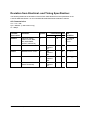
Microcontroller Components
Errata Sheet
May 29, 1998 / Release 1.0
Device:
SAK-C167CR-LM
SAK-C167CR-L25M
Stepping Code / Marking:
ES-CB, CB
Package:
MQFP-144
This Errata Sheet describes the deviations from the current user documentation. The
classification and numbering system is module oriented in a continual ascending sequence
over several derivatives, as well already solved deviations are included. So gaps inside this
enumeration could occur.
The current documentation is: Data Sheet: C167CR-4RM Data Sheet 07.97,
C167SR/CR-L25M Data Sheet Addendum 1998-03
User’s Manual: C167 Derivatives User’s Manual V2.0 03.96
Instruction Set Manual 12.97 Version 1.2
Note: Devices marked with EES- or ES are engineering samples which may not be
completely tested in all functional and electrical characteristics, therefore they should
be used for evaluation only.
The specific test conditions for EES and ES are documented in a separate Status Sheet.
Change summary to Errata Sheet Rel.1.0 for devices with stepping code/marking
ES-CB:
•
•
•
•
•
•
•
Modifications of ADM field while bit ADST = 0 (ADC.11)
P0H spikes after XPER write access and external 8-bit Non-multiplexed bus (X12)
Execution of PWRDN Instruction while pin NMI# = high (PWRDN.1)
Bidirectional Hardware Reset (RST.3)
Arithmetic Overflow by DIVLU instruction (CPU.17): workaround extended
ADC Overload Current (ADCC.2)
AC timing relaxations added
Semiconductor Group
Errata Sheet, C167CR-LM, ES-CB, CB, 1.1, Mh
- 1 of 10 -
Functional Problems:
PWRDN.1:
Execution of PWRDN Instruction while pin NMI# = high
When instruction PWRDN is executed while pin NMI# is at a high level, power down mode should not
be entered, and the PWRDN instruction should be ignored. However, under the conditions described
below, the PWRDN instruction may not be ignored, and no further instructions are fetched from
external memory, i.e. the CPU is in a quasi-idle state. This problem will only occur in the following
situations:
a) the instructions following the PWRDN instruction are located in external memory, and a multiplexed
bus configuration with memory tristate waitstate (bit MTTCx = 0) is used, or
b) the instruction preceeding the PWRDN instruction writes to external memory or an XPeripheral
(XRAM, CAN), and the instructions following the PWRDN instruction are located in external
memory. In this case, the problem will occur for any bus configuration.
Note: the on-chip peripherals are still working correctly, in particular the Watchdog Timer will reset the
device upon an overflow. Interrupts and PEC transfers, however, can not be processed. In case NMI#
is asserted low while the device is in this quasi-idle state, power down mode is entered.
Workaround:
Ensure that no instruction which writes to external memory or an XPeripheral preceeds the PWRDN
instruction, otherwise insert e.g. a NOP instruction in front of PWRDN. When a muliplexed bus with
memory tristate waitstate is used, the PWRDN instruction should be executed out of internal RAM or
XRAM.
Semiconductor Group
Errata Sheet, C167CR-LM, ES-CB, CB, 1.1, Mh
- 2 of 10 -
CPU.17:
Arithmetic Overflow by DIVLU instruction
For specific combinations of the values of the dividend (MDH,MDL) and divisor (Rn), the Overflow (V)
flag in the PSW may not be set for unsigned divide operations, although an overflow occured.
E.g.:
MDH
F0F0
MDL
Rn
MDH MDL
0F0Fh : F0F0h = FFFF FFFFh, but no Overflow indicated !
(result with 32-bit precision: 1 0000h)
The same malfunction appears for the following combinations:
n0n0 0n0n : n0n0
n00n 0nn0 : n00n
n000 000n : n000
n0nn 0nnn : n0nn
where n means any Hex Digit between 8 ... F
i.e. all operand combinations where at least the most significat bit of the dividend (MDH) and the divisor
(Rn) is set.
In the cases where an overflow occurred after DIVLU, but the V flag is not set, the result in MDL is
equal to FFFFh.
Workaround:
Skip execution of DIVLU in case an overflow would occur, and explicitly set V = 1.
E.g.:
CMP Rn, MDH
JMPR cc_ugt, NoOverflow
; no overflow if Rn > MDH
BSET V
; set V = 1 if overflow would occur
JMPR cc_uc, NoDivide ; and skip DIVLU
NoOverflow:
DIVLU Rn
NoDivide:
...
; next instruction, may evaluate correct V flag
Note:
- the KEIL C compiler, run time libraries and operating system RTX166 do not generate or use
instruction sequences where the V flag in the PSW is tested after a DIVLU instruction.
- with the TASKING C166 compiler, for the following intrinsic functions code is generated which uses
the overflow flag for minimizing or maximizing the function result after a division with a DIVLU:
_div_u32u16_u16()
_div_s32u16_s16()
_div_s32u16_s32()
Consequently, an incorrect overflow flag (when clear instead of set) might affect the result of one of the
above intrinsic functions but only in a situation where no correct result could be calculated anyway.
These intrinsics first appeared in version 5.1r1 of the toolchain.
Libraries: not affected
Semiconductor Group
Errata Sheet, C167CR-LM, ES-CB, CB, 1.1, Mh
- 3 of 10 -
ADC.11:
Modifications of ADM field while bit ADST = 0
The A/D converter may unintentionally start one auto scan single conversion sequence when the
following sequence of conditions is true:
(1) the A/D converter has finished a fixed channel single or continuous conversion of an analog
channel n > 0 (i.e. contents of ADCON.ADCH = n during this conversion)
(2) the A/D converter is idle (i.e. ADBSY = 0)
(3) then the conversion mode in the ADC Mode Selection field ADM is changed to Auto Scan Single
(ADM = 10b) or Continuous (ADM = 11b) mode without setting bit ADST = 1 with the same
instruction
Under these conditions, the A/D converter will unintentionally start one auto scan single conversion
sequence, beginning with channel n-1, down to channel number 0.
In case the channel number ADCH has been changed before or with the same instruction which
selected the auto scan mode, this channel number has no effect on the unintended auto scan
sequence (i.e. it is not used in this auto scan sequence).
Note:
When a conversion is already in progress, and then the configuration in register ADCON is changed,
- the new conversion mode in ADM is evaluated after the current conversion
- the new channel number in ADCH and new status of bit ADST are evaluated after the current
conversion when a conversion in fixed channel conversion mode is in progress, and after the
current conversion sequence (i.e. after conversion of channel 0) when a conversion in an auto scan
mode is in progress.
In this case, it is a specified operational behaviour that channels n-1 .. 0 are converted when ADM is
changed to an auto scan mode while a fixed channel conversion of channel n is in progress (see e.g.
C167 User’s Manual, V2.0, p16-4)
Workaround:
When an auto scan conversion is to be performed, always start the A/D converter with the same
instruction which sets the configuration in register ADCON.
RST.3:
Bidirectional Hardware Reset
When the bidirectional reset feature is enabled (bit BDRSTEN/SYSCON.3 = 1), and a short hardware
reset pulse (> 4 TCL) is applied to pin RSTIN#, the following problem may occur:
Pin RSTIN# may not be driven low by the internal circuitry for the duration of the internal reset
sequence if the falling edge of the hardware reset pulse occurred during the second cycle of a 2-cycle
instruction (e.g. CALL, RETI, TRAP). As a consequence, the level at pin RSTIN# may be pulled up to a
high level through the internal pullup in case the external reset source is no longer driving the pin low.
Note:
The internal reset sequence is always completed correctly. Software and Watchdog Timer reset are not
affected by this problem.
This problem will be fixed in the next step
X9:
Read Access to XPERs in Visible Mode
The data of a read access to an XBUS-Peripheral (XRAM, CAN) in Visible Mode is not driven to the
external bus. PORT0 is tristated during such read accesses.
Semiconductor Group
Errata Sheet, C167CR-LM, ES-CB, CB, 1.1, Mh
- 4 of 10 -
X12:
P0H spikes after XPER write access and external 8-bit Non-multiplexed bus
When an external 8-bit non-multiplexed bus mode is selected and P0H is used for general purpose I/O,
and an internal (byte or word) write access to an XBUS peripheral (e.g. XRAM, CAN, or I²C module) is
performed, and an external bus cycle is directly following the internal XBUS write cycle, then P0H is
actively driven with the write data for approx. 7ns (spikes on P0H).
The spikes also occur if P0H is configured as input. However, read operations from P0H are not
affected and will always return the correct logical state.
The spikes have the following position and shape in a typical application:
spikes occur after the rising edge of CLKOUT which follows the rising edge of ALE for the external bus
cycle
P0H.x = low
--> output low voltage rises to approx. 2.5V, spike width approx. 7ns (@ 0.2 Vcc)
P0H.x = high --> output high voltage drops to approx. 2.0V, spike width approx. 7ns (@ 0.8 Vcc)
Referring to a worst case simulation the maximum width of the spikes may be 15ns with full amplitude
(Vcc/Vss). But this might not be seen on application level.
Note that if any of the other bus modes is selected in addition to the 8-bit non-multiplexed mode, P0H
can not be used for I/O per default.
Workaround:
-
use a different port instead of P0H for I/O when (only) an external 8-bit non-multiplexed bus mode
is selected
or use a different bus type (e.g. 8-bit multiplexed, where P1H may be used for I/O instead of P0H)
or the spikes on P0H may be filtered with an application specific RC element,
or do not perform an external bus access directly after an XBUS write access:
this may be achieved by an instruction sequence which is executed in internal ROM/Flash/OTP,
or internal RAM, or internal XRAM
e.g.
ATOMIC #3
; to prevent PEC transfers which may access external memory
instruction which writes to XBUS peripheral
NOP
NOP
Semiconductor Group
Errata Sheet, C167CR-LM, ES-CB, CB, 1.1, Mh
- 5 of 10 -
Deviation from Electrical- and Timing Specification:
The following table lists the deviations of the DC/AC characteristics from the specification in the
C167CR-4RM Data Sheet 7.97 and C167SR/CR-L25M Data Sheet Addendum 1998-03
AC Characteristics:
Vcc = 5 V ± 5 %
fcpu = 24 MHz (L25M version only)
CL = 50 pF
Problem
Parameter
Symbol
Limit Values Unit Test
min.
short name
max.
Condition
DCVOL.1
Output low voltage
(Port0/1/4, ALE, RD#,
WR#, WRH#/BHE,
CLKOUT, RSTOUT#)
VOL
-
0.45
V
IOL = 2.0 mA
instead of
2.4 mA
DCAH.1
ALE active current
IALEH
1000
instead of
500
-
µA
VOUT = 2.4 V
DCRL.1
RD#/WR# active current
IRWL
-600
instead of
-500
-
µA
VOUT = VOLmax
DCP6L.1
Port 6 active current
IP6L
-600
instead of
-500
-
µA
VOUT = VOLmax
DCHYS.1
Input Hysteresis
(Special Threshold)
HYS
300
instead of
400
-
mV
-
Semiconductor Group
Errata Sheet, C167CR-LM, ES-CB, CB, 1.1, Mh
- 6 of 10 -
Parameter
Symbol
CPU Clock
= 20 MHz
Variable CPU Clock Unit
1/2TCL = 1 to 24 MHz
min.
max.
min.
max.
10+ta
instead of
15+ta
-
TCL-15+ta
instead of
TCL-10+ta
-
ns
WR#/WRH# low time t12
(with RW-delay)
38+tc
instead of
40+tc
-
2TCL-12+tc
instead of
2TCL -10+tc
-
ns
WR#/WRH# low time t13
(no RW-delay)
63+tc
instead of
65+tc
-
3TCL-12+tc
instead of
3TCL -10+tc
-
ns
Address hold after
WRH#
t28
-5+tf
instead of
0+tf
-
-5+tf instead of 0+tf
ns
ALE falling edge to
CS#
t38
-7-ta
10-ta
instead of 4-ta
-7-ta
instead of
4-ta
10-ta
ns
RDCS#/WRCS# low t48
time
(with RW-delay)
38+tc
instead of
40+tc
-
2TCL-12+tc
instead of
2TCL -10+tc
-
ns
RDCS#/WRCS# low t49
time
(with RW-delay)
63+tc
instead of
65+tc
-
3TCL-12+tc
instead of
3TCL -10+tc
-
ns
ALE high time
t5
-
Notes:
1) Pin READY# has an internal pullup (all C167xx derivatives). This will be documented in the next
revision of the Data Sheet.
2) Timing t28: Parameter description and test changed from ’Address hold after RD#/WR#’ to ’Address
hold after WR#’. It is guaranteed by design that read data are internally latched by the controller before
the address changes.
3) During reset, the internal pullups on P6.[4:0] are active, independent whether the respective pins
are used for CS# function after reset or not.
Semiconductor Group
Errata Sheet, C167CR-LM, ES-CB, CB, 1.1, Mh
- 7 of 10 -
ADCC.2:
ADC Overload Current
During exceptional conditions in the application system an overload current IOV can occur on the analog
inputs of the A/D converter when VAIN > Vdd or VAIN < Vss. For this case, the following conditions are
specified in the Data Sheet:
IOVmax = | ±5 mA |
The specified total unadjusted error TUEmax = | ±2 LSB | is only guaranteed if overload conditions occur
on maximum 2 not selected analog input pins and the absolute sum of input overload currents on all
analog input pins does not exceed 10 mA.
Due to an internal problem, the specified TUE value is only met for a positive overload current IOV ≤ +5
mA (all currents flowing into the microcontroller are defined as positive and all currents flowing out of it
are defined as negative).
If the exceptional conditions in the application system cause a negative overload current, then the
maximum TUE can be significantly exceeded (depending on value of IOV and RAIN of converted
channel):
when the negative overload current occurs on analog input channel ANn (n≠10), the accuracy of the
neighbour channels ANn-1 and ANn+1 is affected
when the negative overload current occurs on channel AN10, the accuracy of all other analog input
channels is affected.
Semiconductor Group
Errata Sheet, C167CR-LM, ES-CB, CB, 1.1, Mh
- 8 of 10 -
History List (since device step BA)
Functional Problems
Functional
Problem
Short Description
Fixed in
step
PWRDN.1
Execution of PWRDN Instruction while pin NMI# = high
CPU.8
Jump instruction in EXTEND sequence
CB
CPU.9
PEC Transfers during instruction execution from Internal RAM
CB
CPU.11
Stack Underflow during Restart of Interrupted Multiply
CB
CPU.17
Arithmetic Overflow by DIVLU instruction
RST.1
System Configuration via P0L.0 during Software/Watchdog Timer Reset
RST.3
Bidirectional Hardware Reset
ADC.8
CC31/ADC Interference
CB
ADC.10
Start of Standard Conversion at End of Injected Conversion
CB
ADC.11
Modifications of ADM field while bit ADST = 0
X9
Read Access to XPERs in Visible Mode
X12
P0H spikes after XPER write access and external 8-bit Non-multiplexed bus
CB
AC/DC Deviations
AC/DC
Deviation
Short Description
Fixed in
step
see pages 6 .. 8
Semiconductor Group
Errata Sheet, C167CR-LM, ES-CB, CB, 1.1, Mh
- 9 of 10 -
In addition to the description in the C167 Derivatives User’s Manual V2.0, the following feature
enhancements have been implemented in the C167CR-LM CB-step and all higher steps:
Incremental position sensor interface
For each of the GPT1 timers T2, T3, T4 of the GPT1 unit, an additional operating mode has been
implemented which allows to interface to incremental position sensors (A, B, Top0). This mode is
selected for a timer Tx via TxM = 110b in register TxCON, x = (2, 3, 4). Optionally, the contents of T5
may be captured into register CAPREL upon an event on T3. This feature is selected via bit CT3 = 1 in
register T5CON.10
Compatibility with previous versions:
In previous versions (e.g. C167CR-LM BA-step), both of the settings (TxM = 110b, T5CON.10 = 1)
were reserved and should not be used. Therefore, systems designed for previous versions will also
work without problems with the C167CR-LM CB-step and all higher steps.
Oscillator Watchdog
The C167CR-LM CB-step and all higher steps provide an Oscillator Watchdog (OWD) which monitors
the clock at XTAL1 in direct drive mode. In case of clock failure, the PLL Unlock/OWD Interrupt
Request Flag (XP3IR) is set and the internal CPU clock is supplied with the PLL basic frequency. This
feature can be disabled by a low level on pin Vpp/OWE. See also C167CR-4RM Data Sheet 7.97.
Bidirectional Reset
The C167CR-LM CB-step and all higher steps allow to indicate an internal watchdog timer or software
reset on the RSTIN# pin which will be driven low for the duration of the internal reset sequence. This
option is selectable by software via bit BDRSTEN/SYSCON.3. After reset, the bidirectional reset option
is disabled (BDRSTEN/SYSCON.3 = 0). See also C167CR-4RM Data Sheet 7.97. Beginning with the
CB-step of the C167CR-LM, RSTIN# will also be driven low for the duration of the internal reset
sequence when this reset was initiated by an external HW reset signal on pin RSTIN#.
Please note also the following functional difference to the C167CR-LM BA-step:
XBUS Peripheral Enable Bit XPEN/SYSCON.2
In the C167CR-LM CB-step and all higher steps, bit SYSCON.2 is a general XBUS Peripheral Enable
bit, i.e. it controls both the XRAM and the CAN module.
Compatibility with previous versions:
When bit SYSCON.2 = 0 (default after reset) in the C167CR-LM CB-step, and an access to an address
in the range EF00h ... EFFFh is made, either an external bus access is performed (if an external bus is
enabled), or the Illegal Bus Trap is entered. In previous versions (e.g. C167CR-LM BA-step), the CAN
module was accessed in this case.
Systems where bit SYSCON.2 was set to ’1’ before an access to the CAN module in the address range
EF00h ... EFFFh was made will also work without problems with the C167CR-LM CB-step and all
higher steps.
Application Support Group, Munich
Semiconductor Group
Errata Sheet, C167CR-LM, ES-CB, CB, 1.1, Mh
- 10 of 10 -