1
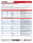
Merih DDCA60 Operation and User Manual I Merih Asansör A.Ş. Merih DDCA60 Operation and User Manual I Merih Asansör A.Ş. 1. WARNINGS ! CAUTION This manual contains user guidelines for Merih DDCA60 hardware version v1.05 and software version v1.03. This document will be updated with differences result from version differences. Merih Asansor A.S is not responsible for typos or errors that result from version differences. It is mandatory that Merih DDCA60 is used by technical personnel who are capable of reading, understanding and applying the rules written in this document. Merih Asansor A.S supports the design of safe products, however it accepts no liability for damages caused by user misuse. BEFORE FIRST USE Please read this instruction manual before using Merih DDCA60 (and/or its additional hardwares) for the first time. For safety it is essential to understand the rules regarding the installation and operation of this product. GENERAL NOTE The technical personnel who will use Merih DDCA60 should be familiar with the full functionality of the equipment in addition to the assembly and wiring of it. In order to avoid electrical shocks or any other damage to the product; please check that - the equipment is not plugged in before assembly and first use - all wiring is correct and stable - corresponding hardware and software is used according to the actuating mechanism of the door - all operation is carried out in accordance with ESD rules. With this purpose the personnel should discharge themselves electrostatically. The personnel should not touch to connectors or other circuit components with bare hands. 12 1 Merih DDCA60 Operation and User Manual I Merih Asansör A.Ş. Merih DDCA60 Operation and User Manual I Merih Asansör A.Ş. 5 – ADDITIONAL MODULES I4: Fast Signal Input O3: Fully Closed Output O2:Fully Opened Output 2. DEVICE AND LIMITATIONS Merih DDCA60 is an electronic board for fully automatic doors. Supply Voltage 20-24V AC 28-34V DC Encoder One channel or double channel 20-1024 pulse per revolution Motor Type 24V Brushed DC Motor Motor Power Max 150W Door Length 35 – 250 cm Door driving speed 1cm/s – 40 cm/s Operation temperature -20˚C ~ 50˚C 5.1. Door Battery Module (DBU) Door Battery Unit (or DBU in short) ; charges the battery in a controlled way for having longer life batteries, as long as 24V power is available on DDCA60. When power outage occurs, provides DDCA60 to supply from battery. In this case, prevents passengers to stay in elevator cabin. DEVICE USAGE AND OPERATION SEQUENCE Complete the socket connections Limit Switch (Sensor) socket Input (Command) socket O1 (Blockage Relay) socket Power the card up Choose the desired language Update socket connection settings Do the Automatic Recognition Check the door profile Improve the door profile by parameters when necessary Normal Mode and Operate DBU, (if "On Floor Limit Switch" is active) opens the door fully and power downs the DDCA60 board on power outage state, in order to stop discharging battery. Green led on the board indicates that batteries are being charged and the red led indicates that the battery terminals are reversely connected. If there is no power on the board, although DBU is connected and batteries are full; this means that DBU is powered off itself in case of discharge. If you want to power DDCA60 up without power (via battery supply), you should press both of the buttons on the DBU board, on the same time. In this way, board is powered up once, and does not need to hold down buttons anymore. You may use the door or board for any operation. However if the door becomes fully open, and "On Floor Limit Switch" is active at the same time; DBU will power off the board again. Supplying the batteries directly is not supported on the Merih DDCA60 board. Door Battery Unit (DBU) and DBU cable must be used definitely. 5.2. Fire Module (FM) Fire Module (FM) must be plugged if the door will be used as a fire elevator extraordinarily. I4: Fast Signal Input: The signal which comes from the main control board and provides the door move fast (Fire Mode). O3: Fully Closed Output: The signal that informs the main control board that the door is fully closed. O2: Fully Opened Output: The signal that informs the main control board that the door is fully opened. If fire module is plugged and the necessary connections are done, I4 (Fast Signal) must be set as "Yes-Normally:1" or "Yes-Normally:0" in the Socket Settings menu. Additional setting is not required for O2 and O3 signals. These output relays work as Normally Open (N/O). 2 11 Merih DDCA60 Operation and User Manual I Merih Asansör A.Ş. Merih DDCA60 Operation and User Manual I Merih Asansör A.Ş. MOUNTING AND SOCKET CONNECTIONS OF THE BOARD Door Slowdowns Early Be sure that Door Recognition is done. Be sure that Skate Length is entered correctly. Reduce the Slow Distance in mentioned direction. Door Detects Blockage Unnecessary Be sure that Door Recognition is done. Be sure that Skate Length is entered correctly. Check the Photocell Settings in Socket Settings menu (Yes Normally 1, Yes Normally 0 or No N/A) Be sure that pressure settings are high enough Blockage Relay Output Motor Output Encoder Input +5V: Encoder + GND: Encoder – A: Encoder A B: Encoder B Sensor Input +24V: Limit switch common S1: Closed Limit Switch S2: Opened Limit Switch S3: Photocell S4: On Floor Limit Switch 20-24V AC Power Input Overheat on Motor or DDCA60 S3 S4 S1 S2 GND +5V ~ ~ +24V Reduce the “Hold Open Pressure“ or “Hold Close Pressure” A B Motor O1 89 mm Door Recognition Problems 24V DC Output +24V GND Door Length is Detected Incorrect Door length may be detected with +- 5 cm. This situation does not affect the door comfort, therefore it could be neglected. If the door detected the length of the door with an error more than 5 cm, try again by increasing the “Door Recognition Pressure” parameter. Choose the right selection of telescopic or central door type. Make sure that the skate works well and does not hang out (achieving both opening and closing movements exactly) in the closing direction. COM I1 I2 I3 Command Input Com: Common Signal I1: Close Signal Input I2: Open Signal Input I3: Slow Signal Input Gives “Limit Switch Error” message Error 1: Both limit switches are detected. Check Sensor Socket settings. Error 2, Error 3, Error 4: Open Limit Switch and Close Limit Switch are interchanged, or limit switches are selected as “Yes - Normally…” although they are not available. m 108 m 108 mm Door Battery Unit (DBU) Input Hits Very Fast on Door Recognition Reduce the “Door Recognition Velocity” parameter. 10 Fire Module Input Smart Card (Dongle) Input 3 m 89 m Gives “Encoder Error” Be sure that encoder and motor connections are correct. If the “Door Recognition Pressure” is entered too low, door may not move. Try to increase the parameter. Merih DDCA60 Operation and User Manual I Merih Asansör A.Ş. Merih DDCA60 Operation and User Manual I Merih Asansör A.Ş. 3. USER INTERFACE 4 - TROUBLESHOOTING Merih DDCA.60 board has a menu system including a LCD screen and buttons for setting necessary parameters and managing the board. Selection Login Main Menu Language Press cross key for 5 secs No selection in 15 secs. No selection in 10 secs. No Power on Board Up Key Cross Key: to enter an upper level menu Be sure that the green led below 24VAC (L2) is on. If red led (L1) is on instead of the green one, change the fuse of the board (250V 8A). Be sure that 24VAC Input Socket has power, if not, check transformer input and output connections. No Movement on the Door Left Key: for browsing on the same level menus Normal Mode Down Key: to enter a lower level menu Right Key: for browsing on the same level menus Be sure that Power Input and Motor Socket connections are correct and in contact. To test the correction of these terminal connections, “Manual Control” should be selected in the main menu and door movement should be observed. Increase the power enough which allows the door movement. If there is still no movement on the door, be sure that 24VAC is available on the Power Input Socket. If the door is moving in Manual Control, but there is no movement in Test Drive and/or Normal Mode: Try to increase pressure parameters (Door Recognition Pressure, Opening Pressure, Closing Pressure, etc.) Be sure that Input (Command) Socket Settings are correct. (One signal-Two Signal Setting) Main Menu TEST DRIVE SETTINGS DOOR RECOGNITION MANUAL CONTROL Door Moves Too Fast COUNTERS Fast Signal (Settings-->Socket Settings->I4) may be activated. This mode is for fire elevators. If is not used as a fire elevator, should be set as “No- N/A ”. Size/Length Settings Velocity Settings Pressure/Power Settings Socket Settings Open/Close Count Be sure that Door Recognition is done. Be sure that encoder connection is correct. Door Length Opening Max Velocity Opening Pressure S1:Lim. Switch Closed Powercut Count Skate Length Closing Max Velocity Closing Pressure S2:Lim. Switch Open Working Time Opening Slow Velocity Skate Opening Pressure S3: Photocell Low Power Fault Closing Slow Velocity Skate Closing Pressure S4:Lim. Switch On Floor Opening Deceleration Opening Skate Velocity Hold Open Pressure I1:Close Door Closing Deceleration Closing Skate Velocity Hold Close Pressure Door Recognition Velocity Nudging Opening Pressure Opening Acceleration Closing Acceleration Opening Slow Distance Closing Slow Distance Door Always Waits Either Fully Opened or Fully Closed Position If this situation occurs in Normal Mode, make sure that Input (Command) socket settings are correct and check the signal that you desire (Open/Close) is available by monitoring the related leds. Door Moves in Reverse Direction If the door moves in a different direction rather than the specified direction displayed on the LCD screen, change sides of the motor terminal connections and repeat the “Door Recognition” process. I2:Open Door I3:Slow Signal Door Hits Before Slowing Down Enough I4:Fast Signal Be sure that Door Recognition is done. Be sure that Skate Length is entered correctly. Enter an enough deceleration ramp value. Reduce the Slow Velocity in mentioned direction. Nudging Closing Pressure Door Recognition Pressure 4 Return back to Factory Settings 9 Merih DDCA60 Operation and User Manual I Merih Asansör A.Ş. Merih DDCA60 Operation and User Manual I Merih Asansör A.Ş. 3.5.3 Pressure/Power Settings Contains parameters which determine the maximum power to be applied during the door movement in case of door strain (see page 4). 3.1 Automatic Door Recognition Door recognition mode, provides Merih DDCA60 board to realize the type of the door and door length, by moving the door first closing and then opening direction. Pressure parameters in opening or closing direction directly affect the sensitivity response of the door in any blockage condition. Therefore, not only performance but also the safety of the door must be considered when setting these parameters. Normal Mode Nudging Mode: If blockage condition is detected while moving the door, changes the direction and tries to complete the movement in reverse direction. Then attempts to move in blockage direction again. If detects blockage in that direction again, and this is repeated 3 times in a row, detects a situation that prevents to complete the movement and enters nudging mode. In this mode, door moves in blockage detected direction by high pressure (nudging pressure) and slow speed with an audible warning alert. Nudging Mode is also activated by the “Slow Command” signal. The aim of the nudging mode is, to remove the problem which causes to prevent door movement. 3.5.4 Socket Settings Includes the parameters which determine operation type of the Sensor (Limit switch) and Input (Command) sockets. (see page 4 for these parameters). After language selection, find the “Door Door Recognition” in main menu Recognition via direction keys Press and hold down the “Up” key until you return to the “Normal Mode” Press “Down” key for “Door Recognition” and follow instructions on LCD screen Press “Cross” key to leave the “Door Recognition” On “Black” type doors, door length is shown on the screen. Door length may be detected 5 cm more or less, this situation does not cause any negative effect on door comfort. 3.2 Test Drive Test Drive is being used to observe how the door is moving with the updated parameters. During Test Drive mode, board opens and closes the door constantly. For these parameters, there are three values available corresponding to the operation type: Yes-Normally:1 : This option must be selected if no power in mentioned socket input (led off) when signal is inactive, although there is power on the socket (led on) when the signal is active. Yes-Normally:0 : This option must be selected if there is power in the socket input (led on) when signal is inactive, although there is no power on the socket (led off) when the mentioned signal is active. No- N / A: Specifies that the signal is not used. Normal Mode Main Menu & Language Selection Press “Cross” key for 5 secs. After language selection, find the “Test Drive” in main menu via direction keys Press and hold down the “Up” key until you return to the “Normal Mode” In Black Series doors, limit switches are not used, so “No- N / A” should be selected for operation type of S1 and S2 sockets ! Main Menu & Language Selection Press “Cross” key for 5 secs. If the main control board has one signal, instead of two signals as “Close the Door” and “Open the Door; ‘I2 – Open Door’ parameter must be selected as “No- N / A”. In this case, door will be closing while ‘I1 – Close Door’ signal exists and will be opening when signal is gone. If possible; configuring the main control board for two signals is more secure rather than one signal. Test Drive Press the “Down” key in order to start Test Drive Press “Cross” direction key to leave the “Test Drive” 3.3 Manual Control In this menu, the door can be moved in opening or closing direction regardless of door parameters. In this case, a constant voltage is applied to the terminals of the motor in the desired direction. Unused signals in “Socket Settings”, must be definitely selected as “No- N / A”. Normal Mode Press “Cross” key for 5 secs. Main Menu & Language Selection After language selection, find the “Manual Control” in main menu via direction keys 3.6. Return Back to Factory Settings Press and hold down the “Up” key until you return to the “Normal Mode” Parameters are already set to defaults as factory setting. But if the user desires, can configure as he/she want. But if undesired movements occur on the door due to parameter changes, this feature is being used in order to return back to the factory defaults. To return back to the factory defaults, simply follow the instructions on LCD screen. Manual Control Hold down “Left” or “Right” key for moving the door in opening or closing direction Press “Cross” direction key to leave the “Manual Control” Press the “Down” key in order to enter Manual Control Set the motor movement power by “Up” and “Down” keys. As long as the key associated with direction is pressed, door tries to move in that direction. As comfort control is inactive, the user must be careful that the door doesn’t hit too fast. 8 5 Merih DDCA60 Operation and User Manual I Merih Asansör A.Ş. Merih DDCA60 Operation and User Manual I Merih Asansör A.Ş. 3.4 Counters Counters menu contains information about board operation and statistics. Normal Mode Press “Cross” key for 5 secs. Main Menu & Language Selection Press and hold down the “Up” key until you return to the “Normal Mode” After language selection, find the “Counters” in main menu via direction keys Counters Press “Cross” direction key to leave the “Counters” Press the “Down” key in order to enter Counters menu 3.5.1 Size/Length Settings Contains size and length parameters shown in the door movement profile graphs below, in opening or closing direction (see page 4). “Skate Length” parameter is in “mm” unit, although all the other parameters are in “cm” unit. 3.5.2 Velocity Settings Contains velocity parameters shown in the door movement profile graphs below, in opening or closing direction (see page 4). Use “Left” and “Right” direction keys to see other counters Open/Close Count: Shows how many times door is opened and closed. Powercut Count: Shows the power outage count while board is working. Working Time: Indicates the operation time of the board in “days” unit. Low Power Fault: Shows the number of times when there is a voltage drop in transformer because of the door strain. 3.5 Settings Parameters in the “Settings Menu” are grouped by sub-menus as Size/Length, Velocity, Pressure/Power and Socket Settings. (see page 4.) Normal Mode Press “Cross” key for 5 secs. Main Menu & Language Selection Press and hold down the “Up” key until you return to the “Normal Mode” After language selection, find the “Settings” in main menu via direction keys Press the “Down” key in order to enter Settings menu Door movement profile in opening direction Press “Cross” direction key to leave the “Settings” Use “Left” and “Right” direction keys to access other parameters in the sub‐menu that you are in Use “Up” and “Down” keys to change the value of the parameter shown on the LCD screen. 6 Counters Use “Left” and “Right” direction keys for surfing in the Settings menu Press the “Down” key to enter a sub‐menu and access parameters. Door movement profile in closing direction Use “Cross” direction key to return one level up 7