1
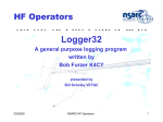
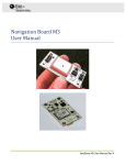
ADXL345
Data Sheet
I2C
Due to communication speed limitations, the maximum output
data rate when using 400 kHz I2C is 800 Hz and scales linearly
with a change in the I2C communication speed. For example,
using I2C at 100 kHz would limit the maximum ODR to 200 Hz.
Operation at an output data rate above the recommended maximum may result in undesirable effect on the acceleration data,
including missing samples or additional noise.
With CS tied high to VDD I/O, the ADXL345 is in I2C mode,
requiring a simple 2-wire connection, as shown in Figure 40.
The ADXL345 conforms to the UM10204 I2C-Bus Specification
and User Manual, Rev. 03—19 June 2007, available from NXP
Semiconductor. It supports standard (100 kHz) and fast (400 kHz)
data transfer modes if the bus parameters given in Table 11
and Table 12 are met. Single- or multiple-byte reads/writes are
supported, as shown in Figure 41. With the ALT ADDRESS pin
high, the 7-bit I2C address for the device is 0x1D, followed by
the R/W bit. This translates to 0x3A for a write and 0x3B for a
read. An alternate I2C address of 0x53 (followed by the R/W bit)
can be chosen by grounding the ALT ADDRESS pin (Pin 12).
This translates to 0xA6 for a write and 0xA7 for a read.
VDD I/O
ADXL345
RP
RP
PROCESSOR
CS
D IN/OUT
SDA
ALT ADDRESS
There are no internal pull-up or pull-down resistors for any
unused pins; therefore, there is no known state or default state
for the CS or ALT ADDRESS pin if left floating or unconnected.
It is required that the CS pin be connected to VDD I/O and that
the ALT ADDRESS pin be connected to either VDD I/O or GND
when using I2C.
07925-008
D OUT
SCL
Figure 40. I2C Connection Diagram (Address 0x53)
If other devices are connected to the same I2C bus, the nominal
operating voltage level of these other devices cannot exceed VDD I/O
by more than 0.3 V. External pull-up resistors, RP, are necessary for
proper I2C operation. Refer to the UM10204 I2C-Bus Specification
and User Manual, Rev. 03—19 June 2007, when selecting pull-up
resistor values to ensure proper operation.
Table 11. I2C Digital Input/Output
Parameter
Digital Input
Low Level Input Voltage (VIL)
High Level Input Voltage (VIH)
Low Level Input Current (IIL)
High Level Input Current (IIH)
Digital Output
Low Level Output Voltage (VOL)
Test Conditions
Unit
0.3 × VDD I/O
V
V
µA
µA
0.7 × VDD I/O
VIN = VDD I/O
VIN = 0 V
0.1
−0.1
VDD I/O < 2 V, IOL = 3 mA
VDD I/O ≥ 2 V, IOL = 3 mA
VOL = VOL, max
fIN = 1 MHz, VIN = 2.5 V
Low Level Output Current (IOL)
Pin Capacitance
0.2 × VDD I/O
400
V
mV
mA
pF
3
8
Limits based on characterization results; not production tested.
SINGLE-BYTE WRITE
MASTER START
SLAVE ADDRESS + WRITE
DATA
REGISTER ADDRESS
ACK
SLAVE
ACK
STOP
ACK
MULTIPLE-BYTE WRITE
MASTER START
SLAVE ADDRESS + WRITE
SLAVE
STOP
DATA
DATA
REGISTER ADDRESS
ACK
ACK
ACK
ACK
SINGLE-BYTE READ
MASTER START
SLAVE ADDRESS + WRITE
SLAVE
START1
REGISTER ADDRESS
ACK
SLAVE ADDRESS + READ
ACK
NACK
ACK
DATA
ACK
DATA
STOP
MULTIPLE-BYTE READ
MASTER START
SLAVE
SLAVE ADDRESS + WRITE
START1
REGISTER ADDRESS
ACK
ACK
SLAVE ADDRESS + READ
ACK
NOTES
1. THIS START IS EITHER A RESTART OR A STOP FOLLOWED BY A START.
2. THE SHADED AREAS REPRESENT WHEN THE DEVICE IS LISTENING.
Figure 41. I2C Device Addressing
Rev. D | Page 18 of 40
NACK
STOP
DATA
07925-033
1
Limit 1
Max
Min