1
Background:
The first two words that come to mind when one thinks of electronics are voltage and
current. Every electrical phenomenon can be described in some form based on these two
fundamental properties. Despite this, much of electrical engineering devolves away from these
fundamentals and understanding is obscured by adding layers upon the foundation of voltage and
current. The question that needs to be asked of any electronic component is how the voltage is
related to the current. This understanding brings powerful insight into the design of electronic
circuits.
The simplest electronic component is the resistor. The resistor has a simple relationship
between voltage and current. The current flowing through a resistor is the voltage across the
resistor divided by the resistance of the resistor. The equations below show all the relationships
between voltage, current and resistance.
𝑅=
𝑉
𝑉
→𝑉 =𝐼∗𝑅 →𝐼 =
𝐼
𝑅
The value of a resistor can be determined by applying a known voltage across it and measuring
the current flowing through it. If this was to be plotted on the X-Y plane, it follows that voltage
should be on the X axis since it is the independent variable and current should be plotted on the
Y axis since it is the dependent variable. This could be reversed but generally due to the ease of
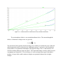
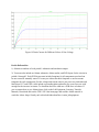
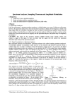
creating variable voltage sources this was the convention adopted. The plot in fig. 1 created
using LTSpice shows three resistor values and their current-voltage or I-V characteristics. It is
tempting to think of resistance as slope but in this plot the slope is really the reciprocal of
resistance, or conductance. Thus for the 0.5 ohm resistor at 10V the current is equal to
1
1
𝐼 = 𝑉 ∗ 𝑅 = 10 ∗ 0.5 = 20 𝐴. It is important to always be aware of the orientation of the axes.
Sometimes I-V plots are flipped in order to make certain data more clear. For this lab the plots
will always be shown with voltage on the X axis and current on the Y axis.