1
OPC Factory Server
User's Manual
Contents
OPC Factory Server
Section
Page
___________________________________________________________________________
1
ENGLISH
OPC Factory Server
ENGLISH
OPC Factory Server
Section
Contents
Page
___________________________________________________________________________
2
Section
Contents
Page
1 Presentation
1/1
1.1
Introduction
1/1
1.2
PLC Compatibility
1/2
1.3
Communication Media Supported
1/2
2 Installation
2/1
2.1
Contents of the Product
2/1
2.2
Hardware and Software Configuration
2/2
2.3
Installation Procedure
2/4
2.4
Defining the Parameters for Local or Remote Operation
2/7
3 Configuration Tool
3/1
3.1
Description
3/1
3.2
Server Tab
3/3
3.3
Symbols Tab
3/5
3.4
Alias Tab
3/7
3.5
Analog Tab
3/9
3.6
MB serial Tab
3/10
___________________________________________________________________________
3
ENGLISH
OPC Factory Server
ENGLISH
OPC Factory Server
Contents
Section
Page
3.7
Simulator Tab
3/10
3.8
Misc. Tab
3/11
3.9
Advanced Tab
3/12
3.10 GUI : Menus, Tool Bar and Status Bar
3/12
3.11 Saving/Restoring Configuration
3/13
3.12 OFSconf Options
3/14
4 Functions of the Product
4/1
4.1
Definition of a Group of Items
4/1
4.2
Synchronous Services : Read / Write
4/1
4.3
Asynchronous Services
4/2
4.4
Periodic Read Service
4/3
4.5
Mechanism for Adjusting the Communication Time-Out with a
Device
4/4
4.6
Mechanism for Managing the PLC Operating Mode
4/4
4.7
Mechanism for Accessing the OFS Server
4/5
4.8
Symbolic Support
4/6
4.9
Browse Support
4/6
___________________________________________________________________________
4
Section
Contents
Page
4.10 Concept Link
4/6
4.11 Simulator
4/7
5 Type of variables handles by the server
5/1
5.1
PL7 Variables
5.1-1 Standard Objects
5.1-2 Grafcet Objects
5.1-3 Standard Function Blocks
5.1-4 Table Objects
5/3
5/3
5/4
5/5
5/6
5.2
Concept Variables
5/8
5.3
ModSoft variables
5/9
5.4
Local Variables
6 Using the Server
5/10
6/1
6.1
Introduction
6/1
6.2
The Operating Phases of the OFS Server
6/2
6.3
Groups of Items
6/3
6.4
Managing Tables
6/4
6.5
Consistency of the Read Operation
6/5
6.6
Consistency of the Write Operation
6/6
6.7
Asynchronous Operation
6/7
___________________________________________________________________________
5
ENGLISH
OPC Factory Server
ENGLISH
OPC Factory Server
Section
Contents
Page
6.8
Using Periodic Reading
6.9
Using
6.9.1
6.9.2
6.9.3
Dead-Banding
Definition
Description of the Dead-Banding Mechanism
Using Dead-Banding in a Client Application
6/8
6/9
6/9
6/9
6/10
6.10 Adjusting the Time-Out
6/12
6.11 Managing the PLC Operating Mode
6/12
6.12 Communication
6/13
6.13 Managing the Symbols
6.13-1 PL7 exported symbol table file
6.13-2 PL7 exported application file
6.13-3 Concept exported symbol table file
6.13-4 Modsoft exported symbol file
6.13-5 CSV symbol table file
6/17
6/18
6/18
6/19
6/19
6/20
6.14 Browse support
6/21
6.15 Managing Standard PL7 Function Blocks
6/23
6.16 Concept Link Support
6/23
6.17 Error Handling
6.17-1 Error Feedback Mechanism
6.17-2 Objects Outside the Software Configuration
6/24
6/24
6/27
6.18 Specific Items
6/28
___________________________________________________________________________
6
Section
Contents
Page
7 User's Guide
7.1
OPC custom
7.2
Description of the OLE Automation Interface Exposed
7.2-1 Error Codes
7.2-2 CreateObject : Creating the OFS Server in Visual Basic
7.2-3 AddGroup : Creating a Group of Items
7.2-4 RemoveGroup : Removing a Group of Items
7.2-5 AddItems : Adding Items to a Group
7.2-6 OPCRead : Reading the Items in a Group
7.2-7 ActiveStatus : Activation/Deactivation of the Periodic
Reading of a Group
7.2-8 OnDataChange : Periodic Reception of Notifications
7.2-9 AddCallbackReference : Subscribing to the Notification
Service
7.2-10 DropCallbackReference : Unsubscribing to the Notification
Service
7.2-11 PercentDeadBand : Managing the Dead-Banding of a
Group
7.2-12 OPCWrite : Writing Items in a Group
7.2-13 GetErrorString : Obtaining an Error Message
7.2-14 MajorVersion : Information on the OFS Server
8 Performance
8.1
Target Performance
7/1
7/1
7/2
7/4
7/4
7/5
7/8
7/9
7/12
7/15
7/16
7/18
7/19
7/20
7/21
7/23
7/25
8/1
8/1
___________________________________________________________________________
7
ENGLISH
OPC Factory Server
ENGLISH
OPC Factory Server
Contents
Section
Page
9 Appendix
9.1
9/1
Tutorial on Creating a Client Application in Visual Basic
9.1-1 CreateObject : Creating an OPC Server Object
9.1-2 AddGroup : Adding a Group
9.1-3 AddItems : Adding Items in a Group
9.1-4 OPCRead : Synchronous Reading of a Group
9.1-5 Periodic Reading of the User Group
9.1-6 OPCWrite : Writing the Value of the Items in a Group
9.1-7 DropCallbackReference and RemoveGroup : Closing the
Tutorial
9.1-8 GetErrorString : Managing OPC, OFS and Win32 Errors
9.1-9 MajorVersion : Information on the OFS Server
9/12
9/13
9/14
9.2
Tutorial on Creating a Client Application in C ++
9.2-1 Creating an OPC Server Object
9.2-2 Adding a Group
9.2-3 Adding Items to a Group
9.2-4 Synchronous Reading of a Group
9.2-5 Periodic Reading of the User Group
9.2-6 Writing the Value of the Items to a Group
9.2-7 Closing the Tutorial
9.2-8 Managing OPC, OFS and Win32 Errors
9/15
9/16
9/16
9/17
9/17
9/17
9/17
9/18
9/18
9.3
OFS server compatibility
9/19
9.4
Glossary
9/20
9.5
Abbreviations
9/21
9.6
Recommendations in the Event of a Problem
9/22
9.7
9/1
9/4
9/5
9/6
9/7
9/8
9/11
Exhaustive List of Error Codes
9/23
9.7-1 Main errors defined by OLE
9/23
9.7-2 Errors Defined by the OPC Standard
9/24
9.7-3 Errors Defined by the OFS Server
9/25
___________________________________________________________________________
8
Section 11
Presentation
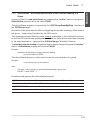
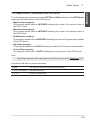
1 Presentation
Introduction
OFS (OPC Factory Server) is a multi-PLC data server able to communicate with realtime I/O devices in the TSX Compact, TSX Micro, TSX Momentum, TSX/PCX/PMX
Premium and TSX Quantum families, and serve data to OPC clients.
This means that it provides a group of services (primitives) to client applications for
access to control system variables.
OFS is OPC (Version 1.01a) compliant, i.e. it will function with any OPC (Version
1.01a) compliant client and with two types of OPC compliant software :
• Ready-to run supervisory software from any vendor (in this case, the OFS will act
as a driver, providing connection to any Schneider Automation supported PLCs),
• Custom developed supervisory software using either the OLE automation or OLE
custom interface.
Note:
Knowledge of one of the following languages is required when creating a client application
for the OFS, in particular for OLE Automation, OLE Custom programming and exception
management :
• Microsoft Visual Basic, version 5.0 or later, SP3,
• Microsoft Visual C++, version 5.0 or later,
• Microsoft VBA in Excel, version 8.0 (Office 97) or later.
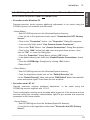
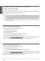
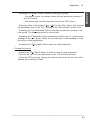
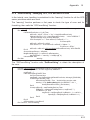
Client
Server
Read (PLC@ no.1,"Pump",...)
OLE
Automation
Clients
applications
OLE
Automation
Interface exposed
OFS
Pump, %MW1
Write (PLC@ no.2,"%MW0",...)
Valve, %MW0
PLC #2: Premium
PLC #3: Micro
PLC #1: Quantum
___________________________________________________________________________
1/1
ENGLISH
1.1
ENGLISH
The OFS server provides the interface between a group of PLCs and one or more
client applications in which the values of some of the data of these PLCs are to be
viewed and/or modified.
The main characteristics are :
• Multi-PLC,
• Multiple communication protocols,
• Multi-client,
• Access to variables via address or symbol,
• Local or remote access to server,
• Exposes its services via both the OLE Automation and OLE Custom interfaces,
• Compatible with the OPC standard Version 1.01a.
1.2
PLC Compatibility
The OFS server operates with the Schneider Automation TSX Micro and
TSX/PCX/PMX Premium PLC ranges (UNI-TE V2 communication protocol) as well
as the TSX Quantum, TSX Momentum and TSX Compact ranges (Modbus protocol).
The OFS server is not compatible with Series 7, Series 1000 Schneider
Automation PLC ranges or A-linie (AEG).
1.3
Communication Media Supported
The OFS server is compatible with the following media :
• UNI-TE V2 Prototcol :
- UNITELWAY,
- FIPWAY,
- ISAWAY,
- ETHWAY,
- XIPWAY.
• Modbus Protocol:
- Modbus+,
- Modbus TCP/IP.
___________________________________________________________________________
1/2
Section 22
Installation
2 Installation
Contents of the Product
ENGLISH
2.1
The OFS product comprises :
• One CD-ROM with setup instructions,
• Product Code ID.
Depending on your Product Code ID, the CD ROM may give you access to :
• The OFS server,
• The OFS simulator,
• The OFS Configuration Tool,
• XWAY Drivers,
• Documentation,
• Sample of Symbol Tables,
• OPC Clients :
- Tutorial Client in Visual Basic (including source code),
- Tutorial Client in C ++ (including source code),
- Test Client in Visual Basic (not supported*),
- Test Client in C ++ (not supported*),
- Test Client in HTML (not supported*),
- Test Client in Excel (not supported*).
Note :
The OFS product does not contain any cable for communication between the PC and
the PLC.
Note (*) :
The term "not supported" means that Schneider Automation does not provide any
technical support for these tools and examples.
Note :
The documentation is in Acrobat Reader format (pdf file). If you don’t have this tool already
installed on your machine, it is given on the CD in the Redist\Acrobat directory.
___________________________________________________________________________
2/1
ENGLISH
2.2
Hardware and Software Configuration
Configuration for NT 4.0 and Windows 95 :
• Pentium 133 MHz (minimal configuration), Pentium 166 MHz (standard configuration) ,
• 32 Mb of RAM.
Recommended configuration for NT 4.0 :
• Pentium 200 MHz,
• 48 Mb of RAM for executing the client application,
• 64 Mb of RAM for developing the client application.
The OFS product requires a PC "Wintel" platform : Intel x86 processor with either of the
following Microsoft Windows 32-bit operating systems :
• Windows 95 upgraded with Service Pack 1 (or later) with the DCOM option ,
• NT 4.0 upgraded with Service Pack 3 (or later).
Note :
The DCOM option is necessary under Windows 95 even for running the OFS server
locally. The DCOM version required is version 1.1 (or later) and is included on the OFS
installation CD-ROM. To install DCOM, follow the instructions given in the ReadMe.txt file
on the installation CD-ROM in the Redist\W95\dcom directory.
Note :
The OFS product is not compatible with a RISC platform, in particular with NT 4.0
on a Digital Alpha processor.
To determine which version of Windows and which service pack is installed on your
PC :
• Windows 95
Open the Control Panel, then click on the "System" icon, the displayed page shows your
system version :
- 4.0.950 = no service pack installed - install service pack 1,
- 4.0.950a = service pack 1 is installed, click on OK,
- 4.0.950b = service pack 2 is installed, click on OK.
To verify that DCOM is installed, Open the Control Panel, then click on the “Add/
Remove Programs”.
If DCOM is installed, you should find a line : “ DCOM for Windows 95 ”.
If you don’t have this line and you are sure that DCOM is installed (for instance
because you installed Internet Explorer 4.0) go on and ignore the installshield warning.
Otherwise you should install DCOM option before installing the server.
___________________________________________________________________________
2/2
2
To install DCOM, follow the instructions given in the ReadMe.txt file on the installation
CD-ROM in the Redist\W95\dcom directory.
• Windows NT
Open Programs\Administrative Tools\Windows NT\Diagnostics - your system version
is displayed, it should be at least :
- Version 4.0 (Build 1381: Service Pack 3).
Under NT4.0, DCOM is always installed.
___________________________________________________________________________
2/3
ENGLISH
Installation
ENGLISH
2.3
Installation Procedure
Foreword :
Under NT 4.0, it is necessary to have sufficient administrator rights before executing the
installation program (see Section 2.4).
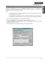
The installation procedure for the OFS product is as follows :
Insert the CD-ROM in the CD drive. The CD is Auto-run, therefore if your PC is set up for this
feature you should see the OFS main window as shown below. If Auto-run is disabled or doesn't
work :
• Click on the Start button in the taskbar,
• Select Settings -> Control Panel then click,
• Click on the Add/Remove Programs icon in the Control Panel,
• Click on the Install/Uninstall tab then click on the Install button and follow the
instructions,
• The Install Tool will automatically find the OFS Setup program on the CD, display the path
and file name then prompt you to conclude the installation.
The window shown below is displayed showing the OFS installation options.
The first thing to do is to enter into the dialog box either your CD-KEY or the word
DEMO in uppercase (the CD-KEY is your product-ID, located on a piece of paper
included with the CD-ROM).
The following components may be installed (depending on your CD-KEY) :
- OFS Configuration Tool,
- OFS Server,
- XWAY Drivers :
UNITELWAY,
FIPWAY,
ISAWAY,
ETHWAY,
XWAY TCP/IP.
___________________________________________________________________________
2/4
2
ENGLISH
Installation
Note :
The above components must be installed in the order of Configuration Tool, Server,
Drivers.
1. Click on the black button labelled Configuration tool,
• Follow the messages which appear on the screen to perform the installation.
• At the point where the installation program prompts for a directory, the default
directory is C:\Program Files\Modicon Telemecanique.
Note:
During installation of theOFS Configuration Tool underWindows 95, the following
warning may be displayed :
"Setup cannot continue because some system files are out-of-date on your
system. Click on OK if you would like setup to update these files for you now. You
will need to restart Windows before you can run setup again.
Click Cancel to exit setup without updating the system files".
- Click the OK button,
- Reboot when the system prompts you to,
- Restart Windows 95 and install the OFS Configuration Tool again.
2. When installation of the Configuration Tool is complete, the installation start-up
screen is once more displayed - now click on Server,
• Follow the messages which appear on the screen to perform the installation.
• The installation program offers the following options :
- Installation and parameter definition for the client and server stations :
- Installation (under "SERVER" directory) of the server for local AND remote
operation,
- Definition of the client station parameters for remote operation with
the server.
If this option is chosen, setup prompts for the name of the remote client (\\<name of machine>). The remote client name may be entered in plain text,
as a TCP/IP address (eg. 139.160.218.102) or as a Domain Name System
(DNS) name.
Note :
To change from one type of installation to another, simply restart the installation
program.
___________________________________________________________________________
2/5
ENGLISH
- Optional installation (under "TUTORIAL" directory) of the Visual Basic and
C++ tutorials,
- Optional installation (under "NOTSUP" directory) of the programs which are
not supported (see Section 2.1),
- Optional installation of direct link to Concept V2.1 Programming Workshop
(Concept is a programming tool from TSX Quantum, TSX Monentum PLC
range). Setup verifies the presence of the Concept Programming Workshop
on the machine in the indicated directory.
Note :
Since the Configuration Tool and the VB tutorial programs were written using Visual
Basic V5, any version of Visual Basic subsequently installed should be V5 in order
to avoid compatibility problems.
Comment :
When executing the installation program under Windows 95, messages indicating
problems with version and corruption of Windows system DLL may appear (for
example : COMPOBJ.DLL, DDEML.DLL).
These messages should be ignored (Windows 95 automatically corrects
these problems), as they do not affect operation of the terminal.
3. To uninstall the OFS product, open "Add/Remove Programs" in the Control Panel,
and delete "OFSconf V x.y.z IE xx" and "OPC Factory Server" as required.
Notes :
- In the case of an upgrade from a previous version, first uninstall the old version
and then install the new one. Performing an uninstall does not affect the parameter
configuration data.
- Some problems may arise if the path of the destination directory (directory where
the Server and Configuration Tool are to be installed) is too long and the hard drive
on your PC has been converted from FAT to NTFS. In this case, try to use short
file names.
e.g.
C:\OFS - instead of
C:\Program Files\Modicon Telemecanique\OFS
In particular, avoid spaces in file names.
___________________________________________________________________________
2/6
2.4
2
Defining the Parameters for Local or Remote Operation
The OFS server can operate in local and remote modes.
• Execution under Windows 95
Remote execution mode requires additional adjustment to be made using the
DCOMCnfg.exe tool available from Microsoft.
- Server Station :
- Start DCOMCnfg.exe from the Windows\System directory,
- From the list in the Application folder select "Schneider-Aut OPC Factory
Server",
- Click on the "Properties" button - the "Properties" Dialog Box appears,
- In the security folder select "Use Custom Access Permission",
- Click on the "Edit" Button - the "Access Permissions" Dialog Box appears,
- Click on the "Add" button then add users and grant them access - then
click on "OK" to close the Dialog Box,
- Close the “Properties” Dialog Box by clicking “OK” button.
- In the default security tab, check the «Enable Remote Connections» check
box
- Close the «DCOMcnfg» Dialog Box by clicking «OK» button.
- Reboot the PC
- Client Station :
- Start DCOMCnfg.exe from the Windows\System directory,
- From the Application folder click on the "Default Security" tab,
- In the "Default Security" folder click on the "Edit Default" button then edit/add
users and access rights. Close down the tool as above.
• Execution under NT 4.0
Remote execution requires additional adjustment
DCOMCnfg.exe tool supplied with NT 4.0.
to be made using the
These configuration settings must be made while logged on to the machine with an
account having the necessary administration rights to give access and execution
permission to the Server station.
- Server Station :
- Start DCOMCnfg.exe from the Windows\System32 directory,
- From the list in the Application folder select "Schneider-Aut OPC Factory
Server",
___________________________________________________________________________
2/7
ENGLISH
Installation
ENGLISH
- Click on the "Properties" button - the "Properties" Dialog Box appears,
- Click on the "Identity" tab and select "The Interactive User",
- In the security folder, select "Use Custom Access Permission",
- Click on the "Edit" button, the "Acces Permission" dialog box appears,
- Click on the "Add" button, add users and grant them access,
- Click on "OK" to close down the dialog boxes,
- Select "Use Custom Execute Permission",
- Click on the "Add" button, add users and grant them access,
- Click "OK" to close down the dialog boxes.
Note :
The following parameters (default parameters) must be defined in the "Default
properties" tab :
- Option : "Enable Distributed COM on this computer" checked,
- Field : "Default Authentication level" set to "Connect",
- Field : "Default Impersonation level" set to "Identify".
- Client station :
To give access rights to the server from the client station :
"Default security" tab, select the rights for access and execution.
• Summary of OFS Server remote operation
OFS server
on Windows 95
OFS server
on NT 4.0
Client application on Windows 95
YES
YES
Client application on NT 4.0
YES
YES
Notes :
- Under Windows 95, the OFS server must be started manually before any connection
attempt from a remote client.
- When the server is running under Windows 95, in case of connection problems, it may
be useful to modify the check box about DCOM security in the misc tab of the configuration
tool (see 3.8).
___________________________________________________________________________
2/8
Section
Configuration
Tool 33
3.1
Description
The OFS Configuration Tool is an essential component of the OFS product. It
enables the user to configure the OFS server and its simulator to interface with
Networks, Devices and Symbol Tables.
Notes :
- All modifications to the Server configuration are static - for them to take effect, the Server
must be shut down and restarted.
- All modifications are made in real-time in the Windows registry. You can follow what is
being modified reading the status bar. You don’t need to quit the software to validate.
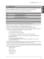
To run the OFS Configuration Tool, proceed as follows :
• Click on the Start button in the taskbar, then move the pointer to
"Programs"\"Modicon Telemecanique"\"OFS Configuration Tool" and then click
the left hand mouse button,
• The Configuration Tool main window opens as shown below,
___________________________________________________________________________
3/1
ENGLISH
3 Configuration Tool
ENGLISH
The OFS Configuration Tool window comprises a Menu Bar, with a Tool Bar under,
and eight Page Tabs. These are :
• Server
: access to debug interface, customize shutdown procedure, define
trace log,
• Symbols
: define the file extension of symbol table recognized by the server,
• Alias
: define alias on driver, PLC address, symbol table,
• Analog
: define analog type for dead banding,
• MB serial
: future extension to parameter serial ports for ModBus serial protocol,
• Misc.
: miscellaneous parameters,
• Simulator
: rule of evolution of simulated variables for the simulator
OFS_simu.exe which shares all other parameters with the OFS.exe
product,
• Advanced : server advanced parameters.
Each Tab accesses a page of configuration options. There is no default Tab, the
active Page is the last one used. The functions of each Page are now described in
Left-to-Right order.
Note :
All Icons, Buttons, Checkboxes, etc. are provided with "Tool Tips".
___________________________________________________________________________
3/2
3.2
3
Server Tab
Within the "Server" Page Tab, the user may enter or modify parameters for Server
Debug Window Start-up, Server Shutdown or Log Trace Files.
In the "Debug Interface" frame, there are two Option Buttons to define server startup parameters :
• Active,
• Not Active.
The default setting is "Not Active" meaning that the server appears only as an icon in
the taskbar. When in this state, you cannot open the server window, i.e. you cannot
access the server debug features.
If you want to know what is appended when the server is started and when your client
application calls each OPC interface, you need to activate the server debug interface.
Note however, that this option is reserved for advanced users, since you could modify
the state of an OPC group without using the dedicated interface from the client
application. Above the "Active" Option Button, there is an empty location for a
hidden button. Add the "/HIDE" option in the OFSconf.exe shortcut, if you wish to
show the "Hidden" Option Button.
How to add an option will be discussed in section 3.12 "OFSConf options".
The "Hidden" option hides the server (no window, no icon in the taskbar). This could be
useful if you don’t want the end user to be able to close the server during a session.
The user then has no means of knowing if the Server is running except, under NT
only, using the Windows NT Task Manager (press shift + ctrl + esc), "Processes" tab,
search OFS.exe.
Within the "Shutdown" frame, you can customize the server shutdown procedure.
Typically, this is useful in a DCOM environment with remote clients, to warn each
client that the shutdown procedure is in progress. Each client must be properly
disconnected from the server before the end of server shut-down else the link with the
server will be lost.
The Shutdown Batch File offers the user the means to perform certain pre-programmed
actions before Server shutdown (e.g.: send message warning Client of imminent
shutdown).
The supplied batch sample :
"C:\Program Files\Modicon Telemecanique\OFS\Server\shutDown.bat"
demonstrates how to send a message to a remote client PC under NT. You need to
customize this batch (edit it under NotePad) to indicate the name of the remote
computer on your network.
___________________________________________________________________________
3/3
ENGLISH
Configuration Tool
ENGLISH
A Shutdown Batch File name may be entered in the Text Box provided or found using
the Browse facility, (the yellow "open" toolbar and the "open" menu become available
when you focus on the pathname type textboxes). An alternative way is to drag and
drop a batch file from Windows Explorer to OFSconf.exe
To enter text from the keyboard, place the pointer in the Text Box and click. The
pointer changes into the familiar text entry cursor. Validate your choice by clicking
the "OK" button to the right of the Text Box.
Additionally, a Shutdown Counter is provided where a numeric delay in seconds before
the batch file is executed, may be entered. This counter is only used if a shutdown
batch file name has been specified. Default setting is 10 seconds.
The "Log Trace" frame offers the user the possibility to store debugging traces in a file.
Three Text Boxes for pathnames are provided for entry of Log Trace File names used
in Debug, Xway or Modicon protocols respectively.
An option is also provided in the form of a checkbox whether to overwrite the previous
log file. If selected of course, the contents of the previous log file are lost.
The "OPC spy mode" when checked, offers an enlarged option for debugging traces.
"Debug trace SDK symb" is associated with symbol management.
"Debug trace SDK opt" is associated with communication requests.
After server start-up, you can dynamically overwrite those options for the current
server session only, via the "Misc.", "Spy mode", "Debug Symbol" and "Debug Request"
menus, available when the "Debug Interface" is activated.
___________________________________________________________________________
3/4
3.3
3
Symbols Tab
Within the "SYMBOLS" page, the user may define or edit the link between a Symbol
Table file extension and Symbol Table file format recognised by the server.
By default, the grid is automatically populated with the following :
SUFfix
Type of symbols table file
SCY
PL7 exported symbols table file
FEF
PL7 exported application file
TXT
ModSoft exported symbols table file
PRJ
ConCept project file
CCN
ConCept exported symbols table file
CSV
Comma Separated Values file
To define or edit an extension (generally three letters without a dot) :
• Double click on an empty or occupied field respectively in the "SUFfix" column. A
Dialog Box opens prompting you to enter/edit a file extension,
• Click on "OK" - the file extension is entered/modified in the selected field,
• Double click on the corresponding field in the "Type of Symbol Table file" column. A
List Box opens displaying the available file formats. These are :
1. PL7 exported symbol table file,
2. ConCept exported symbol table file,
3. PL7 database (not available for the first version of the product),
4. ConCept database (requires the ConCept OFS Programming Workshop
installed on the PC),
5. Modsoft exported symbol table file,
6. Comma Separated Val (comma, space or tab separator in a text file
generated by MS Excel).
• Click on your choice of file format, then click on "OK" - the chosen file format is then
entered in the selected field of the "Data base or neutral file" column.
• A click of the right mouse button displays a pop-up menu of supplementary editing
options which change according to which zone of the page the pointer is positioned.
The full complement of options are:
- Sort the column,
- Add an item,
- Modify this field,
- Delete all the row,
- Erase field(s).
___________________________________________________________________________
3/5
ENGLISH
Configuration Tool
ENGLISH
Note :
Do not specify the dot separator to the left of each extension.
In the "Consistency appli. in PLC / Symbols file" frame, you can specify what level
of safety you want for the coherence between the symbol tables and the application
in the PLC :
• Strict level
: on difference, the connection with the device will be rejected,
• Read only level : on difference, the device will be in read only mode,
• Warning level
: on difference, a warning is returned to the client application.
___________________________________________________________________________
3/6
3.4
3
Alias Tab
The "Alias" page allows the user to define/edit a label corresponding to a network
driver, a PLC address and, if it exists, the symbol table of the variables used.
To define/edit an Alias :
• Double click on an empty or occupied field respectively in the "Alias" column. A
Dialog Box opens prompting you to enter or edit respectively the Alias string,
• Click on "OK" - the Alias string is entered/modified in the selected field,
• Double click on the corresponding field in the "<driver>:<PLC addr>" column. A
Dialog Box opens, displaying a list of Alias drivers and prompts the user to choose
one and enter/edit the corresponding PLC address. If the Alias driver is for a network
using TCP/IP, the option is also given to enter/edit a DNS name. In this case, it is the
definition entered/edited last (DNS or definitive PLC address) that appears in the
selected field of the "<driver>:<PLC addr>" column on clicking "OK". For MBT, an
additional "Bridge" index could be entered.
A PreLoaD option (PLD Column) exists for the case when a symbol table is very
large and would normally take several minutes to load. When selected (by entering
a 1 in the "PLD" column), the Preload option causes the symbol table to be loaded
at Server start-up and no longer at the first creation of an item for the device. The
Preload option is disabled by entering "0" (zero) or by deleting the content of the
cell in the "PLD" column.
Symbol tables may be defined by their entire path name or just by a file name which
has been previously defined in a Default file folder. The Default file name and path may
be entered from the keyboard in the Text Box provided, it may be browsed or located
with the Windows Explorer then "Dragged and Dropped". Click on the "OK" button to
validate.
Aliases may be created dynamically by a special tool - the "Extra Dynamic Alias" Text
Box allows the user to define the number of entries available for extra Aliases. Enter
the desired number in the Text Box and click on the "Extra Dynamic Alias OK" button
to validate. Default is 5 extra aliases.
The last column, "Comment", allows optional entry of a comment associated with an
alias.
• A click of the right mouse button displays a pop-up menu of supplementary editing
options which change according to which zone of the page the pointer is positioned.
The full complement of options is :
- Sort the column, Add an item, Modify this field, Delete all the row, Erase
field(s),
- NotePad (to be used on text files only).
___________________________________________________________________________
3/7
ENGLISH
Configuration Tool
ENGLISH
• The "Options" > "Preload all" allows checking of the PLD column for each alias
having a symbols table. Click again on the menu to uncheck the menu and reset the
PLC column.
We recommend the defining of aliases if the end-user wishes to use the OPC browse
feature which shows the symbols to be entered in the OPC groups directly from the
client application.
Note :
It is not recommended to use more than one alias, simultaneously, for the same device with
an associated symbol table. Only the symbol table of the first alias used for that device will
be loaded into memory.
___________________________________________________________________________
3/8
3.5
3
Analog Tab
The "Analog" page is used for "Deadbanding" purposes. It permits the user to
define a Variable Range Label and assign minimum and maximum values to it. For
each value, the Deadband is a percentage of the range assigned to that value. The
Deadband percentage is a Group attribute and serves to filter the notification of
when a float value changes.
To define/edit a Variable Range Label :
• Double click on an empty or occupied field respectively in the "Analog Type
Name" column. A Dialog Box opens prompting you to enter or edit respectively,
the label string,
• Click on "OK" - the label string is entered/modified in the selected field,
• Double click on the corresponding field in the "LOW Eng. Unit" column. A Dialog
Box opens, prompting the user to enter a numeric value corresponding to the low
end of the range,
• Double click on the corresponding field in the "HIGH Eng. Unit" column. A Dialog
Box opens, prompting the user to enter a numeric value corresponding to the
high end of the range. Click on "OK" to finish.
Note :
The Configuration Tool will not permit a value less than that entered in the "LOW
Eng. Unit" field, to be entered in the "HIGH Eng. Unit" field.
• A click of the right mouse button displays a pop-up menu of supplementary
editing options which change according to which zone of the page the pointer is
positioned. The full complement of options is :
- Sort the column,
- Add an item,
- Modify this field,
- Delete all the row,
- Erase field(s).
• Click on the desired option to perform the action on the selected field.
Example of analog type :
Analog Type Name
LOW Eng. Unit
HIGH Eng. Unit
AnalogType
-1.5
+2.4
___________________________________________________________________________
3/9
ENGLISH
Configuration Tool
ENGLISH
3.6
MB serial Tab
Since the first version of OFS does not provide the support of ModBus serial
protocol, this tab is a future extension that allows parameter definition of the four
serial ports COM1 to COM4.
3.7
Simulator Tab
The Simulator is merely an instance of the Server running without any real devices
connected. It is used typically in the DEMO version of the product.
A number of controls are provided for configuring the Simulator operation.
• In the "Simulator tuning" frame :
- Factor : relates to the time period by which variables are updated. If set to "1"
(the default value), simulated variables are modified at the update rate of the
group and each time a "read device" is performed (Synchronous or Asynchronous).
If set to "N" (where N is an integer value greater than 1), there would be one
chance in N that the simulated variable would be modified. Enter a positive
numeric value in the Text Box and click the "Max Value" button to validate.
- Max Value : indicates the maximum value for the simulated variables.
• In the "Initialization Values" frame :
When started, the Simulator initializes variables according to how the following
mutually exclusive Option Buttons are set :
- Random : if selected, the Simulator variables are initialized to random values
not exceeding the value entered in "Max Value",
- Not random : if selected, all variables are initialized to zero and on incremented
1 by 1 to maxi value.
___________________________________________________________________________
3/10
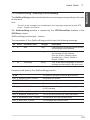
3.8
3
Misc. Tab
The "Miscellaneous" page presents a number of operational features which may be
enabled/disabled by checking the corresponding Checkbox.
• In the "Features" frame these are :
- Change PLC status : when checked, allows the Server to change the operating
mode of the PLC (eg. RUN -> STOP or STOP -> RUN) else the client application
will receive the "EOL_E_FEATURE_DISABLED" error : This feature has been
disabled by the administrator,
- DNS scanning : when checked, authorizes the Server to use DNS to identify
PLCs,
- Change Activity : when checked, authorizes the active attribute of an item or
group to be modified from the Server Debug Interface. For safety reasons, you
may wish to disable this option. In that case, only the client application can modify
the active property of the group,
- OPC Extensions : when checked, authorizes use of Schneider Automation
OPC extensions and custom interfaces, designed by Schneider and not part of
the OPC Specification,
- DCOM Security : when checked, DCOM security is active. In case of a problem
of remote connection with DCOM, it may be useful to disable the DCOM security
in order to gain free access to the OPC Factory Server,
- Verify Devices : when checked, verifies that a device is connected when a
variable for it is created, for the FIRST TIME ONLY. Else the device presence
verification will be postponed to the reading or writing of the variable,
- Dynamic Config : allows dynamic configuration without restarting the server.
When checked, the external tool :
C:\Program Files\Modicon Telemecanique\OFS\Server\STLoader.exe,
Can be started to refresh symbol tables and dynamically create extra aliases
according to the number specified in the Extra Dynamic Alias number in the
"Alias" tab.
• In the "Group" frame these are :
- Min Update Rate : the "Group" Text Box allows the user to specify a numeric
value in ms, for the minimum update rate of a variable,
- Enter the value in the Text Box, then click on the "Min Update Rate" button to
validate. Default setting is 500 ms.
___________________________________________________________________________
3/11
ENGLISH
Configuration Tool
ENGLISH
3.9
Advanced Tab
A number of options are offered for advanced users.
• In the "Time-out" frame :
- The ModBus and Unite Text Boxes allow the user to enter a positive numeric
value in milliseconds. for the respective device time-outs. Enter the value and
click on the corresponding "OK" button to validate. Default setting is 1000 ms. for
both time-outs.
• In the "Avoid driver contention" frame :
- Max. Pending Req. : is the value of the maximum number of messages that
may be queued for a device. Enter the value and click on the "MaxPendingReq."
button to validate. Default setting is 20.
• In the "Impact on the CPU loading" frame on the "server" machine :
- XwayRec Rate : This parameter is specific to the XWAY network. It is the
numeric value in milliseconds, at which the message reception task is executed
(typical value - 50 to 100). Too small a value increases the CPU overhead. Enter
the value and click on the "XwayRcvRate." button to validate. Default setting is
100 ms.
3.10 GUI : Menus, Tool Bar and Status Bar
The Menus and Toolbar of the OFS Configuration Tool contain the usual copy, cut,
paste, toolbar buttons plus some additional ones :
• RegEdit : the system editor for the registry. See the "caution" reminder in the
next chapter. RegEdit gives complete access to the registry. OFSconf is a registry
editor only, dedicated to OFS,
• The "Open" toolbar is available only on "pathname" type textboxes,
• DCOM : the DCOM drop-down menu offers the facility to verify if DCOM is
installed on your PC under Windows 95 and if so, to run the DCOM Configuration
Tool (can also be run from an icon). Under NT4, DCOM is installed by default,
• Print : prints the current configuration in a text file (can also be run from an icon),
• Options : offers various page alignment and resizing options on the grid,
Some standard icons are also provided :
• NotePad : runs the Windows NotePad accessory. Useful to edit Symbol Table
files and Log trace,
• Calc : runs the Windows Calculator accessory for convenience.
___________________________________________________________________________
3/12
3
In the status bar, before the date, there is a counter of missing mandatory
information in a grid or in a textbox. If you quit the software without fixing the
missing data displayed in red with the label <mandatory>, a warning is displayed. It
is recommended that the counter be maintained at zero else the server could fail.
A warning is also displayed if you forget to validate the new value in a textbox by
<enter> or by clicking on the "OK" button.
3.11 Saving/Restoring Configuration
You need to run RegEdit, the system utility which allows the user to view the
Windows registry directory for the OFS and/or copy it to another PC.
To copy or save the configuration data :
1. Click on the "RegEdit" icon - the Registry Editor Window opens.
configuration data are stored under the following Registry key:
All
HKEY_CURRENT_USER\Software\Schneider Automation\OpcSrv
Explore the path shown above until the branch is completely open.
Click on the "Registry" menu and from the drop-down, click on "Export Registry File".
A Dialog Box opens,
2. Click on "Selected Branch" in the "Export range" frame, then enter the
destination path and file name with a .reg extension and "Save",
3. Transfer the file to the destination PC, then double click on the .reg file. The
destination PC registry data is then updated.
Caution:
Be careful! Any modifications in the registry should be done by advanced users only. There
is no "undo" and it’s possible to crash your PC if you accidentally modify or delete a wrong
key.
___________________________________________________________________________
3/13
ENGLISH
Configuration Tool
ENGLISH
3.12 OFSconf Options
The OFSconf options can only be set in the shortcut.
METHOD :
1.
"Start" > "Settings" > "Taskbar & start menu",
2.
Click "Advanced" button,
3.
Go to C:\WINNT\Profiles\All Users\Start Menu\Programs\Modicon\Telemecanique\OFS
Configuration Tool.lnk,
4.
Right-click > "Properties", 2nd tab "Shortcut",
5.
Go to the field :
Target = "C:\Program Files\Modicon Telemecanique\OFS\OFSconf\OFSconf.exe"
6.
Add the option after the last quote which appears only if there are space(s) in
a long name,
7.
Click "Close" button.
Example:
Target = "C:\Program Files\Modicon Telemecanique\OFS\OFSconf\OFSconf.exe" /HIDE
Note :
Do not forget the space separator before the slash of each option.
Known options :
• /HIDE
show "hidden" option in the "Server" tab: hide the server icon.
• /RESET
reinitialize all the parameters in the registry. Be careful! This means
that you lose all your previous configuration.
___________________________________________________________________________
3/14
4
Functions of the Section
Product 4
4.1
Definition of a Group of Items
All of the services of the OFS product are based on the concept of a group of
items : a group of variables of any PLC which can be accessed either by their
addresses or by their symbols.
• It is possible to define several groups,
• A group may concern several PLCs : each item may have a different PLC address,
• A group concerns various communication media and PLCs : each item may refer
to a different communication driver. If a PLC can be accessed via several
communication media, it is possible to mix variables addressed via different media
within one group,
• A group can be made up of different types of item : it is possible to mix all the
types of object managed by the OFS server,
Example :
Mixing words, double words and floating points within one group.
• Depending on the service called, a group is transcribed on one or more communication requests,
• All items in the same group share the update rate and deadbanding percentage.
4.2
Synchronous Services : Read / Write
• These services are used for partial or complete reading or writing of a group of
items.
• The periodic scanning of the evolution of variables (read polling) must be handled
by the client application.
• The term "synchronous" means that the client application which calls up these
read or write services is blocked for the time during which the result is being
obtained. The instruction which follows a synchronous read or write call in the
code of the client application will only be executed when all the communication
requests corresponding to that call have been processed. This term does not
mean synchronization with the PLC. It means that, during a synchronous read
operation, the OFS server does not guarantee that all the variables in a group
will be read in the same PLC scan if this group is transcribed on several
communication requests. The OFS server provides a mechanism for ascertaining
the number of requests necessary to read the whole of a group of items (only for
synchronous groups).
Note :
The conditions ensuring that the items in a group are consistent with one another (read
or written in the same PLC scan) are described in Sections 6.5 and 6.6.
___________________________________________________________________________
4/1
ENGLISH
4 Functions of the Product
ENGLISH
4.3
Asynchronous Services
• These services are used for partial or complete reading or writing of a group of
items.
• The periodic scanning of the evolution of variables (read polling) must be handled
by the client application.
• The client application is not blocked for the time during which the data are being
obtained.
• The results values are notified to the client using the notification mechanism (this
latter should be enabled).
• For the synchronization with the PLC, everything discussed for synchronous
services is valid (see 4.2).
___________________________________________________________________________
4/2
4.4
4
Periodic Read Service
The periodic scanning of variables : read "polling" and the notification of the
change of their value are handled by the OFS server.
• The client application must program a function called "WakeUp", on which it will
be informed (notified) by the OFS of the changes in value which have occurred on
the items of all the groups which are scanned periodically.
This means that the "WakeUp" function is unique in the client application : it
receives all the notifications from the OFS server, then it must redistribute them to
the processing functions specific to each group which is scanned periodically.
Note :
For ready-to-run supervisory software, the “WakeUp” function should be preprogrammed. If it is not the case, the notification mechanism may not be used.
The name of this "WakeUp" function is set by the OPC standard : OnDataChange.
Warning :
Processing which takes up a significant amount of CPU time (eg : display
which is too complex) should not be performed in the "WakeUp" function, as
this may adversely affect the performance of the Operating System.
• The OFS server performs the notification by group, and not individually by item.
This means that, for a given group, the OFS server transmits the list of items
whose value has changed to the client application "WakeUp" function.
In the case of a table type item, the OFS server transmits the whole table even if
only a subset of the elements has changed in value.
The following concepts are associated with the periodic read service :
• Assignment of a scanning PERIOD ("RATE") to a group : time between two read
operations during the "polling" performed by the OFS server. This concept reflects
the need to monitor the variables at different rates.
Example :
Display the PLC time every second, and display a temperature every minute.
• Assignment of DEAD-BANDING to a group : filtering of the notifications when
the values of the variables of the group change. The notification takes place if, at
the end of the group scanning period, variables have changed by more than a
certain percentage with respect to their old value (see Section 6.9 for the use of
dead-banding).
Example :
Inform the client application only if temperatures have changed by more than
10%.
Note :
Dead-banding is only applied to floating point variables.
The purpose of these two concepts is to be able to control (limit) the flow of the
notifications
sent to the client application, to avoid saturating the system.
___________________________________________________________________________
4/3
ENGLISH
Functions of the Product
ENGLISH
4.5
Mechanism for Adjusting the Communication Time-Out with a
Device
This mechanism enables the user to view or modify the communication time-out
with a given device. This time-out is the period during which the OFS server waits
for an answer from a given device after sending it a request.
The default values can be set using the configuration tool (see 3.9). These defaults
values apply either to all XWAY devices or all MODBUS devices.
Modification of the time-out for a given device is possible using a specific item (see
6.10).
4.6
Mechanism for Managing the PLC Operating Mode
This mechanism enables the user to view or modify the operating mode of a PLC :
Run, Stop and Init.
Note :
The OFS server only provides the basic service for changing the operating mode of a
PLC. Since the change of state of the PLC may have repercussions on the process, all
the preliminary checks are the responsibility of the client application.
Example :
Programming a message in the client application requesting the operator to confirm the
change of the PLC operating mode.
___________________________________________________________________________
4/4
Functions of the Product
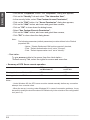
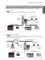
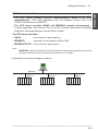
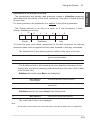
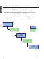
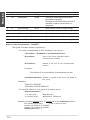
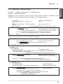
Mechanism for Accessing the OFS Server
ENGLISH
4.7
4
There are two methods of accessing the services provided by the OFS server.
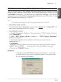
• Local access
The client application and the OFS server are on the same station.
OFS station
DatasSymbole.SCY
(Concept, PL7)
Locate
Client
Application
Data2.ASC
(Modsoft)
MODBUS Network
XWAY Network
• Remote access via DCOM
The client application and the OFS server are on separate stations, connected
via the Microsoft TCP/IP network :
Ethernet TCP/IP Network
DCOM
OFS station
Client station
Remote
Client
Application
Locate
Client
Application
MODBUS Network
DatasSymbole.SCY
(Concept, PL7)
Data2.ASC
(Modsoft)
XWAY Network
___________________________________________________________________________
4/5
ENGLISH
4.8
Symbolic Support
Symbolic support enables the replacement of the address of any variable in the
item definition, by it's name in the PLC application (ex: use "Symb1" instead of the
Xway address "%MW1" or instead of the Modsoft address "400001"). It is handled
as a string substitution and has no effect on Read/Write operations.
The supported symbol table formats are:
• PL7 exported symbol table file,
• Concept exported symbol table file,
• Modsoft exported symbol table file,
• CSV symbol table file (Excel exported format).
For more detail, see 6.13
4.9
Browse Support
The OPC Browse Interface is supported by the OFS product. This enables users
to browse symbols available for a given PLC, provided that the OPC Client used,
supports the Browse interface. This is an easy way to determine which variables
can be created for a given device.
Note :
Only PLCs declared with the Configuration Tool and associated with a Symbol Table can
be browsed.
4.10 Concept Link
The direct link with the Concept database enables :
• Symbolic Support,
• Browse Support,
• Access to unlocated variables and to structured data.
Concept and OFS can run simultaneously on the same Concept project. More than one Concept
project can be open at a time (see 6.16).
___________________________________________________________________________
4/6
4
4.11 Simulator
The Simulator enables testing of the application without the actual devices. It provides
a simple animation of all created variables. Except for device access, it is identical
to the actual Server.
Note :
The only restriction is that it does not support writing to array items.
___________________________________________________________________________
4/7
ENGLISH
Functions of the Product
ENGLISH
___________________________________________________________________________
4/8
Section
5
Type of variables handles by the
server 5
Preface :
This section gives an exhaustive list of the various types of objects managed by the OFS
server, and indicates the access permitted for each type : read only (R) or read/write
(R/W).
The general syntax for an item is :
<item>::=<Driver Name>:<Device Address>!<Variable Definition>[:<array
length>[;<postfix>]]
The <Driver Name>:<Device Address> part can be replaced by an alias created
with the Configuration Tool (see 3.4).
If an alias is not used, Driver Name should be one value of the following list and the
Device Address is the address of the device on the communication medium :
Driver Name
Example of Device
Address
Communication Medium
UNTLW01
0.254.0
UNI-TELWAY
FIP01, FIP02
0.31.0
FIPWAY adapter 01 or 02
ISAWAY01, ISAWAY02
0.5
ISAWAY adapter 01 or 02
ETHWAY01
0.5
ETHWAY adapter 01
XIP01, XIP02, XIP03
0.5
XWAY TCP/IP adapter 01 or 02 or 03
MBP00,MBP01
PM.12 or DM.15.3
MODBUS+ adapter 0 or 1
MBT
139.160.218.102
MODBUS TCP/IP
The Variable Definition part can be either a variable address (see the "Syntax"
column in the other tables of this chapter) or a symbol (see 4.8).
For Modbus+ users, if you plan to use simultaneously Concept and OFS, use DM
paths. Otherwise you may not be able either to connect to the PLC with Concept or to
download your application.
For the variables that support this feature, the array length part enables the user to
create items that are actually arrays and gives the number of the array element.
The Postfix part can be R : R means READ-ONLY and is a way to create an item
that will always be considered as READ-ONLY.
For Modsoft variables, F and D postfix values are also supported (see 5.3).
___________________________________________________________________________
5/1
ENGLISH
5 Type of variables handles by the server
ENGLISH
Note :
The Driver Name, Device Address and Variable definition are mandatory.
The array length and the postfix are optional.
Examples :
"FIP01:0.31.0!%MW12"
"XIP02:0.5!%MW100;R"
"TSX2!Toto"
"XIP01:0.5!%MW100:10"
"MBP00:DM.1.2!400001"
"QTIP!Titi"
Note :
The MBT Device Address field uses a postfix of ";xx" to designate the destination index
used in the Modbus+ mapping table defined in the Ethernet to Modbus+ bridge. The "xx"
is the decimal value of the index. For example, "139.160.218.103;50".
___________________________________________________________________________
5/2
Type of variables handles by the server
PL7 Variables
ENGLISH
5.1
5
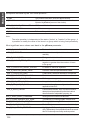
5.1-1 Standard Objects
• System objects :
Syntax
Access
TSX 37
PCX/TSX 57
System bit
Object
%Si
R[/W]
Y
Y
System word
%SWi
R[/W]
Y
Y
System double word
%SDi
R[/W]
Y
Y
Note :
Some of these objects can only be modified by the system : the PL7 workshop installation
manual indicates exactly the type of access (R or R/W) permitted for each of the system
objects defined.
• Memory objects (variables and constants) :
Object
Syntax
Access
TSX 37
PCX/TSX
Internal bit
%Mi
R/W
Y
Y
Internal byte
%MBi
R/W
Y
Y
Internal word
%MWi
R/W
Y
Y
Internal double word
%MDi
R/W
Y
Y
Floating point (32 bits)
%MFi
R/W
Y
Y
Constant word
%KWi
R
Y
Y
Constant double word
%KDi
R
Y
Y
Floating point
constant (32 bits)
%KFi
R
Y
Y
Common word on
network 0
%NW{j}k
j = station no.
k = word no.
R/W
Y
Y
Common word on
other networks
%NW{i.j}k
i = network no.
j = station no.
k = word no.
R/W
Y
Y
57
Note :
The OFS server does not permit direct access to word extract bits, unlike PL7 language.
To access a particular bit of a word, a client application programmed with the OFS server
must access the word using a read primitive and itself apply the "mask" necessary to
extract the required bit(s).
___________________________________________________________________________
5/3
ENGLISH
5.1-2 Grafcet Objects
Object
Syntax
Access
TSX 37
PCX/TSX
Step state
%Xi
R
Y
Y
Activity time
of a step
%Xi.T
R
Y
Y
State of a step
in a macro-step
%Xj.i
R
N
Y
Activity time of a
step in a macro-step
%Xj.i.T
R
N
Y
State of the IN step
of a macro-step
%Xj.IN
R
N
Y
Activity time of the
IN step of a macro-step
%Xj.IN.T
R
N
Y
State of the OUT
step of a macro-step
%Xj.OUT
R
N
Y
R
N
Y
Activity time of the OUT
step of a macro-step
%Xj.OUT.T
57
Note :
The macro-steps on available only on PCX/TSX 57 version 3.0 or later.
___________________________________________________________________________
5/4
Type of variables handles by the server
ENGLISH
5
5.1-3 Standard Function Blocks
Object
Syntax
Access
TSX 37
PCX/TSX
%Ti.V
R
Y
Y
Preset Value
%Ti.P
R/W
Y
Y
Done Output
%Ti.D
R
Y
Y
Running Output
%Ti.R
R
Y
Y
Current Value
%TMi.V
R
Y
Y
Preset Value
%TMi.P
R/W
Y
Y
Working Output
%TMi.Q
R
Y
Y
Current Value
%MNi.V
R
Y
Y
Preset Value
%MNi.P
R/W
Y
Y
Running Output
%MNi.R
R
Y
Y
Current Value
%Ci.V
R
Y
Y
Preset Value
%Ci.P
R/W
Y
Y
Empty Output
%Ci.E
R
Y
Y
Done Output
%Ci.D
R
Y
Y
Full Output
%Ci.F
R
Y
Y
Input Word
%Ri.I
R/W
Y
Y
Output Word
%Ri.O
R
Y
Y
57
PL7_3 timer : %Ti
Current Value
IEC 1131-3 timer : %Tmi
One-Shot : %Mni
Counter Up/Down : %Ci
Register : %Ri
Full Output
%Ri.F
R
Y
Y
Empty Output
%Ri.E
R
Y
Y
Full Output
%DRi.F
R
Y
Y
Number of current step
%DRi.S
R
Y
Y
Activity Length
%DRi.V
R
Y
Y
Drum : %Dri
___________________________________________________________________________
5/5
ENGLISH
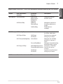
5.1-4 Table Objects
Reminders :
In read mode, the size of the tables is unlimited, except for bit tables (system and memory),
which are limited to 450 elements.
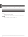
• Tables of system objects :
Type of element
Syntax
Access
TSX 37
PCX/TSX 57
Max. write
size
System bit
%Si:L
R
Y
Y
-
System word
%SWi:L
R[/W]
Y
Y
58
System double word
%SDi:L
R[/W]
Y
Y
29
Note :
Access to system objects using the table syntax constitutes an extension to PL7
language. The system objects defined in the TSX 37 and PCX/TSX 57 ranges are not all
consecutive, which may limit access using the table syntax in some cases.
• Tables of memory objects :
Type of element
Syntax
Access
TSX 37
PCX/TSX 57
Max. write
size
Internal bit
%Mi:L
R/W
Y
Y
450
Internal word
%MWi:L
R/W
Y
Y
58
Internal double word
%MDi:L
R/W
Y
Y
29
Floating point (32 bits) %MFi:L
R/W
Y
Y
29
Constant word
%KWi:L
R
Y
Y
-
Constant double word %KDi:L
R
Y
Y
-
Floating point
constant (32 bits)
%KFi:L
R
Y
Y
-
Common word on
network 0
%NW{j}k:L
j = station no.
k = word no.
R/W
Y
Y
4
Common word on
other networks
%NW{i.j}k:L
i = network no.
j = station no.
k = word no.
R/W
Y
Y
4
Character
string
%MBi:L
R/W
Y
Y
116
___________________________________________________________________________
5/6
5
ENGLISH
Type of variables handles by the server
Notes :
- Access to common words using the table syntax constitutes an extension to PL7
language.
- The address (i) and the length (L) of a character string %MBi:L must be even.
• Tables of Grafcet objects
Type of element
Syntax
Access
TSX 37
PCX/TSX 57
Max. write
size
Step state
%Xi:L
R
Y
Y
-
Activity time
of a step
%Xi.T:L
R
Y
Y
-
State of a step
in a macro-step
%Xj.i:L
R
N
Y
-
Activity time
of a step in
a macro-step
%Xj.i.T:L
R
N
Y
-
State of the IN step
of a macro-step
%Xj.IN:L
R
N
Y
-
Activity time
of the IN step
of a macro-step
%Xj.IN.T:L
R
N
Y
-
State of the OUT
step of a macro-step
%Xj.OUT:L
R
N
Y
-
Activity time of
the OUT step of
a macro-step
%Xj.OUT.T:L
R
N
Y
-
Note :
Apart from "step state", access to the other Grafcet objects using the table syntax
constitutes an extension to PL7 language.
Reminder :
The macro-steps are available only on PCX/TSX 57 version 3.0 or later.
Additional information about macro-steps tables :
• The syntax %Xj.i:L consists of reading several consecutive steps (number L) of the
macro-step (j).
Example : %X1.0:3 corresponds to %X1.0, %X1.1 and %X1.2.
• The syntax on a particular step (IN or OUT) of a macro-step (j) consists in reading
this step for several consecutive macro-steps (number L).
Example : %X1.IN:3 corresponds to %X1.IN, %X2.IN and %X3.IN.
%X1.OUT.T:3 corresponds to %X1.OUT.T, %X2.OUT.T and %X3.OUT.T.
___________________________________________________________________________
5/7
ENGLISH
5.2
Concept Variables
StateRam Objects
Range
Coils
0x
Input Status
Item Syntax
Access
Array
%Mi
R/W
%Mi:L
1x
%Si
R
%Si:L
Input Reg as UINT
3x
%SWi
R
%SWi:L
Holding Reg as UINT
4x
%MWi
R/W
%MWi:L
Holding Reg as UDINT
4x
%MDi
R/W
%MDi:L
Holding Reg as REAL
4x
%MFi
R/W
%MFi:L
IEC-1131
Symbols are supported everywhere and all variables are represented by symbols
since there is no address syntax in the Concept language.
As an extension to the Concept language it is possible to use (Located Variables
only) the IEC 1131 Syntax.
Example :
Variable "Toto", located on register 400023 can also be accessed by %MW23 (UINT)
or %MF23 (Real) or %MD23 (UDINT). For %MF23 & %MD23 registers 23 and 24 are
actuallyread. The syntax Toto:5 or %MW23:5 means an array of five registers starting
at Toto (=400023).
The structures are supported. It is possible to access a structure either as an array
of bytes (it is up to the user to know the internal fields and their type) or field by field
with the syntax :
<structure name>.<field name>
In that case, the server figures out the data type directly from the ConCept database.
Note :
Structure access may only take place with a device associated with a Concept project
file (*.prj) as a Symbol Table file. Both located and unlocated devices may be accessed
if the above is true.
To easily manipulate a structure, it is possible to create a group and into that group
to create an item for each field of the structure.
Notes :
- Access to unlocated variables and structures is ONLY possible if the IEC runtime has
been enabled into the PLC configuration.
- Moreover unlocated variables and structures should be really used into your PLC
application to be readable/writeable with OFS. Actually with Concept, any unused
unlocated variables is not known by the PLC.
___________________________________________________________________________
5/8
Type of variables handles by the server
ModSoft variables
ENGLISH
5.3
5
The Modsoft supported syntax is only long addresses (6 digits) for the moment.
Ex: 400001.
The following syntaxes are NOT supported (do not confuse with array syntax):
- 4:00001,
- 40001,
- 4x00001.
The access to any registers located into the 6x range-id is not possible.
The array syntax <reg number>:<length> is supported for range-id 0,1,3,4.
It enables you to read not only one register at a time but many registers (actually
<length> registers).
For Holding registers, it is possible to create an item as a Float or as a Long int
using a postfix of F or D. Two consecutive registers will be used. The usual R
postfix can be used at the same time.
Example :
400001;F
Float for registers 1 & 2.
400012;D
Long int (32 bits) for registers 12 & 13
400120;FR
Float considered as read-only for registers 120 & 121
Object
Range
Item Syntax
Access
Array
Max Size
Write
Coils
0
00000i
R/W
00000i:L
800
Input status
1
10000i
R
10000i:L
-
Input register
3
30000i
R
30000i:L
-
Holding register
4
40000I
R/W
40000I:L
100
Reminders :
In read mode, the size of the tables is unlimited, except for bit tables (system and memory),
which are limited to 2000 elements.
___________________________________________________________________________
5/9
ENGLISH
5.4
Local Variables
A pseudo-protocol (driver name: "LOCAL") is supported to enable the creation of
variables that are only local to the server (no relation with any hardware device).
Those local variables are always of type WORD (VT_I2), created with a name.
Syntax : "LOCAL" : ! <name>
Example : "LOCAL:!Bridge"
If two or more clients create the same local variable (same name), the value is
shared which means that if one client changes the value the other(s) will be notified
(if enabled). As long the value has not been written (after creation) the quality is
reported as bad. This feature can be used typically to exchange data from one
client to another.
___________________________________________________________________________
5/10
Using the
Server 66
Section
6.1
Introduction
Before the OFS server can be operated, it must first of all be installed (see Section
2) and Configured (see Section 3). After these two phases, the OFS server is ready
for use.
Note :
When using ready-to run supervisory software, you may not have the ability to use all
the features that are listed in the following chapter (see the documentation of the OPC
interface of your supervisory software to verify that point).
• Configuration
Using the Configuration Tool described in Section 3, the user may :
- configure Symbol Tables,
- configure Aliases and Addresses,
- select other options.
• Operation
The Client should start the Server and initiate communications. Then the user
may:
- create groups,
- create items,
- perform synchronous Read,
- perform synchronous Write,
- enable notification for the group,
- activate the group.
At this time the server should send the notification of value changes automatically.
___________________________________________________________________________
6/1
ENGLISH
6 Using the Server
ENGLISH
6.2
The Operating Phases of the OFS Server
The main phases to be followed when programming a client application are as
follows :
• Creation of the OFS SERVER :
CreateObject(...) primitive,
• Creation of the GROUPS of items :
AddGroup(...) primitive,
• Creation of the ITEMS in a group :
AddItems(...) primitive,
• READ or WRITE the items in a group :
OPCRead(...) or OPCWrite(...) primitives; or ActiveStatus(...) property,
• Removal of groups :
RemoveGroup(...) primitive,
• Removal from the server.
The periodic reading of a group of items requires the following additional operations :
• Use of notification :
- Subscription to the notification service :
AddCallbackReference(...) primitive,
- Periodic reception of notifications ("WakeUp" function) :
OnDataChange(...) primitive,
- Removal of the subscription to the notification service :
DropCallbackReference(...) primitive,
• Management of dead-banding :
PercentDeadBand(...) property.
The OFS server provides the following additional services :
• Obtaining information on the OFS server :
- MajorVersion, MinorVersion and BuildNumber properties,
- StartTime and CurrentTime properties.
• Obtaining an error message :
- GetErrorString(...) primitive.
Note :
The above information is required only when creating new, customized applications.
___________________________________________________________________________
6/2
Using the Server
Groups of Items
ENGLISH
6.3
6
The OFS product distinguishes 2 types of group :
• User Group
- Any item can be located on any device
- It is not possible to know the number of requests necessary to read the whole group
- It is possible to perform a read of any part of the group
- The group is notifiable
- The group name can be any string.
• Synchronous Group
- All items should be located on the same device
- It is possible to know the number of requests necessary to read the whole
group (# Nbr Request)
- Even when performing a read of part of the group, all items are read
- The group is notifiable
- The name should start with a $ or $$
$:
number of requests limited to 1
$$ : any number of requests
A synchronous group can contain a "#NbrRequest" specific item which is used to
ascertain the number of communication requests required to read all of a group of
items.
This item is read only and is updated by the server each time an item is added, without having
to physically read the group (no network communication time used).
This item can only be used in a synchronous group.
Note :
The tutorial in Section 7.2 provides an example of using the "#NbrRequest"
specific item.
___________________________________________________________________________
6/3
ENGLISH
6.4
Managing Tables
• The OFS server manages tables of variables, thus providing easy access to a
set of contiguous variables of the same type.
• The OFS server supports several syntaxes according to the target PLC :
<SourceElement>:<Length>
The <SourceElement> field represents either the address or the symbol of the first element in
the table. The <Length> field represents the number of elements (of the same
type as the source variable) in the table.
Example :
For a variable with address %MW10 and symbol MYARRAY.
A table of 20 elements commencing with this variable can be referenced in the
following two (equivalent) ways :
%MW10:20
MYARRAY:20
Note :
This is the only syntax which can be used to reference a table in symbolic form for
PL7 objects, as tables cannot be symbolized in the PL7 language.
The Concept language supports symbolic reference to a table. In any case this syntax
can be used with both Concept & Modsoft variables.
• In read mode, the OFS server only limits the size of bit tables to the size than can
be read with one request (450 bits for XWAY and 2000 bits for MODBUS). For
other types of element, the size of the tables is unlimited. However, tables should
not exceed the zones configured using the workshop.
• In write mode, the OFS server limits the size of tables : the maximum sizes
according to the type of element are given in Chapter 5.
• A table of variables corresponds to a single item in a group.
Reminder :
This means that in the case of periodic reading of a group containing a table item, the
OFS server sends the whole of the table to the client application, however many
elements in this table have actually changed in value.
___________________________________________________________________________
6/4
6.5
6
Consistency of the Read Operation
• Consistency of a group of items :
The OFS server ensures that all the items in a group are consistent with one
another (that is : read in the same PLC scan) if, and only if, the group is transcribed
on a single request. This means that the client application can be sure of the
consistency of the items accessed in read mode when the #NbrRequest specific
item associated with the group or the device equals 1.
• Consistency of an item :
For a single item (standard object, Grafcet object, etc), the consistency is implicit,
as this item will only be attached to a single request.
For a table item, the maximum number of elements which can be consistent with
one another (read in the same PLC scan) depends on the communication
medium :
Communication
No. of elements consistent with one another (dep. on type)
medium
bits
words
double words
& fl. points
common
words
characters
(string)
Grafcet
UNI-TELWAY
( terminal port)
450
60
30
12
120
17
FIPWAY
450
60
30
12
120
17
ETHWAY
450
115
57
92
230
33
ISAWAY
450
115
57
92
230
33
XWAY TCP/IP
450
115
57
92
230
33
MODBUS+
2000
125
62
-
-
-
MODBUS TCP/IP
2000
125
62
-
-
-
Note :
The communication media ISAWAY, ETHWAY and XWAY TCP/IP allow to read 908
bits on a single request, with several tables (since bits tables are limited to 450
elements).
• When the name of a user group is prefixed with '$', the OFS server checks each
time an item is added that the number of requests does not exceed the unit. One
then speaks of the single request user group.
The OFS server (AddItems primitive) will not permit the addition of the item and
indicates an error if a single-request group cannot be transcribed on a single
request.
___________________________________________________________________________
6/5
ENGLISH
Using the Server
ENGLISH
6.6
Consistency of the Write Operation
The write primitive exposed by the OFS server is used to write one or more items
at a time in a group. It must be possible to modify the items and they must
correspond :
• either to a single item, which may be any of the types which are handled,
• or to a table item of standard objects.
Note :
When there is a write request, the OFS server overwrites the old values in the PLC.
The client application must be responsible for the prior confirmation of the
overwriting, if this is necessary.
If, when there is a write request which applies to several items, there are overlaps
between items, it is the value associated with the last of these items which takes
priority.
Example :
If the write operation applies to items "%MW0:5" and "%MW0", the value given for the 1st
element of item "%MW0:5" will be transient : it will only be retained in the PLC for as long
as it takes for the request to write the second item ("%MW0") is taken into account.
Consistency of the variables with each other during a write operation
The consistency of the write operation is guaranteed at the level of the item, as
each item is transcribed on a single write request (1 request per item). This means
in particular that all the elements of a table item will be written during the same
PLC scan, due to the size limits imposed on tables according to the type of their
elements.
However, for a write request which applies to several items, the OFS server does
not guarantee that all these items will be written during the same PLC scan.
Consequently, if a client application needs to write several contiguous variables to
memory at the same time, it is recommended that these variables are referenced in
the form of a single table item, rather than several individual items.
Example :
To simultaneously write variables %MW0 and %MW1, it is advisable to use the table item
%MW0:2, rather than 2 separate items %MW0 and %MW1.
Note :
A group which can be read on a single request ( #NbrRequest item = 1) is not necessarily
written on a single request.
___________________________________________________________________________
6/6
6.7
6
Asynchronous Operation
With Asynchronous operation, the call of any asynchronous operation will return
immediately. It doesn’t mean that the requested operation has been completed but
that the operation was either rejected (bad return code) or is on the way (good
return code).
The completion and the result of the requested operation will be notified using the
notification mechanism. For that reason it should be enabled before using any
asynchronous operation.
The four operations are :
• Read,
• Write,
• Refresh,
• Cancel.
Read/Write :
similar to the synchronous operation with the same name (same functionalities,
same restrictions apply).
Refresh :
Ask for the notification of all the current values of all the active items of the group.
The group should be active.
Cancel :
Can be used to stop an on-going Read, Write, Refresh operation. It is not
possible to know if the on-going operation has actually been stopped.
___________________________________________________________________________
6/7
ENGLISH
Using the Server
ENGLISH
6.8
Using Periodic Reading
The use of periodic reading of items in a group comprises 4 steps :
• Subscription of the group to the notification service set up by the OFS server.
• Programming of the OnDataChange "WakeUp" function called by the OFS server
to notify changes in value which have occurred in the groups.
• Activation if not already done of all items that should be scanned
• Activation of the group to trigger the periodic scanning of the items of the group
for which the OFS server is responsible : ActiveStatus property at TRUE value.
Note :
Synchronous reading and writing are possible during periodic reading.
Reminder :
- The OnDataChange primitive receives the notifications for all the groups
for which the OFS server performs the read polling.
- The notification is performed by group, and not individually for each item
in a group. The OnDataChange primitive thus receives the list of the items
in the group which have changed in value from one iteration to the next of
the read polling.
The periodic reading of a group is stopped in 2 stages :
• Deactivation of the group : ActiveStatus property at FALSE,
• Stopping of the subscription of the group to the notification service.
Note :
For User Groups : it is at any time possible to activate/deactivate any item in the group.
For Synchronous Groups : (name starting with $ or $$) all items are always considered
as active i.e. no partial activation/deactivation possible.
___________________________________________________________________________
6/8
6.9
6
Using Dead-Banding
6.9.1 Definition
Dead-banding is associated with the periodic reading of a user group, and is a
method of filtering notifications of changes in the value of items : it avoids
waking up the client application when the variable changes within a dead range
around the last value received.
Comment :
The dead-banding mechanism does not reduce the flow of requests between the server
and the PLC. It is used to reduce the number of notifications sent by the server, and thus
processed by the client application : as a result, it saves CPU time.
6.9.2 Description of the Dead-Banding Mechanism
The OFS server uses dead-banding as it is specified in the OPC standard.
• Dead-banding only concerns real variables : "%MF", called "ANALOG" variables
by the OPC standard.
Comment :
The OFS server uses this OPC term to describe "floating point" type PLC variables,
even though this term does not correspond to the idea of analog variables generally
used in the control system field.
• Dead-banding is based on the following notions :
- The analog type, defined with min. and max. limits which represent the range of
values (interval) of the variables being handled.
Example :
AnalogType = [-1.0, 1.0]
The max. limit for an analog type (1.0 in the example above) is called Engineering
Unit high bound. The min. limit (-1.0) is called EU low bound.
- Usual notification range, which corresponds to the difference between the
max. limit and the min. limit defined for an analog type.
In the previous example :
The usual range of variation of the "AnalogType" is : 2 = (1.0 - (-1.0)).
___________________________________________________________________________
6/9
ENGLISH
Using the Server
ENGLISH
- Notification threshold, which conditions the transmission of a notification to the
client application : the notification is transmitted if, and only if, the difference (in
absolute value) between the value read and last value sent is above this threshold.
The value of the threshold for an analog type is calculated by applying the deadbanding value defined for the group to the usual variation range for this type.
The dead-banding is a percentage variation between 0 (ie : 0%) and 1.0 (ie :
100%).
To summarize, for an analog type, the notification condition is as follows :
ABS (Value read - Last value sent) > Dead-banding * (Max. limit - Min. limit)
Comment :
All notifications are sent if the dead-banding is 0% or 100% (default value). In the
previous example :
If the dead-banding value assigned to the group is 10%, the notification threshold for
the "AnalogType" is :
0.2 = 0.10 (dead-banding) * 2 (usual variation range).
This means that only those variables in the group whose value varies by a difference
of more than 0.2 (in absolute value) will be notified to the client application.
6.9.3 Using Dead-Banding in a Client Application
• Declaration of the analog types :
Use the Configuration Tool, see Section 3.5.
Comment :
"AnalogType" is the name given to the analog type by the user.
Notes :
- It is possible to define up to 100 analog types
- The limits for an analog type cannot be modified by the user once the server
has started. This is due to the fact that when it is started, the OFS server learns the
analog types defined in the registry. The OFS server must be stopped and then
restarted for an alteration of the limits of an analog type to be taken into account.
• Defining the dead-banding value :
The dead-banding value associated with a user group can be set when the group
is created (AddGroup primitive) or dynamically adjusted during the server session
(PercentDeadBand property).
___________________________________________________________________________
6/10
6
• Attaching an item to an analog type :
The general syntax for an item, described in Section 5, contains an optional
parameter for stating the analog type to which it belongs, and also for informing
the OFS server of its notification threshold.
The syntax of an item with analog type is as follows :
<item> ::= <DriverName>:<PLCAddress>!<VariableName>[ @<AnalogTypeName>]
Comment :
The space before the @ character is optional.
Example of the definition of an item :
"FIP01:0.31.0!%MF330 @AnalogType".
Comments :
It is possible to have the same item twice in one group (eg : "%MF330") with and without
the analog type suffix (" @AnalogType"), in order to compare the effect of the deadbanding for filtering the notifications.
It is possible to have items of different analog types in one group (ie : several analog groups
referenced in one group).
___________________________________________________________________________
6/11
ENGLISH
Using the Server
ENGLISH
6.10 Adjusting the Time-Out
The Time-out defines the maximum length of time the Server will wait for an answer
from a device after sending a request. The time-out is for the device and not the
medium.
On Modbus+, two links (DM or PM) may be established - the time-out value of one
does not affect the other.
Default Time-out value for all devices may be defined with the OFS Configuration
Tool (see 3.9).
This time-out may be configured dynamically, device per device using the specific
item #TimeOut (see 6.18).
6.11 Managing the PLC Operating Mode
The PLC operating mode can be controlled using the specific item #PLCStatus.
The modification of any PLC operating mode by the server can be enabled /
disabled using the configuration tool (see 3.8).
The current operating mode of the PLC is viewed by reading the #PLCStatus
specific item. The current operating mode of the PLC is modified by writing the
#PLCStatus specific item.
The following values are associated with the different operating modes of the PLC :
STOP : 0
RUN : 1
(*) INIT : 2
(*) Not for Quantum
Note :
Modbus+ PLCs and Networks have Data Master (DM) or Program Master (PM) modes.
To change the PLC operating mode, the PLC must be in PM mode.
___________________________________________________________________________
6/12
6
6.12 Communication
• The OFS server enables several communication media to be used
simultaneously : One client application can, for example, access a PLC via
FIPWAY and another via ISAWAY.
• The OFS server provides XWAY and MODBUS network transparency :
A client application can access PLCs in a PLC network architecture containing
bridges for switching between communication media.
The OFS server allocates :
• XWAY
: one socket for each medium
• MODBUS+
: one path for each device (PM or DM)
• MODBUS/TCP-IP : one socket for each device
Note :
MODBUS+ paths are closed each time the last item referencing that device is removed
and opened each time an item referencing that device is created.
Example for an access through a network :
Network 1
Station 1
Address = 1.1.0
Station 2
Address = 1.2.0
Station 3
Address = 1.3.0
___________________________________________________________________________
6/13
ENGLISH
Using the Server
ENGLISH
- <Network>.<Station>.<Gate>.<RackModule>.<ChannelAd0>
This addressing mode is used to access a slave PLC through the master PLC.
Notes :
In this case, the value of the <Gate> field must always be 5.
The <RackModule> field refers to the master PLC. Its value must be set as
follows :
(Master’s rack number * 16) + Master’s module number.
The <ChannelAd0> field refers to the slave PLC. Its value must be set as
follows :
(Master’s channel number * 100) + Slave’s Ad0 number.
Example :
Network 1
Station 1
Station 2
Rack 0
Master's address = 1.1.0
Rack 1
Module 1
Slave 4
Slave's address = 1.1.5.17.4 (if channel 0 on master)
Slave's address = 1.1.5.17.104 (if channel 1 on master)
Notes :
1. The documentation "Reference manual of XWAY communication"
(TSX DR NET E) is the reference for the description of the XWAY addressing mode.
2. In point to point connection (UNI-TELWAY, ISAWAY), the default address
0.254.0 can be used to reference the PLC.
___________________________________________________________________________
6/14
6
• MODBUS addressing modes
- Over TCP/IP the only information needed is the IP address. This can be given
as four groups of numbers separated by dots or by a DNS name ex. “My Station”.
In that case, the DNS scanning feature should be enabled (see 3.8 Misc Tab).
- Over Modbus+ the syntax is : <access level>.<node1>.<node2>.<node3>.
<node4>.<node5>
The access level can be :
. PM = Program Master,
. DM = Data Master.
The node number should be used to give the full path. To access a device without
any bridge, only access mode and node are required.
For TCP/IP - MODBUS+ bridges, the syntax is :
MBT:<bridge IP address>;<Modbus+ device node number>
If the configuration tool is used to define alias, a special dialog box « Bridge
index » is displayed to enter the device node number (see 3.4).
Example:
Node 7
address is PM.7 or DM.7
• Behavior of the OFS server in the event of a communication problem with the
PLC (PLC missing, disconnected, etc) :
- Whatever the type of communication problem, all the requests corresponding to
one group will be transmitted, both in the case of a reading items and a writing
items.
- From the point of view of performance, this means that the execution period for
the read or write primitive may rise to n times the time-out period (where n is the
number of requests associated with the group).
Comment :
There is no reiteration of requests on time-out.
Note :
For Networks with logical connections, if the connection is broken the server
automatically tries to re-establish it. Ex. Modbus TCP/IP.
___________________________________________________________________________
6/15
ENGLISH
Using the Server
ENGLISH
The OFS server will indicate communication errors to the client application in
the following way : each item belonging to a request which has failed will marked
"invalid " *, whether this is for a synchronous / periodic reading of a group, or for a
writing of a group.
Note (*):
Whatever method to perform the Read is used : Invalid means that the Quality attribute
is bad. Valid means that the Quality attribute is good.
Comments :
• The client application can determine whether the PLC has been reconnected by
readdressing a request to read (synchronous) the group concerned.
• During the periodic reading of a group, the quality of the items ( Quality attribute) will
change from Bad to Good when the PLC is reconnected. Section 6.17 describes the
Quality attribute associated with an item.
___________________________________________________________________________
6/16
6
6.13 Managing the Symbols
The OFS server establishes the symbol/address translation using a symbol file.
This symbol file could have been created by a programming workshop (Concept,
Modsoft, PL7) or with an external tool such as a Text Editor (CSV format).
The supported symbol file formats are :
• PL7 exported symbol table file (default extension SCY),
• PL7 exported application file (default extension FEF),
• Concept exported symbol table file (default extension CCN),
• Modsoft exported symbol table file (default extension TXT),
• CSV symbol table file (default extension CSV).
For each format, only symbols that are associated with enough information for
accessing variables are loaded and can be used (see below for details).
The symbol/address translation can also use Concept Project File (see 6.16).
The same symbol table file can be associated with many devices or groups.
The link between the symbol file and a group of items is established either :
• By creating a link between a Device and a Symbol Table. To do that, use the
Configuration Tool :
- Create an extension for the format you intend to use (ex. .txt for Modsoft
format),
- Create an alias for the device with the Configuration Tool,
- Link your Symbol Table with that Device.
• When the group is created by giving the name of the Symbol Table
Ex. Create Group1 = C:\test.csv
Note :
In any case the extension should have been configured before use (see 3.3).
The management of the symbols applies to a user group. Syntax of the name of a
group : <group name>[=<path of Symbol Table file>]
The OFS server indicates an error to the client application if, when establishing this
link, it detects that the Symbol Table file does not exist or that it is invalid (its
contents are syntactically incorrect).
If a symbol file contains "clashes" (multiple declarations of one symbol or address)
the OFS server only retains the 1st occurrence of this identifier, and does not take
following occurrences into account.
___________________________________________________________________________
6/17
ENGLISH
Using the Server
ENGLISH
For example, if a symbol file contains the following associations :
• "PUMP" associated with"%MW0",
• "PUMP" associated with "%MW1".
The OFS server will consider that the symbol “PUMP” corresponds to %MW0 only.
This example corresponds to an incorrect file.
Note :
The use of symbols has no effect on the performance of the services for reading and
writing OFS server variables. The only difference in performance concerns the phase
for creating the group : the creation of a group of symbols is in fact longer, as it includes
the translation of the symbols into addresses when creating the items in the group
(AddItems primitive).
6.13-1 PL7 exported symbol table file
To create such a file using the PL7 workshop :
• Open your application with PL7,
• Open the application browser,
• Open the data editor,
• Open any window of this editor (ex Memory Objects),
• Use the menu File->Export to create the file.
This exported file allows the consistency check (Application Name & Version) between
the symbol table file and the application running into the PLC (see 3.3).
6.13-2 PL7 exported application file
To create such a file using the PL7 workshop :
• Open your application with PL7,
• Use the menu File->Export Application to create the file.
This exported file allows the consistency check (Application Name & Version) between
the symbol table file and the application running in the PLC (see 3.3). The OFS
doesn’t use the configuration information of that file.
___________________________________________________________________________
6/18
6
ENGLISH
Using the Server
6.13-3 Concept exported symbol table file
To create such a file using the Concept workshop :
• Open your application with Concept,
• Use the menu File->Export,
• Select either Variables : text delimited or Program : IEC text,
• Do not select any section,
• Create the file with the appropriate extension (see 3.3).
The two other choices in the menu File-Export (Variables : Factory Link & Variables
: Modlink) should be avoided.
This exported file allows the consistency check (Application Name & Version) between
the symbol table file and the application running in the PLC (cf 3.3).
Only located variables access is possible using this kind of file since the necessary
information for accessing unlocated variables is not present. No structured variable
access is possible for the same reason. All those kinds of symbols are ignored.
6.13-4 Modsoft exported symbol file
To create the application symbol file using the Modsoft workshop :
• Open your application with Modsoft,
• From the main command menu select “Utility”->”Symbol Table” to open the symbol
table editor,
• Use the menu selection “File I/O”->”Export” to create the file.
This exported file doesn’t allow the consistency check (Application Name & Version)
between the symbol table file and the application running in the PLC (refer to
section 3.3).
Modsoft applications may be commented by using the comment section of the file.
However, the OFS server only uses the reference symbols.
Only symbols compliant to the IEC format are supported. Symbols defined for the
bits extracted from registers are NOT supported; all symbols of that kind are ignored
as well as all symbols not IEC compliant.
___________________________________________________________________________
6/19
ENGLISH
6.13-5 CSV symbol table file
This kind of file can be created by tools such as Text Editors (ex Notepad) or other
tools (eg. Excel 97).
The format of each line is very simple :
<Address><Separator><Symbol><Separator><Comment>
• The <Address> should be a valid address for the device associated with that
symbol table file,
• The <Separator> can be either a comma, a space or a tab character,
• The <Symbol> can be any string without any comma/space/tab/special character
in it.
If some special features are to be used (array length, special postifix such as R),
add them to address.
Example :
400001:10;R Array_Status
Example of array with 10 registers Read/Only
This file doesn’t allow the consistency check (Application Name & Version) between
the symbol table file and the application running in the PLC (see 3.3). If you plan to
use Excel 97 use the comma as the separator.
___________________________________________________________________________
6/20
6
6.14 Browse support
Symbol browsing is supported by the IOPC Browser Server Address Space interface.
It has a Multi-level hierarchy :
One node for each device declared in the registry (Alias, Path, Symbol Table)
whether or not that device is really connected.
For each node :
• A sub-folder called “#Specific” for all specific items that can be created for this
device,
• A sub-folder for each structured variable or array (Concept project file only) that
has in turn a sub-folder if the structure contains arrays or sub-structures.
• The full list of application symbols declared in the symbol table file associated
with the device (see section 3.4) or nothing (no symbol) if no symbol table was
declared for that device.
Devices that are connected but that have not been configured into the Alias
table can not be browsed.
Filter capability is supported, enabling the user to apply type filter (for example,
asking for all the boolean variables), name filter (wildcard * supported), access
rights, located or unlocated (Concept proejct file only), structured or not.
It also possible to get with each symbol the associated address and the associated
comment (filter “&a” for address and “&c” for comment or both “&a&c”).
It is also possible to filter variables base on their address.
Summary of the filter syntax (BNF syntax) :
<Symbol filter>[=<Address Filter>][&A][&C].
• <Symbol filter> : any symbol string including the * wildcard,
• <Address filter> : any address string including the * wildcard,
• &A : ask for the display of the address,
• &C : ask for the display of the comment.
___________________________________________________________________________
6/21
ENGLISH
Using the Server
ENGLISH
Examples of filters :
T*
Ask for all symbols starting with T
B* &C
Ask for all symbols starting with B and also ask for the associated
comment (if any)
* =%UL
Concept project file : ask for unlocated variables only
* =%MW1*
Ask for all variables with addresses starting by %MW1
T* =%MX* &A&C
Ask for all symbols starting with T and with address starting by
%MX and ask for the display of both Address and Comment
In order to speed up the Browse interface (some software packages request the
opening of all available Symbol Tables when they open the Browse interface) it is
possible to preload a Symbol Table when the server is started. This option should
be selected with the Configuration Tool when creating an Alias (see 3.4).
___________________________________________________________________________
6/22
6
6.15 Managing Standard PL7 Function Blocks
Reminder :
It is only possible to modify the R/W fields of a Standard Function Block (eg :"Preset"
field of a Monostable %MNi.P) if this Function Block has the "adjustable" property. The
"adjustable" or "non adjustable" property is assigned in the Configuration editor of the PL7
workshop.
On a call to write R/W field of a standard function block, the OFS server does not
perform the preliminary check to ensure that this object has the "adjustable" property.
This means that if the Function Block does not have this property, the OFS server
sends back the generic error code for this item which corresponds to the failure of a
write request.
6.16 Concept Link Support
Using Concept Link is only possible with Concept 2.1 or later.
Each time you reinstall the Concept product, you should reinstall the OFS product
just after.
The Concept workshop and your .prj files should be located on the same machine.
Using the same project with Concept workshop and OFS at the same time is
possible provided that Concept is running in its own memory space (it is a 16 bit
program) :
- edit your usual Concept shortcut properties,
- in the Shortcut tab, check the "Run in Separate Memory Space" check box.
To use the Concept Link, all you have to do is to specify your .prj project file (see
section 3.4 or 6.13 ) as a symbol table file for any device or group.
Using more than one Concept project at a time with OFS is possible. All you have
to do is to create the necessary alias and, for each one, specify a different .prj file
This prj file allows the consistency check (Application Name & Version) between
the symbol table file and the application running in the PLC (see 3.3).
___________________________________________________________________________
6/23
ENGLISH
Using the Server
ENGLISH
6.17 Error Handling
6.17-1 Error Feedback Mechanism
• The error feedback mechanism is in 3 parts :
- The description of the result of the call (execution) of a primitive,
- The description of the validity of an item : Quality flag,
- The availability of a GetErrorString primitive responsible for feeding back the
text describing an error based on its code (see Section 7.2-13) .
• Description of the result of calling a primitive :
- For all primitives exposed, of any type (procedure or function), the result of the
call is indicated to the caller using an "exception", in accordance with the characteristics of the exception management specific to each language, in particular
with respect to the behavior for a correct result.
This means in particular that an error detected for a "function" type primitive is not
indicated to the caller by means of the value which it returns.
Exceptions which can be triggered are standard exceptions :
- E_xxx errors : standard exceptions defined by OLE and Win 32,
- OPC_E_xxx errors : exceptions specific to OPC,
- EOL_E_xxx errors : exceptions specific to the OFS server,
- OFS_E_xxx errors : exceptions specific to the OFS server.
- In addition to the operation described above, some of the primitives exposed
contain a pErrors parameter in their call interface (output parameter).
This pErrors parameter is defined for those primitives which can handle several
items in one call (example, AddItems). It is used to :
- record a report for each item (an element in the pErrors table),
- indicate an error to the caller by a method other than the triggering of
exceptions. Typically when S_FALSE is sent back, there is no triggering of
exceptions, since the result of the primitive is of the success with warning
type. The pErrors parameter must be viewed to determine on which item the
error occurred.
The pErrors parameter is used, for example, to indicate for the AddItems primitive
that some of the items mentioned have an invalid syntax.
___________________________________________________________________________
6/24
Using the Server
• Description of the validity of an item :
- The synchronous and periodic read primitives contain a pQualities parameter
which describes the validity of the items concerned. They give a Quality attribute
for each item.
For these primitives, this parameter is in addition to the pErrors parameter.
- The Quality attribute of an item is a value on 8 bits comprising 3 fields :
Quality, SubStatus and Limit.
6
4
7
5
2
0
3
1
Quality
Limit
SubStatus
To obtain the error code which corresponds to the field concerned the relevant
extraction mask must be applied and the value obtained in this way considered.
- The Quality field (2 bits) which gives the validity of the value of an item :
0
Bad
The value of the item is incorrect for the reasons
given in theSubstatusfield
3
Good
The value of the item is correct
- The SubStatus field (4 bits) which gives more detailed information on the
Quality field, and whose meaning varies according to the value (Good, Bad)
of the Quality field.
- SubStatus field for the value Bad in the Quality field :
0
Non-specific
various causes
Incorrect value with no specific reason :
6
Comm Failure
Incorrect value due to a problem communicating
with the PLC
- SubStatus field for the value Good in the Quality field :
0
Non-specific
Correct value. No special conditions
- The Limit field (2 bits) is not managed.
Note :
All the other values which are not mentioned in the above tables are not significant.
___________________________________________________________________________
6/25
ENGLISH
6
ENGLISH
The table below summarizes the error feedback mechanism used by each of the
primitives exposed by the OFS server.
Primitive name
Error feedback mechanism
OLE / OPC
exceptions
pError attrib.
per item
MajorVersion
X
MinorVersion
X
BuildNumber
X
StartTime
X
AddGroup
X
RemoveGroup
X
AddItems
X
ActiveStatus
X
PercentDeadBand
X
OPCRead
X
X
OPCWrite
X
X
AddCallbackReference
X
DropCallbackReference
X
OnDataChange
(coded in the client application)
Quality attrib.
per item
X
X
X
___________________________________________________________________________
6/26
6
6.17-2 Objects Outside the Software Configuration
The OFS server does not have access to the software configuration of the
applications which it accesses.
If a group contains items which are outside the software configuration of the
application in the PLC, the operation to read the group may fail on other items,
which are compatible with the configuration, due to the fact that optimization
algorithms are used in the read requests.
If the incorrect item is in a table, the OFS server sets the whole table to error, even
if only one subset of its elements is outside the configuration.
Example :
Application in which 522 words have been configured : from %MW0 to %MW521.
The reading or writing of a group containing table item %MW520:10 will send back an
error for the whole of this item, even though words %MW520 and %MW521 are in the
configuration.
Note :
Words %MW520 and %MW521 in this example can be accessed individually.
___________________________________________________________________________
6/27
ENGLISH
Using the Server
ENGLISH
6.18 Specific Items
A specific item is an OPC item not related to any PLC variable but is a way to view/
modify some internal parameters (internal to the OPC server or internal to the PLC).
• A specific item has a path like any other item.
• The definition of a specific item always starts with a ‘#’ character.
• A specific item can be created in any group
• A specific item can NOT be in the active state even in an active group, thus no
automatic change detection can be made by the server
• Specific items can be read / written within any subset of the group (including both
ordinary and specific items).
• To read or write a specific item either the synchronous or asynchronous functions
can be used
• Specific items available for a device can be browsed in the sub-folder "#Specific"
attached to any device.
Note :
All specific items are disabled if the OPC Extensions is not checked in the Misc tab of
the configuration tool (see 3.7).
"#PlcStatus"
This item type is VT_I2 (16 bit WORD).
This item is READ/WRITE or READ only, depending on the Change PLC Status
option status in the Misc tab of the configuration tool (see 3.7).
Its value is the mode of the PLC ( 1 if PLC is running, 0 if PLC is stopped).
"#TimeOut"
This item type is VT_I2 (16 bits WORD).
This item is READ/WRITE.
Its value (expressed in ms) is related only to one device (defined by its path). This
value represents the time the server will wait for an answer from the device after it
has sent a request. Any write will modify the server internal parameter for this
device.
"#NbrMaxPendingReq"
This item type is VT_I2 (WORD).
This item is READ/WRITE.
Read/Write of the MaxPendingReq parameter for a given device. This parameter is
the number of requests that can be queued up to this device before setting overflow
state. This item is useful only for MODBUS/TCP-IP devices.
___________________________________________________________________________
6/28
6
"#NbrRequest"
This item type is VT_I2 (WORD).
This item is READ only.
Its value (a number of requests) is related only to one device (defined by its path).
It indicates the number of requests sent to that device, by the server, to refresh its
internal cache. It includes all the frequencies that may exist in the server.
This item can be created with no path within a synchro group (name starting with $
or $$ see 6.3). In that case its value is the number of requests necessary to read
the whole group.
"#RefreshDevice"
This item type is VT_I2 (WORD).
This item is READ/WRITE.
This item is designed to manage the consistency between the symbol table file and
the application running in the PLC.
If the value 1 is written to this item, the server will read Application Name and
Application Version from the Device.
If this item is read, the server will perform a consistency check between the Application
Name and Version already read from the device and the same information from the
symbol table file open for that device. The value returned can be :
• 0 : No check was performed (no symbol table information or device information),
• 1 : Everything is OK and consistent,
• 2 : Application names are not consistent,
• 3 : Application versions are not consistent.
"#AppliName"
This item type is VT_BSTR (String).
This item is READ/ONLY.
It gives you the application name (if any) read from the device.
“#AppliVersion”
This item type is VT_BSTR (String).
This item is READ/ONLY.
It gives you the application version (if any) read from the device.
___________________________________________________________________________
6/29
ENGLISH
Using the Server
ENGLISH
___________________________________________________________________________
6/30
Section
7
User's
Guide 7
7 User's Guide
OPC custom
The OPC custom interface of the OFS product is compliant with the 1.01A revision.
The OPC specification document is included on the OFS CD-ROM (DOC\OPC1.01A).
This documentation can be downloaded from the OPC Foundation web site :
www.opcfoundation.org
It is beyond the scope of this documentation to teach you the direct use of this interface.
Please refer to any OPC tutorial you may find or buy. An very brief example of use is
given on the CD-ROM and some explanations of this source code are given, please
see 9.2.
___________________________________________________________________________
7/1
ENGLISH
7.1
ENGLISH
7.2
Description of the OLE Automation Interface Exposed
The OFS server is compliant with the OPC standard, version 1.1.
For these primitives, the OFS server complies with the OPC standard :
• Same hierarchy of objects.
• Same names, same call prototypes (types of parameters and type of result).
• Same mechanism for feeding back errors to the client application.
Object model of the OLE Automation interface of an OPC 1.1 server
OPC Server
(OPCServer)
Description
Object
Groups
Collection
Group
(OPCGroup)
Items
Item
(OPCItem)
___________________________________________________________________________
7/2
7
Object model of the OPC 1.OA, OLE Automation interface used by the OFS server :
Object
OLE Automation
Interface
Primitives
Exposed
Description
OPCServer IOPCServerDisp
MajorVersion
MinorVersion
BuildNumber
StartTime
Obtain information on
theOFS server.
IOPCServerDisp
AddGroup
RemoveGroup
Manage the collection of
the groups; add/remove
groups.
Obtains an error
message.
GetErrorString
OPCGroup IOPCItemMgtDisp
IOPCSyncIODisp
AddItems
Manages the collection of
the items; adds items.
OPCRead
OPCWrite
Synchronous read and
write group of items.
IOPCGroupStateMgtDisp ActiveStatus
PercentDeadBand
IOPCAsyncIODisp
OPCItem
Manages the notifiable
attribute of a group of
items.
Manages the dead-banding
associated with a group.
AddcallBackReference Associate a "WakeUp"
DropcallBackReference function with group
of items.
OPCRead
Asynchronous Read and
OPCWrite
write group of items.
Obtain information on the ITEM.
___________________________________________________________________________
7/3
ENGLISH
User's Guide
ENGLISH
7.2-1 Error Codes
Only the most important error codes are documented for each of the primitives
described in the following sections. For an exhaustive list, see Section 7.7.
This appendix is a representation of the 4 error declaration files provided by the OFS
product :
• OpcError.h and OfsErr.h for C++ language,
• OpcError.bas and OfsErr.bas
for Visual Basic language.
7.2-2 CreateObject : Creating the OFS Server in Visual Basic
To instantiate the OFS server, a name object must be created :
"Schneider-Aut.OFSAut" .
The client application must be programmed in early binding mode, which means that
the link with the OFS server is made at compilation.
To do this, the interfaces exposed by the OFS server must have been previously
registered in Visual Basic.
This operation is performed in the following way under Visual Basic 5.0 :
• Menu “Tools” | “References...”
• Check the OPCDisp checkbox which appears after having referenced OFSAuto.dll.
The DLL OFSAuto.dll contains the OFS.TLB "Type Library" which describes all the
interfaces exposed by the OFS server.
Example :
Const progID$ = "Schneider-Aut.OFSAut"
Public svr As IOPCServerDisp
'object "OPC Server"
Set svr = CreateObject(progID$)
'Create the OFS OPC Server
Exceptions fed back :
S_OK
The primitive has been executed (S)uccessfully.
E_OUTOFMEMORY Insufficient memory
E_FAIL
Failure of the primitive
Removal :
To disconnect at the end of the session, remove the 'OPC server' object using the
instruction :
Set svr = Nothing
___________________________________________________________________________
7/4
7
7.2-3 AddGroup : Creating a Group of Items
A new group of items is created using the AddGroup primitive. The AddGroup primitive
is exposed by the IOPCServerDisp interface of the OPCServer object.
AddGroup primitive type : function.
The parameters of the AddGroup primitive have the following meanings :
No.
Direct.
Parameter name
VB type
Description
1
in
Name
string
Name of the group to be created.
2
in
Active
boolean
Must systematically be at "FALSE" as the group
must be created to be inactive with respect to
the notification mechanism (periodic reading).
Note : It is not advisable to activate notification
on an empty group.
3
in
RequestedUpdateRate long
Scanning period requested for the group,
expressed in ms.
This parameter is used for periodic reading when
the group is active.
See pRevisedUpdateRate for the actual
period applied.
4
in
ClientGroupHandle
long
Handle assigned to the group by the client
application.
This handle will be fed back by the server
on the activation of OnDataChange
(notification).
5
in
pPercentDeadBand
single
Dead-banding assigned to the group. This
parameter is used for periodic reading, when the
group is active.
Dead-banding is only managed for "floating
point" variables.
The expected value is a "floating point"
value, which must be between 0.0 and 1.0.
The use of dead-banding is described in
Section 4.7.
6
in
LCID
long
Parameter not used by the server.
Assign the value 0 to this parameter.
7
out
pServerGroupHandle
long
Handle assigned to the group by the server.
This handle will subsequently be used to
designate the group when calling primitives
which operate on groups, for example the
RemoveGroup primitive.
___________________________________________________________________________
7/5
ENGLISH
User's Guide
ENGLISH
No.
Direct. Parameter name
8
out
pRevisedUpdateRate
9
in
pTimeBias
ret
out
ppDisp
VB type
Description
long
Scanning period obtained for the group,
expressed in ms.
This parameter adjusts the periodic
reading period for the group.
If RequestedUpdateRate < 3 x Xway
receive rate, the server forces
pRevisedUpdateRate to3 x Xway
receive rate
Optional parameter, not used.
object
Pointer on the IDispatch interface of the
OPCGroup object created.
Note on the 1st parameter, "Name" :
The syntax of this parameter is as follows :
• For a user group :
"[<GroupName>][=<NeutralFileName>]"
The name of the group and the name of the Symbol Table (ST) associated with
the group are optional.
Examples :
"GRP_ENGINE"
‘Group with no addresses/
‘symbols association
"GRP_ENGINE=e:\export\symb.scy"
‘Group with a Symbol Table file
"=e:\export\symb.scy"
‘Group with no name with a
‘Symbol Table file
"GRP_ENGINE=symb.scy"
‘Symbol Table file in the default
'directory (*)
"GRP_ENGINE=F:\remote\dcom.scy"
‘Localization in the authorized
‘network.
‘example F: points to_
"\\client\path"
Counter example :
"GRP_ENGINE=\\client\path\remote\dcom.scy"
‘UNC localization in NON authorized network.
Symbol Table files can be chosen using the Coifiguration Tool
The path can have an optional back-slash at the end.
Symbols = "e:\export\pl7sec\"
• For a system group (dedicated to a medium and a PLC) :
"_SYS=<DriverName>:<PLCAddress>"
The name of the group is compulsory and has a fixed syntax : the prefix "_SYS="
is added.
No neutral file can be associated with a system group.
___________________________________________________________________________
7/6
7
Note on the 2nd parameter, "Active" :
After creating at least one item, it is possible to modify the status of the "Active" attribute
of a group using the ActiveStatus property.
The "Active" attribute of a group defines whether notification is operational :
If the group is active, periodic reading is triggered as soon as the group subscribes to
the notification service. The "read polling" and notification of changes of values are then
handled by the OFS server.
Note on the value fed back :
The pointer on the IDispatch interface of the OPCGroup object should be used to call up
the interface which exposes the primitive to be applied to the group which has been
created :
• IOPCItemMgtDisp interface / AddItems primitive to create items in the group
• IOPCSyncIODisp interface / OPCRead primitive to read the items in the group
Example :
Dim group As Object
Set group = svr.AddGroup
group.AddItems
' OPC Group.
(nameNewGroup$, False, rateRequested, _
grpHndCounter, 1, 0, ServerGroupHandle, _
rateRevised)
(nbrItems, ItemsDef, ItemsActivity, _
tabItemslocdlClient, itemsErrors, _
ItemsObject, acesspath)
Exceptions fed back by the AddGroup primitive :
S_OK
The primitive has been executed (S)uccessfully.
EOL_E_INVALID_ARG1 to ARG9
ARGument N is invalid.
E_OUTOFMEMORY
Insufficient memory.
E_FAIL
Failure of the primitive.
EOL_E_MISSING_NEUTRAL_FILE
The Symbol Table file defining the symbols is
missing.
EOL_E_INVALID_SYMBOLS_FILE
The content of the Symbol Table file is
invalid.
EOL_E_OPEN_SYMBOLS_FAILURE
Failure opening the Symbol Table file :
invalid name or path, file does not exist, etc.
EOL_E_ERRORS_IN_SYMBOLS_FILE
TheSymbol Table file contains errors :
syntax error on a line describing an address /
symbol association, address or symbol clash.
___________________________________________________________________________
7/7
ENGLISH
User's Guide
ENGLISH
7.2-4 RemoveGroup : Removing a Group of Items
A group of items is removed using the RemoveGroup primitive. The RemoveGroup
primitive is exposed via the IOPCServerDisp interface of the OPCServer object.
RemoveGroup primitive type : procedure.
The parameters of the RemoveGroup primitive have the following meanings :
No.
Direct. Parameter name
VB type
Description
1
in
ServerGroupHandle
long
Handle assigned to the group by the
server (sent back by AddGroup).
2
in
Force
boolean
FALSE if logical deletion.
Note on the 2nd parameter, "Force" :
The FALSE value causes a logical deletion of the group, which means that :
• Primitives which are applied to this group subsequently will fail : OPCRead, ActiveStatus,
etc.
• The group will be effectively removed when all the interfaces concerned with the group
are removed.
The TRUE value forces the removal of the group.
Exceptions fed back by the RemoveGroup primitive :
S_OK
The primitive has been executed (S)uccessfully.
EOL_E_INVALID_ARG1 to ARG2
ARGument N is invalid.
E_OUTOFMEMORY
Insufficient memory.
E_FAIL
Failure of the primitive.
___________________________________________________________________________
7/8
7
7.2-5 AddItems : Adding Items to a Group
New items are created in a group using the AddItems primitive. The AddItems primitive
is exposed via the IOPCItemMgtDisp interface of the OPCGroup object.
Note :
This primitive is used to create one or more items in a group.
AddItems primitive type : procedure.
The parameters of the AddItems primitive have the following meanings :
No.
VB type
Description
1
in
Direct. Parameter name
NumItems
long
Number of items to be added in the group.
2
in
ItemIDs()
string
Table of identifiers of the items to be
created.
3
in
ActivateStates()
boolean
Table indicating for each new item whether it
should be added to the group in “active” or
“inactive” state.
4
in
ClientHandles()
long
Table of the handles assigned by the client
application to each item to be added in the
group.
These handles will be fed back via the
server on activation of OnDataChange
(notification), so that the client application
can recognize those items whose value has
changed.
5
out
pServerHandles
variant
Table of the handles assigned by the server
to each of the items added to the group.
These identifiers will be used subsequently
to designate the items created when the
primitives which operate on the items in a
group are called, for example the OPCRead
primitive.
6
out
pErrors
variant
HResult table (1 per item) indicating the
result of the operation for each item to be
created : S_OK or code of the error
detected.
Two functions which are used to test the
result for each item are defined in the Visual
Basic tutorial (MAIN.FRM file) :
• SUCCEEDED() sends back TRUE if the
item has been added to the group.
• FAILED() sends back TRUE if it has not
been possible to add it to the group.
___________________________________________________________________________
7/9
ENGLISH
User's Guide
ENGLISH
No.
VB type
Description
7
out
Direct. Parameter name
pItemObjects
variant
Table ofOPCItem objects (one for each
item added to the group).
Reminder : the OPCItem object of the OPC
standard is neither documented, nor
supported.
8
in
AccessPaths()
string
Must contain a table of empty strings.
9
in
RequestedDataTypes
Optional parameter which is not supported.
10
in/out
pBlobs
Optional parameter which is not supported.
11
out
pCanonicalDataTypes
Optional parameter which is not supported.
12
out
pAccessRights
Optional parameter which is not supported.
Notes on the 2nd parameter, "ItemIDS" :
The syntax of a table element is as follows :
• For items corresponding to PLC variables ("user group") :
"<DriverName>:<PLCAddress> !<VariableIdentification> "
<DriverName> :
name of the driver associated with a
communication medium
<PLCAddress> :
address of the PLC on the communication
medium.
Comment :
See Section 5 for a description of the addressing mode.
<VariableIdentification>: address or symbol of the item to be added to
the group.
Examples :
"FIP01:0.31.0!PUMP"
"UNTLW01:0.254.0!%MW2:10"
• For specific items in a user group or a system group :
"#<SpecificItemName>"
- in a user group :
- in a system group :
"#NbrRequest "
"#PLCStatus", "#TimeOut"
Example of adding several items in a single call to the AddItems primitive :
Dim ItemsIDs (2) as string
' Table of names of items
ItemsIDs (0)="FIP01:0.31.0!%MW0"
ItemsIDs (1)="FIP01:0.31.0!%MW1"
AddItems(2,ItemsIDs,...)
___________________________________________________________________________
7/10
User's Guide
7
S_OK
The primitive has been executed (S)uccessfully.
S_FALSE
(S)uccess status, but with at least one error on an item
reported inpErrors(incorrect item index).
EOL_E_INVALID_ARG1 to ARG12
ARGument N is invalid.
E_OUTOFMEMORY
Insufficient memory.
E_FAIL
Failure of the primitive.
ENGLISH
Exceptions fed back by the AddItems primitive :
Most significant error values sent back in the pErrors parameter :
EOL_S_INVALID_APPLI_NAME
EOL_S_INVALID_APPLI_VERSION
The application in the PLC has a different name or
version number from that which is described in
the Symbol Table file.
This is a non-blocking (S)uccess report.
OPC_E_INVALIDITEMID
The syntax of the item is not what was expected.
OPC_E_UNKNOWNPATH
Unknown PLC network driver.
EOL_E_INVALID_TYPE
Unknown item type.
EOL_E_INVALID_PLC_RANGE
PLC range not supported.
EOL_E_OPEN_DRIVER_FAILURE
Failure when opening the communication driver.
EOL_E_OPEN_SOCKET_FAILURE
Failure when allocating a new communication
channel to the given PLC.
EOL_E_TIMEOUT_ON_CONNECTION
Cannot establish the connection with the given
PLC : error on time-out.
EOL_E_INVALID_PLC_ADDRESS
Incorrect address given for the PLC.
EOL_E_INVALID_SYMBOL
Unknown symbol for the item.
EOL_E_SYNTAX_ERROR
Syntax error in the item identifier.
EOL_E_ONLY_ONE_REQUEST
Addition of the item refused as the SINGLE
REQUEST group could not be transcribed on a
single request.
Comment :
The HResults : S_OK, S_FALSE, EOL_S_INVALID_APPLI_NAME, etc, contain the letter
(S)uccess. If the SUCCEEDED() function is applied to these results, it will send back
TRUE. Conversely, HResults containing the letter (E)rror cause TRUE to be sent back
to the FAILED() function.
These 2 functions are defined in the MAIN.FRM file in the Visual Basic tutorial.
___________________________________________________________________________
7/11
ENGLISH
7.2-6 OPCRead : Reading the Items in a Group
The items in a group are read synchronously using the OPCRead primitive. The
OPCRead primitive is exposed by the IOPCSyncIODisp interface of the OPCGroup
object.
OPCRead primitive type : procedure.
The parameters of the OPCRead primitive have the following meanings :
No.
Direct. Parameter name
VB type
Description
1
in
Source
integer
Source of the reading of these items (device
or cache). OPC_DS_DEVICE or
OPC_DS_CACHE
2
in
NumItems
long
Number of items in the group which are to
be read.
3
in
ServerHandles()
long
Table of the handles of the items in the
group which are to be read.
These handles are those assigned to the
items by the OFS server when they were
added to the group (AddItems primitive).
4
out
pValues
variant
Table of the values obtained for the items.
5
out
pQualities
variant
Table of validity of the items read (1 per item).
6
out
pTimeStamps
variant
Table of the dates of reading the items read
(1 per item).
Note : This is the time-stamping when the
item is read by the server and not a PLC
time-stamping.
7
out
pErrors
variant
HResult table (1 per item) indicating the result
of the operation for each item to be read :
S_OK or code of the detected error.
Reminder :
The synchronous and independent reading of the status ("active" or "inactive") of the
group : it is possible to perform a synchronous read operation when a group is being read
periodically.
___________________________________________________________________________
7/12
User's Guide
Notes on the 1st parameter, "Source" :
The MAIN.FRM file in the Visual Basic tutorial gives an example of the declaration of the
OPC_DS_DEVICE constant :
' OPC constants: ref. OPC Foundation Task Force
Public Const OPC_DS_DEVICE = 2
' Read physically the DEVICE
' (and not _the cache).
Notes on the 4th parameter, "pValues" :
Viewing the PLC operating mode (reading #PLCStatus item of a system group) sends
back one of the following three values :
STOP : 0
RUN : 1
Exceptions fed back by the OPCRead primitive :
S_OK
The primitive has been executed (S)uccessfully.
S_FALSE
(S)uccess status, but with at least one error on an item
reported in pErrors (incorrect item index).
EOL_E_INVALID_ARG1 to ARG7
ARGument N is invalid.
E_OUTOFMEMORY
Insufficient memory.
E_FAIL
Failure of the primitive.
___________________________________________________________________________
7/13
ENGLISH
7
ENGLISH
Most significant error values sent back in the pErrors parameter :
OPC_E_INVALIDHANDLE
One or more of the handles sent is invalid.
EOL_E_INVALID_ITEMS_NBR
The number of items is incorrect.
EOL_E_INVALID_PLC_RANGE
PLC range not supported.
EOL_E_NO_APPLI_IN_PLC
No application in the PLC.
EOL_E_INSTANCE_OUT_OF_CONF
EOL_E_ITEM_OUT_OF_CONF
Item outside the software configuration of the
application.
EOL_E_OUT_OF_BITSARRAY_BOUNDARY The item exceeds the limit permitted for a bit
table.
EOL_E_READ_FAILURE
Failure to read the item : time-out, etc.
EOL_E_INVALID_READ_PARAMETER
Invalid item : for instance, attempt to read a
grafcet macro-step on a TSX 37 or a
PCX/TSX 57 which version is inferior to 3.0.
EOL_E_READ_ARRAY_FORBIDDEN
Impossible to read this kind of object with the
array syntax.
EOL_E_STRING_ADDRESS_NOT_EVEN
The address (i) of a string %MBi:L must be
even.
EOL_E_STRING_LENGTH_NOT_EVEN
The length (L) of a string %MBi:L must be even.
EOL_E_PLC_ALREADY_RESERVED
Viewing the PLC operating mode (reading
#PLCStatus item) is not possible because
access to this PLC is already reserved by
another product.
___________________________________________________________________________
7/14
7
7.2-7 ActiveStatus : Activation/Deactivation of the Periodic Reading of a
Group
A group of items is read periodically by assigning the "active" status to this group :
ActiveStatus property set to the value TRUE.
The ActiveStatus property is exposed by the IOPCGroupStateMgtDisp interface of
the OPCGroup object.
Activation of the group has the effect of triggering the periodic scanning of the items in
the group : "read polling" handled by the OFS server.
This operation requires that the group already subscribes to the notification service,
so that the OFS server can subsequently indicate the items whose value has changed
to the client application : calling of the OnDataChange "WakeUp" function.
To stop the periodic reading of a group of items, simply change this group to"inactive"
status : ActiveStatus property set to value FALSE.
Example :
Activation of the group to trigger periodic reading :
group.ActiveStatus=TRUE
The ActiveStatus property is also used to view the current status of a group.
Example :
currentStatus=group.ActiveStatus
Note :
The only correct values for activating/deactivating a group are :
FALSE : 0 and TRUE : -1.
Exceptions fed back by the ActiveStatus property :
S_OK
The operation has been performed (S)uccessfully.
EOL_E_INVALID_ARG1
The ARGument is invalid : incorrect value given.
E_OUTOFMEMORY
Insufficient memory.
E_FAIL
Failure of the primitive for the operation.
___________________________________________________________________________
7/15
ENGLISH
User's Guide
ENGLISH
7.2-8 OnDataChange : Periodic Reception of Notifications
This primitive corresponds to the "WakeUp" function by which the OFS server notifies
the client application of the changes in value which have occurred on items in the
groups it is scanning. This primitive is to be programmed in the client application and
must be exposed by the IDispatch interface. It has a set name and call interface :
OnDataChange ( GroupHandle, Count, ClientHandles (), Values (), Qualities (),_
GroupTime, TimeStamps() )
OnDataChange primitive type : procedure.
The OnDataChange primitive receives the notifications for all the groups for which the
server performs "read polling". The notification is performed by group and not
individually for each item in a group. The OnDataChange primitive therefore receives
the list of items in the group whose value has changed from one iteration to the next
of the "read polling".
The parameters of the OnDataChange primitive have the following meanings :
No.
Direct. Parameter name
VB type
Description
1
in
GroupHandle
long
Identification of the group to which the
notification applies.
This is the handle assigned by the client
application when this group was created
(AddGroup primitive).
2
in
Count
long
Number of items in the group whose value
has changed.
3
in
ClientHandles()
long
Table of the handles of the items in the
group whose value has changed.
These are the handles assigned to these
items by the client application when they
were created (handles transmitted to the
AddItems primitive).
4
in
Values
variant
Table of the new values of the notified
items. In the case of a table item, this
parameter repeats all the elements of the
table, whether they have changed or not :
'Values' is a variant of variants in this case.
5
in
Qualities
variant
Description table of the validity of the
notified items (1 per item).
6
in
GroupTime
variant
Time-stamping of the group by the server.
7
in
TimeStamps
variant
Time-stamping table of the notified items (1 per
item).
The time-stamping is performed by the
server : this is not the PLC date / time.
___________________________________________________________________________
7/16
7
Notes on the 5th parameter, "Qualities" :
The OFS server also notifies the client application of a change of the Quality
attribute of an item even if the value of that item does not change. This enables
the client application to be warned of incidents which occur during the periodic
reading of a group.
Example :
The client application can monitor the status of communication with a PLC, by
testing the various fields of the Quality attribute of the notified items (see Section
4.13-1) :
• If Quality is Bad and if SubStatus is CommFailure, this indicates that there is a
connection fault with that PLC.
• IfQuality is Good, this indicates that the connection with that PLC has been
reestablished.
Comment :
The following constants can be defined to test the Quality attribute of an item
(illustration in C++) :
#define
QUAL_BAD
0X0000
#define
QUAL_GOOD
0X00C0
#define
QUAL_COMM_FAILURE
0X0018
___________________________________________________________________________
7/17
ENGLISH
User's Guide
ENGLISH
7.2-9 AddCallbackReference : Subscribing to the Notification Service
The group subscribes to the notification service using the AddCallbackReference
primitive. The AddCallbackReference primitive is exposed by the IOPCAsyncIODisp
interface of the OPCGroup object.
This operation consists of linking the group to the OnDataChange "WakeUp" function
programmed in the client application. For a group which is to be the subject of periodic
reading, it is advisable to attach this operation to the creation phase.
AddCallbackReference primitive type : function.
The parameters of the AddCallbackReference primitive have the following meanings :
No. Direct.
Parameter name
VB type
Description
1
in
Context
long
Parameter not used by the server.
2
in
pCallBack
long
Address of the "WakeUp" function
programmed in the client application.
pConnection
long
Handle assigned to the connection by the
server.
This identifier will be useful for interrupting
the link between the "WakeUp" function and the
group of items
(DropCallbackReference primitive).
ret out
Exceptions fed back by the AddCallbackReference primitive :
S_OK
The primitive has been executed (S)uccessfully.
EOL_E_INVALID_ARG1 to ARG2
ARGument N is invalid.
E_OUTOFMEMORY
Insufficient memory.
E_FAIL
Failure of the primitive.
___________________________________________________________________________
7/18
7
7.2-10 DropCallbackReference : Unsubscribing to the Notification Service
The DropCallbackReference primitive is exposed by the IOPCAsyncIODisp interface of the OPCGroup object.
It is advisable to attach this operation to the phase of removing a group.
DropCallBackReference primitive type : procedure.
The parameters of the DropCallbackReference primitive have the following meanings :
No. Direct.
Parameter name
VB type
Description
1
Connection
long
Handle of the connection fed back by
the AddCallbackReference primitive.
in
Exceptions fed back by the DropCallbackReference primitive :
S_OK
The primitive has been executed (S)uccessfully.
EOL_E_INVALID_ARG1
The ARGument is invalid.
E_OUTOFMEMORY
Insufficient memory.
E_FAIL
Failure of the primitive.
___________________________________________________________________________
7/19
ENGLISH
User's Guide
ENGLISH
7.2-11 PercentDeadBand : Managing the Dead-Banding of a Group
The dead-banding value associated with a group is viewed and modified using the
PercentDeadBand property. The PercentDeadBand property is exposed by the
IOPCGroupStateMgtDisp interface of the OPCGroup object.
Notes :
- The dead-banding value mentioned indicates a percentage, and must therefore be a
"floating point" value between 0.0 and 1.0.
- Assigning a new dead-banding value only affects the items in the group concerned
by the definition of dead-banding (see Section 6.9).
- Dead-banding can be adjusted whatever the status ("active" or "inactive") of a group.
This means that it is possible to modify the dead-banding value without interrupting the
current periodic reading session.
Example :
- Modification of the dead-banding of a group :
group.PercentDeadBand = 0.5
- Viewing the dead-banding of a group :
Deadband = group.PercentDeadBand
Exceptions fed back by the PercentDeadBand property :
S_OK
The operation has been executed (S)uccessfully.
EOL_E_INVALID_ARG1
The ARGument is invalid : incorrect value given.
E_OUTOFMEMORY
Insufficient memory.
E_FAIL
Failure of the primitive for the operation.
___________________________________________________________________________
7/20
7
7.2-12 OPCWrite : Writing Items in a Group
Items in a group are written using the OPCWrite primitive. The OPCWrite primitive is
exposed by the IOPCSyncIODisp interface of the OPCGroup object.
OPCWrite primitive type : procedure.
Note :
- This primitive is used to write all or only part of the items which make up a group.
Partial writing reduces the flow of requests to the PLC : only those requests corresponding
to the items mentioned are transmitted.
- This primitive does not check types : it is the responsibility of the client application to check
that the type of value to be written is consistent with that of the target variable.
The parameters of the OPCWrite primitive have the following meanings :
No. Direct.
Parameter name
VB type
Description
1
in
NumItems
long
Number of items to be written.
2
in
ServerHandles()
long
Table of the handles of the items to be
written.
These are the handles assigned to these
items by the server, when they were
created (handles sent back by the
AddItems primitive).
3
in
Values()
variant
Table of the values to be written for these
items.
4
out
pErrors
variant
HResult table (1 per item) indicating the
result of the operation for each item to be
written : S_OK or code of the detected error.
Notes on the 3rd parameter, "pValues" :
To modify the PLC operating mode (write the #PLCStatus item of a system group) one
of the following three values must be specified :
STOP : 0
RUN : 1
(*)INIT : 2
* Not for Quantum.
___________________________________________________________________________
7/21
ENGLISH
User's Guide
ENGLISH
Exceptions fed back by the OPCWrite primitive :
S_OK
The primitive has been executed (S)uccessfully.
S_FALSE
(S)uccess status, but with at least one error on an item
reported in pErrors (incorrect item index).
EOL_E_INVALID_ARG1 to ARG4
ARGument N is invalid.
E_OUTOFMEMORY
Insufficient memory.
E_FAIL
Failure of the primitive.
Note :
The write operation is independent of the status ("active" or "inactive") of the group : it
is possible to modify the value of the items in a group which is being read periodically.
Most significant error values sent back in the pErrors parameter :
OPC_E_INVALIDHANDLE
The handle transmitted is invalid.
OPC_E_BADRIGHTS
Attempt to write an object which can be accessed in
read-only.
EOL_E_INVALID_TYPE
The type of variable is invalid.
EOL_E_INVALID_ITEMS_NBR
The number of items is incorrect : value
negative or greater than the number of items
in the group.
EOL_E_EXPECTED_ARRAY_VALUES
A TABLE of values is expected.
EOL_E_EXPECTED_SINGLE_VALUE
A SINGLE value is expected and not a table.
EOL_E_EXPECTED_DIM1
A table with a SINGLE dimension is expected.
EOL_E_UNEXPECTED_BOUNDS
The limits of the table are invalid.
EOL_E_INVALID_PLC_RANGE
PLC range not supported.
EOL_E_NO_APPLI_IN_PLC
No application in the PLC.
EOL_E_ITEM_OUT_OF_CONF
Item outside the software configuration of the
application in the PLC.
EOL_E_WRITE_FAILURE
Failure to write the item : time-out communication,
attempt to write a standard function block which
does not have the "adjustable" property, etc.
EOL_E_WRITE_ARRAY_FORBIDDEN
Writing this kind of table is not allowed.
EOL_E_STRING_ADDRESS_NOT_EVEN
The address (i) of a string %MBi:L must be even.
EOL_E_STRING_LENGTH_NOT_EVEN
The length (L) of a string %MBi:L must be even.
EOL_E_NO_MBi_SINGLE_ACCESS
The %MBi objects cannot be accessed individually.
EOL_E_PLC_ALREADY_RESERVED
Modifying the PLC operating mode (writing
#PLCStatus item) is not possible because access to
this PLC is already reserved by another product.
___________________________________________________________________________
7/22
User's Guide
7.2-13 GetErrorString : Obtaining an Error Message
The GetErrorString primitive sends back the error message corresponding to the code
for that error.
Note :
The text of this message can be obtained in the languages supported by the OFS
server : English and French.
The GetErrorString primitive is exposed by the IOPCServerDisp interface of the
OPCServer object.
GetErrorString primitive type : function.
The parameters of the GetErrorString primitive have the following meanings :
No. Direct. Parameter name
VB type
Description
1
in
Error
long
Code of the error (HResult) for which the text
of the message is to be obtained.
2
in
Locale
long
Code of the language in which the text of
the message is to be obtained.
Give one of the 2 following values
(hexadecimal) : French : &H409 or
English : &H40C
3
ret
ErrorString
string
Text, in the required language, of the error
message corresponding to the given error.
Exceptions fed back by the GetErrorString primitive :
S_OK
The primitive has been executed (S)uccessfully.
EOL_E_INVALID_ARG1 to ARG2
ARGument N is invalid.
E_OUTOFMEMORY
Insufficient memory.
E_FAIL
Failure of the primitive.
OPC_E_UNKNOWNLCID
The server does not support the local language code
(LCID) indicated.
EOL_E_MISSING_OPCerror_DLL
The OPCerror.dll resources file cannot be loaded.
EOL_E_MISSING_EOLESerr_DLL
The OFSerr.dll resources file cannot be loaded.
EOL_E_RESOURCE_NOT_FOUND
The resources DLL has not been found.
EOL_E_MSG_NOT_FOUND
The message has not been found.
___________________________________________________________________________
7/23
ENGLISH
7
ENGLISH
Notes on the 2nd parameter, "Locale" :
The MAIN.FRM file of the Visual Basic tutorial gives an example of the declaration of the
constant indicating that the text of the messages should be in English :
const dwLangId_ENGLISH = &H409
___________________________________________________________________________
7/24
7
7.2-14 MajorVersion : Information on the OFS Server
The following properties exposed by the IOPCServerDisp interface of the OPCServer
object provide information on the OFS server :
• MajorVersion property :
This property sends back an INTEGER indicating the value of the version index of
the OFS server.
• MinorVersion property :
This property sends back an INTEGER indicating the value of the release index of
the OFS server.
• BuildNumber property :
This property sends back an INTEGER indicating the value of the generation number
of the OFS server.
• StartTime property :
This property sends back a DATE indicating the date the OFS server was launched.
• CurrentTime property :
This property sends back a DATE indicating the current time for the OFS server.
Note :
Regarding information about date and time, the OFS server uses the system hour (UTC.
Exceptions fed back by these properties :
S_OK
The primitive has been executed (S)uccessfully.
E_OUTOFMEMORY Insufficient memory.
E_FAIL
Failure of the primitive.
___________________________________________________________________________
7/25
ENGLISH
User's Guide
ENGLISH
___________________________________________________________________________
7/26
Section 88
Performance
8 Performance
Target Performance
ENGLISH
8.1
• Test software configuration :
Pentium Pro 200 , 64 Mb of RAM with NT 4.0 SP3 operating system.
• Test scenario :
· Reading of 100 WORDS as single items. The 100 WORDS are read with one network
request.
· Variations in the PLC scan time : 40, 80, 160 ms.
· 100 calls to the SyncIO Read function : synchronous reading means the client
application waits for the completion of the request each time.
· Measurement of the maximum read time (ms), minimum read time (ms) and the average
read time (ms) for each medium :
• Results of the tests :
- PLC scan time = 40 ms
Max time (ms)
Min time (ms)
Average time (ms)
TSX 302 FIPWAY
270
150
210
TSX 302 UNITELWAY
610
260
430
TSX 302 UNITE TCP/IP
170
60
100
QUANTUM 113/03 MB+
100
40
60
QUANTUM 113/03 TCP/IP
100
40
60
QUANTUM 424
100
30
50
TCP/IP
- PLC scan time = 80 ms
Max time (ms)
Min time (ms)
Average time (ms)
TSX 302 FIPWAY
330
150
200
TSX 302 UNITELWAY
660
310
480
TSX 302 UNITE TCP/IP
160
50
120
QUANTUM 113/03 MB+
150
40
80
QUANTUM 113/03 TCP/IP
150
40
80
QUANTUM 424 TCP/IP
130
30
80
___________________________________________________________________________
8/1
ENGLISH
- PLC scan time = 160 ms
Max time (ms)
Min time (ms)
Average time (ms)
TSX 302 FIPWAY
360
210
310
TSX 302 UNITELWAY
670
380
590
TSX 302 UNITE TCP/IP
260
60
160
QUANTUM 113/03 MB+
240
80
160
QUANTUM 113/03 TCP/IP
240
80
160
QUANTUM 424 TCP/IP
230
60
160
Comments :
• The PLC scan time is very important
• The number of network requests handled at each scan by the PLC is also important
Tuning hints :
The min update rate parameter (cf OFS Configuration tool, Misc tab) should be accurate
and not set deliberately to the minimum possible value.
___________________________________________________________________________
8/2
Section 99
Appendix
9 Appendix
Tutorial on Creating a Client Application in Visual Basic
The example of a client application described in this section illustrates the use of
the main functions defined by the OFS server. The example shown is for
UNI-TELWAY but other protocols may be substituted. This tutorial is programmed
in Visual Basic 5.0 using OLE Automation.
Notes :
This tutorial provides a programming example for a client application in its simplest form for
ease of comprehension : in particular, it does not include any error handling.
For this reason, it is not recommended for use in industrial contexts :
- no reporting of status code for setting up an industrial application,
- no simultaneous execution with an industrial application.
• Description of the tutorial
The tutorial has been designed to communicate on-line with a single PLC and to
operate with all the communication media handled by the OFS server.
By default it operates on UNI-TELWAY : PLC connected on the serial port
(COM1 or COM2) of the station.
In this case, the PLC address is as follows : 0.254.0 (default address).
The tutorial launches the OFS server automatically if it has not already been
loaded in the memory.
• Launching the tutorial
In the default configuration handled by the tutorial (PLC connected to the serial
port of the station) the tutorial can be launched with its parameters as they have
been set by the installation procedure :
"Start" | "Programs" | "Modicon Telemecanique" | "Tutorial"
To change the communication medium or the PLC address, the tutorial shortcut
command line must be modified : "Target" field, "Shortcut" tab in "Properties"
window.
The syntax of the command line is as follows :
<AccessPath> tutorial.exe [<DriverName>:<PLCAddress>]
If no parameter is indicated, the connection will be made on UNI-TELWAY at
address 0.254.0 (default configuration).
Examples of the tutorial shortcut command line :
- tutorial.exe
- tutorial.exe ISAWAY01:1.25.0
- tutorial.exe FIP01:1.2.0
- tutorial.exe XIP01:127.36.5.3.8
' Connection on UNI-TELWAY at 0.254.0
' Connection on ISAWAY at 1.25.0
' Connection on FIPWAY at 1.2.0
' Connection on XWAY TCP/IP at 127.36.5.3.8
___________________________________________________________________________
9/1
ENGLISH
9.1
ENGLISH
• The functions of the tutorial
- When the tutorial is launched :
· Connection to the PLC via the selected communication medium :
default configuration or configuration entered in the shortcut command line.
· Creation and reading of a USER group containing the "#NbrRequest"
specific item and system word "%SW50" which is updated every second.
· Creation and reading of a SYSTEM group containing the two specific items
"#PLCStatus" and "#TimeOut".
WARNING :
Initialization of the UNI-TELWAY driver may take up to 15 seconds on some
stations. You must wait for the text “Group OPC” to appear in the
"UNTLW01:0.254.0!%SW50" item box before performing any operation on
the user interface. During this initialization phase, the mouse pointer is in the
form of an hourglass.
- In nominal mode :
· Pointing with the mouse at the various texts in the tutorial window either
shows a tool tip for the buttons, or displays information on the operation of
the OFS server.
Example :
Pointing to "UNTLW01" gives the value of
the communication driver time-out :
reading of the "#TimeOut" specific item.
Pointing here means simply moving the
mouse pointer to the text "UNTLW01".
Do not click or move the mouse for 3
seconds, until the tool tip appears.
___________________________________________________________________________
9/2
9
· Activating the "About" button displays a dialog box giving :
- the version index, the release index and the generation number of
the OFS server,
- the launch date and the execution time of the OFS server.
· Selecting either of the buttons Stop / RUN in the “PLC status” box changes
the operating mode of the PLC : writing of the "#PLCStatus" specific item.
· Activating the "by Notification" button activates the periodic reading of the
user group. The scanning period is one second.
· Activating the "Continually" button activates an infinite loop of "synchronous"
readings of the user group. These are an illustration of the handling of read
polling by a client application.
· Activating the "Stop Read" button stops the read operations.
- Closing the tutorial
· Activate the "Stop Read" button in order to stop all read operations,
· Click on the [X] in the top right-hand corner of the tutorial window,
· Close the OFS server by clicking the right mouse button on the icon in the
taskbar then selecting "Close".
___________________________________________________________________________
9/3
ENGLISH
Appendix
ENGLISH
9.1-1 CreateObject : Creating an OPC Server Object
Instantiating the OFS server : creation of an object with the progID
"Schneider-Aut.OFSAut" for on-line communication, or
"Schneider-Aut.OFSSimuAut" for off-line simulation
The instantiation is performed when the tutorial is launched, when the main form is
loaded.
CLIENT
SERVER
IDispatch
TUTORIAL
OFS
Const progID$ = "Schneider-Aut.OPCAut"
Public svr As IOPCServerDisp
' Identification of the OPC server
' object "OPC server"
Private Sub mnuOPCconnect_Click()
...
set svr = createObject(progID$)
...
‘ to be connected to the OPC server
‘ early binding mode
The object pointer svr sent back by CreateObject is tested to check that it is not
zero using the instruction “ Is Nothing ”.
___________________________________________________________________________
9/4
9
9.1-2 AddGroup : Adding a Group
Function : to create a user group or a system group.
Interface : IOPCServerDisp.
Definition of the network driver and the PLC address used to reference item
%SW50 in the user group and in the name of the system group :
#If FIP Then
' Conditional Compilation Arg:
Const defaultDriverPLC = "FIP01:0.31.0"
' "FIP = 1"
#Else
Const defaultDriverPLC = "UNTLW01:0.254.0"
' Here, we've got "FIP = 0"
#End If
Dim driverPLC$
'Contents defaultDriverPLC if command() line is empty
Private Sub Form_Load() 'Main entry point: loading of the MAIN form.
If Command() = "" Then
' Is a command line prm in the shortcut?
driverPLC$ = defaultDriverPLC
' Use default <driver>:<PLC address>
Else ' The command line parameter contents "<driver>:<PLC address>"
driverPLC$ = UCase$(Command()) ' i.e: "ISAWAY01:0.25.12"
End If
When it is launched, the tutorial creates two groups :
Private Sub Form_Activate()
' Create OPC groups at the first activation.
...
If Not createMainGrp() Then End
' Create the normal OPC group.
If Not createSystemGrp() Then End' Create the System group.
...
End Sub 'Form_Activate
• A USER group
Dim grpOpc As Object
' The main OPC Group.
Const hndCliGrpOpc = 1: Dim hndSrvGrpOpc As Long ' HaNDle side CLIent/SeRVer
Const dwLangId_ENGLISH = &H409
'MAKELANGID(LANG_ENGLISH,SUBLANG_ENGLISH_US)
Function createMainGrp() As Boolean
' Creation of the main OPC group.
Dim rateRevised As Long
' Understood Rate for periodic readings
...
Set grpOpc = svr.AddGroup("MAIN", False, 1000, hndCliGrpOpc, 1, _
dwLangId_ENGLISH, hndSrvGrpOpc, rateRevised)
• A SYSTEM group
Dim grpSys As Object
Const hndCliGrpSys = 2: Dim hndSrvGrpSys As Long
' The SYSTEM group.
' HaNDle side CLIent/SeRVer
Function createSystemGrp() As Boolean
Dim rateDummy As Long, ItemsDef(nbrItems) As String
' Create a SYSTEM group.
' Name of each item.
createSystemGrp = False: On Error Resume Next
Set grpSys = svr.AddGroup("_SYS=" + driverPLC$, False, 1000, _
hndCliGrpSys, 1, dwLangId_ENGLISH, _
hndSrvGrpSys, rateDummy)
___________________________________________________________________________
9/5
ENGLISH
Appendix
ENGLISH
9.1-3 AddItems : Adding Items in a Group
Function : to add items in a group.
Interface : IOPCItemMgtDisp.
Items must be added after the two groups (user and system) have been created.
• Adding the "#NbrRequest" and "%SW50" items in the user group :
Dim tabItmsOpcHndCli(nbrItems) As Long
Dim tabItmsOpcHndSrv(nbrItems) As Long
' HaNDles of ITeMS
' Handles returned by the server
Function createMainGrp() As Boolean
' Creation of the main OPC group.
Dim ItemsDef(nbrItems) As String
' Name of each item.
...
LabelDriverPLC.Caption = driverPLC$
' "<driver>:<PLC address>".
LabelItem.Caption = "!%SW50"
' Name of item prefixed with "!".
ItemsDef(0) = LabelDriverPLC.Caption + LabelItem.Caption
ItemsDef(1) = "#NbrRequest"
' Specific item NAME in this group.
createItems grpOpc, ItemsDef(), tabItmsOpcHndCli(), tabItmsOpcHndSrv()
• Adding the "#PLCStatus" and "#TimeOut" items in the system group :
Dim tabItmsSysHndCli(nbrItems) As Long
Dim tabItmsSysHndSrv(nbrItems) As Long
' Handles of items client side.
' Handles of specific items
Function createSystemGrp() As Boolean
' Create a SYSTEM group.
...
ItemsDef(0) = "#PLCStatus"
' Name of specific items in the system group.
ItemsDef(1) = "#TimeOut"
createItems grpSys, ItemsDef(), _
tabItmsSysHndCli(), tabItmsSysHndSrv()
' Creation items of group: IN:ItemsDef() name of items, OUT:tabItemsHdlSrv()
Sub createItems(interfaceOfGroup As Object, ItemsDef() As String, _
tabItemsLocHdlClient() As Long, tabItemsHdlSrv() As Long)
Dim indItem%, ptrItemMgt As IOPCItemMgtDisp
' Management of item.
' Passing parameters to "AddItems"
Dim ItemsActivity(nbrItems) As Boolean
' TRUE by default, items're activated
Dim tabItemsLocHdlSrv As Variant
' OUT: handle of items
Dim itemsErrors As Variant
' table of error per item
Dim ItemsObject As Variant
' table of created items
Dim accessPath(nbrItems) As String
' IN: empty accessPath for each item
For indItem% = 0 To nbrItems - 1
' Preparing the prms for "AddItems"
ItemsActivity(indItem%) = True
' Item is activated by default
hndClientItemCounter = hndClientItemCounter + 1
tabItemsLocHdlClient(indItem%) = hndClientItemCounter ' Client Handle
Next
On Error Resume Next
Set ptrItemMgt = interfaceOfGroup
' Create all the OPC items for this group
Call ptrItemMgt.AddItems(nbrItems, ItemsDef, ItemsActivity, _
tabItemsLocHdlClient, _
tabItemsLocHdlSrv, itemsErrors, _
ItemsObject, accessPath) ...
For indItem% = 0 To nbrItems - 1 ' Successfully new added items.
...
tabItemsHdlSrv(indItem%) = tabItemsLocHdlSrv(indItem%)
Next
Set ptrItemMgt = Nothing
End Sub 'createItems
___________________________________________________________________________
9/6
9
9.1-4 OPCRead : Synchronous Reading of a Group
Read primitive used for synchronous reading of all the items in a group.
Interface : IOPCSyncIODisp.
The readGroup function in the tutorial performs the synchronous reading of the
items. It is called in the following two cases :
• When the tutorial is launched, to perform the first read of the user group and the
system group.
- User group :
Function createMainGrp() As Boolean
' Creation of the main OPC group.
...
createMainGrp = readGroup(grpOpc, _
tabItmsOpcHndCli(), tabItmsOpcHndSrv())
End Function
' createMainGrp
- System group :
Function createSystemGrp() As Boolean
' Create a SYSTEM group.
...
createSystemGrp = readGroup(grpSys, _
tabItmsSysHndCli(), tabItmsSysHndSrv())
End Function
' createSystemGrp
Function readGroup(interfaceOfGroup As Object, _
tabItemsLocHdlClient() As Long, tabItemsHdlSrv() As Long)
Dim numItem As Long, ptrSyncIO As IOPCSyncIODisp
' SYNCHRonous I/O.
' Passing parameters for OPCRead
Dim pValues As Variant
' OUT: table of values of items
Dim pQualities As Variant, pTimeStamps As Variant, pErrors As Variant
...
Set ptrSyncIO = interfaceOfGroup ' Interface of SYNCHRONOUS I/O
Call ptrSyncIO.OPCRead(OPC_DS_DEVICE, nbrItems, tabItemsHdlSrv, _
pValues, pQualities, pTimeStamps, pErrors)
...
For numItem = LBound(pValues) To UBound(pValues)
...
GUIitemDisplay pValues(numItem), (tabItemsLocHdlClient(numItem))
Next
Set ptrSyncIO = Nothing
Screen.MousePointer = vbDefault: readGroup = True
End Function 'readGroup
• When the "Continually" button is activated for continuous reading of the user
group.
Private Sub OptionReading_Click(Index As Integer)
Select Case Index ...
' Type of readings.
Case chkCont: LabelCounter.Caption = 0
While OptionReading(chkCont).Value
LabelCounter.Caption = LabelCounter.Caption + 1: DoEvents
readGroup grpOpc, tabItmsOpcHndCli(), tabItmsOpcHndSrv()
Wend
...
End Sub 'OptionReading_Click
___________________________________________________________________________
9/7
ENGLISH
Appendix
ENGLISH
9.1-5 Periodic Reading of the User Group
• AddCallbackReference : subscription to the notification service
Registration of the user group with the OFS server in order to subscribe to the
notification service for the changes of value of these items.
Interface : IOPCAsyncIODisp.
In the tutorial, the user group subscribes to the notification service when the
group is created.
Dim ptrAsyncIO As IOPCAsyncIODisp
' Asynchronous I/O.
Function createMainGrp() As Boolean
' Creation of the main OPC group.
...
Set grpOpc = svr.AddGroup("MAIN", False, 1000, hndCliGrpOpc, 1, _
dwLangId_ENGLISH, hndSrvGrpOpc, rateRevised)
...
Set ptrGrpStateMgt = grpOpc
' Used in "OptionReading_Click"
Set VbCallBack = New callBackType
If Err.Number <> S_OK Then warning
' Create a VB callback handler
"1020: can’t create VB callback" + _
" for the main OPC group", (Err.Number)
“ Give it to the OPC group interface
Set ptrAsyncIO = grpOpc
' Get Async interface ptr
asynchrHnd = ptrAsyncIO.AddCallbackReference(1000, VbCallBack)
If FAILED(Err.Number) Then warning "1030: can’t subscribe callback" + _
'' for the main OPC group", (Err.Number)
End Function
' createMainGrp
CallBackType corresponds to a Visual Basic ClassModule, and indicates the
implementation of the "WakeUp" function which is called by the notification service.
This CIassModule is implemented in the callBack.CLS file in the tutorial.
The instruction "new CallBackType" creates a new handle on the "WakeUp"
function : VbCallBack.
The AddCallBackReference primitive then associates this new handle with the
user group, which establishes the subscription of this group to the notification
service used by the OFS server.
asynchrHnd, the handle sent back by the AddCallbackReference primitive should
be used with the DropCallbackReference primitive to end the notification
mechanism on this group.
CLIENT
SERVER
IDispatch::Invoke
TUTORIAL
("AddCallbackReference")
Register
the WakeUp
method
of VB Client
OFS
2
CallBack.CLS
NEW
CallBackType
Instanciate
CallBack.CLS
1
___________________________________________________________________________
9/8
9
• OnDataChange : receiving notifications of changes of value
This method corresponds to the "WakeUp" function to be programmed to receive
notifications transmitted by the OFS server when items in the groups being
periodically scanned change value.
To use the "WakeUp" function in Visual Basic, the designer must create a
ClassModule in the client application which he is programming.
This ClassModule must expose, in a class with suffix .CLS, an OnDataChange
method with the syntax below.
Reminder :
In the tutorial, this class is implemented in the callBack.cls file.
Public Sub OnDataChange(GroupHandle As Long, _
countOfChangedItems As Long, _
ClientHandles() As Long, _
valuesItem As Variant, Qualities As Variant, _
GroupTime As Variant, TimeStamps As Variant)
Dim indItem As Long
MAIN.LabelCounter.Caption = MAIN.LabelCounter.Caption + 1
For indItem = 0 To countOfChangedItems - 1 ' Display each new value
MAIN.GUIitemDisplay valuesItem(indItem), (ClientHandles(indItem))
Next
End Sub 'OnDataChange
CLIENT
SERVER
IDispatch::Invoke
("AddCallbackReference")
TUTORIAL
SERVER
OLE Automation
IDispatch::Invoke
OFS
CLIENT
("OnDataChange")
The notification mechanism reverses the Client / Server relationship : the client
application becomes the OLE Automation server to display the OnDataChange
method to the OFS server, which itself becomes the OLE Automation Client in
this case.
___________________________________________________________________________
9/9
ENGLISH
Appendix
ENGLISH
• ActiveStatus : activating the group to authorize the notifications
Activation of the periodic reading of a user group.
Interface IOPCGroupStateMgtDisp.
In the tutorial, the periodic reading is controlled by the "by Notification" radio
button.
Private Sub OptionReading_Click(Index As Integer)
Select Case Index
Case chkNotify: LabelCounter.Caption = 0
ptrGrpStateMgt.ActiveStatus = True
...
End Select
End Sub 'OptionReading_Click
' Type of readings.
' The main OPC Group
' ... is activated.
The periodic reading is triggered as soon as the ActiveStatus property of the
user group is set to the value TRUE.
The OFS server then uses the scanning period given when the group was
created : 3rd parameter of the AddGroup primitive.
In the tutorial, this value has been set at 1000 ms.
Reminder :
A group should never activate notification when it is created : the 2nd parameter of the
AddGroup primitive must always be set to the value FALSE.
It is only after an item has been created that the ActiveStatus property of the group can
be changed to TRUE to trigger the periodic reading.
___________________________________________________________________________
9/10
Appendix
9.1-6 OPCWrite : Writing the Value of the Items in a Group
Writing items from a group in the PLC.
Interface : IOPCSyncIODisp.
The tutorial illustrates this function by using the writing of the "#PLCStatus" specific
item of the system group.
The write operation is triggered by activating one of the radio buttons in the "PLC
status" box : "Stop" or "RUN".
Note :
The tutorial program requests confirmation to the user before calling the write primitive
responsible for modifying the operating mode of the PLC.
Note :
Writing items in a user group is identical to that described in this section.
Private Sub OptionPLCStatus_Click(Index As Integer)
' WRITING "#PLCStatus"
Const nbrWriteItems = 1: Dim ptrSyncIO As IOPCSyncIODisp ' SYNCHRonous I/O.
Dim itemsValues(nbrWriteItems) As Variant, itemsErrors As Variant
If framePLCStatus.ToolTipText = ' #PLCStatus=" + Str$(Index) Then Exit Sub
If MsgBox("Do you want to set the PLC status to " + _
Mid$(OptionPLCStatus(Index).Caption, 2), _
vbQuestion Or vbOKCancel, _
"Confirmation of PLC Status change") = vbCancel Then
If Index = PLCrun Then Index = PLCstop Else Index = PLCrun ' Restore
framePLCStatus.ToolTipText = "#PLCStatus=" + Str$(Index) ' previous
OptionPLCStatus(Index).Value = True: Exit Sub
' PLC status.
End If
On Error Resume Next
Set ptrSyncIO = grpSys
' SYNCHR. I/O Interface for the SYSTEM group.
itemsValues(0) = Index
' 0: stop, 1: run, (2: init)
ptrSyncIO.OPCWrite nbrWriteItems, tabItmsSysHndSrv, itemsValues, _
itemsErrors
If FAILED(Err.Number) Then warning ' 1090: OPCWrite fails " + _
' on item #PLCStatus", (Err.Number)
If FAILED(itemsErrors(0)) Then warning "1100: OPCWrite fails " + _
' on specific item #PLCStatus", itemsErrors(0)
framePLCStatus.ToolTipText = "#PLCStatus=" + Str$(Index)
End Sub 'OptionPLCStatus_Click
___________________________________________________________________________
9/11
ENGLISH
9
ENGLISH
9.1-7 DropCallbackReference and RemoveGroup : Closing the Tutorial
When it is closed, the tutorial program must in particular :
• Indicate to the OFS server that it no longer wishes to receive notifications on the
user group : calling of the "DropCallReference" primitive.
It is essential to remove the link between the "WakeUp" function and the group :
Set VbCallBack = Nothing
• Remove the groups of items using the " RemoveGroup" primitive.
• Remove the interfaces to the server.
Private Sub Form_Unload(Cancel As Integer)
' Shutting down of the form.
On Error Resume Next
' Don't worry if it never fails.
OptionReading_Click chkStop
' Disable notification
Set VbCallBack = Nothing: ptrAsyncIO.DropCallbackReference asynchrHnd
Set ptrAsyncIO = Nothing: Set ptrGrpStateMgt = Nothing
Set grpOpc = Nothing: svr.RemoveGroup hndSrvGrpOpc, False
Set grpSys = Nothing: svr.RemoveGroup hndSrvGrpSys, False
Set svr = Nothing
End Sub 'Form_Unload
Note :
It is preferable to stop all read operations (continuous or periodic) before closing the
client application. To do this, select the "Stop Read" radio button.
___________________________________________________________________________
9/12
9
9.1-8 GetErrorString : Managing OPC, OFS and Win32 Errors
In the tutorial, error handling is centralized in the "warning" function for all the OFS
server primitives which are used.
The "warning" function performs a first pass to check the type of error and for
formatting, then calls the "OPCerrorString" function :
Sub warning(msg$, ByVal HResultErrorCode As Long)
Dim txtError$
' Error manager handler.
If HResultErrorCode <> S_OK Then
txtError$ = vbCrLf + "Error" + " 0x" + Hex(HResultErrorCode)
Clipboard.SetText " 0x" + Hex(HResultErrorCode) ' Ctrl+C HRESULT
' Get the message from VB Error Manager
If Err.Description <> "" Then txtError$ = txtError$ + ": " + _
Err.Description
txtError$ = txtError$ + vbCrLf
If Err.Source <> "" Then txtError$ = txtError$ + "Object: " + _
Err.Source + vbCrLf
txtError$ = txtError$ + OPCerrorString(HResultErrorCode) ' OPC/EOLES
End If
Screen.MousePointer = vbDefault
MsgBox Mid$(msg$, 7) + txtError$, vbExclamation, _
App.EXEName + " warning " + Left$(msg$, 4)
Unload MAIN: End
End Sub
' warning
The "OPCerrorString" function calls "GetErrorString" to obtain the description of
the error :
Function OPCerrorString(HResultErrorCode As Long) As String
Const maxErrorMsgPerLine = 50: Dim msgError$, indBlank%
msgError$ = ""
If Not isErrorStringFAILED Then
On Error Resume Next
msgError$ = svr.GetErrorString(HResultErrorCode, dwLangId_ENGLISH)
If FAILED(Err.Number) Then
isErrorStringFAILED = True “ Avoid infinite recursive calls.
warning "1110: GetErrorString fails for HRESULT = 0x" + _
Hex$(HResultErrorCode), (Err.Number)
End If
If Len(msgError$) > maxErrorMsgPerLine Then
indBlank% = InStr(maxErrorMsgPerLine, msgError$, " ")
If indBlank% > 0 Then
msgError$ = Left$(msgError$, indBlank% - 1) + vbCrLf + _
Space$(9) + Mid$(msgError$, indBlank% + 1)
End If
End If
End If
OPCerrorString = msgError$
End Function ' OPCerrorString
___________________________________________________________________________
9/13
ENGLISH
Appendix
ENGLISH
9.1-9 MajorVersion : Information on the OFS Server
All the information is displayed by activating the "About" button :
Private Sub CmdAbout_Click()
' About TUTORIAL!
MsgBox "You’re connected to the OPC server" + vbCrLf + _
progID$ + " V" + Str$(svr.MajorVersion) + "." + _
Format$(svr.MinorVersion) + "." + Format$(svr.BuildNumber) + _
vbCrLf + vbCrLf + "at " + _
Format$(svr.StartTime, "dddd, mmmm d, yyyy hh:mm:ss AMPM") + _
Format$(svr.CurrentTime - svr.StartTime, "hh:mm:ss") + vbCrLf + _
"Copyright © 1998 Schneider Automation", _
vbInformation Or vbOKOnly, "About VB OPC " + UCase$(App.EXEName) + _
" V" + Str$(App.Major) + "." + Format$(App.Minor) + "." + _
Format$(App.Revision)
End Sub
' CmdAbout_Click
___________________________________________________________________________
9/14
9.2
9
Tutorial on Creating a Client Application in C ++
The full source code of the example described below can be installed on your
machine if you check the Tutorial option when installing the server. It is put into the
Tutorial\Mfc sub-directory. The example client application described in this section
illustrates the use of the OPC Custom Interfaces defined by the OFS server. It has
been developed using Visual C++ 5.0 SP3.
Note :
The restrictions of the previous VB Tutorial apply also for the C++ Tutorial.
• Description of the tutorial
The tutorial has been designed to communicate on-line with a single PLC via
any protocol supported by the OFS server.
• Launching the tutorial
1. "Start">"Programs">"Modicon Telemecanique">"OFS Testing Clients">
"C++ Tutorial OFS",
2. Select "OPC Factory Server" (on-line) or
(off-line) in the list box,
"OPC Factory "Simulator"
3. Enter the the address and the definition of the Item you want to access
(separated by a ‘!’),
For instance :
UNTLW01 :0.254.0 !%SW50 to access a PLC with the UNI-TELWAY protocol
MBP00 :DM.12 !400001
to access a PLC with the Modbus+ protocol
4. Click on the "CONNECT" button.
WARNING :
Initialization of the UNI-TELWAY driver may take up to 15 seconds
on some stations. During this initialization phase, the mouse pointer
is in the form of an hourglass.
___________________________________________________________________________
9/15
ENGLISH
Appendix
ENGLISH
The "Active" checkbox is initially checked. This means that the value of the item is
displayed at each change.
If you uncheck the checkbox, you can click manually on the “Synchronous. Read”
button to read the value of the item.
On the left side, the “PLC Status” frame indicates if the PLC is running. Selecting
either of the "Stop" / "Run" option buttons changes the operating mode of the
PLC, and writes to the “#PLCStatus” specific item.
Closing the tutorial, then the server
1. Click on the [X] in the top right-hand corner of the tutorial window,
2. Close the OFS server by clicking the right mouse button on the icon in the taskbar
then selecting "Close".
9.2-1 Creating an OPC Server Object
The Tutorial function that performs this operation is called ConnectServer.
This function uses the Microsoft CLSIDFromProgID API to convert the server
name into an internal key (CLSID), then creates the connection by calling
CoCreateInstance.
Comment :
This will start the server if it is not already running.
9.2-2 Adding a Group
The creation of the group is implemented in the CreateGroup method. It is based
on a call to the AddGroup method of the IOPCServer interface.
___________________________________________________________________________
9/16
9
9.2-3 Adding Items to a Group
The two PLC variables used in in the tutorial are added to the group in the CreateItems
method. They are both created in a single call to the AddItems method of the
IOPCItemMgt interface.
9.2-4 Synchronous Reading of a Group
The synchronous read is performed with the IOPCSyncIO interface. Two methods
implement this solution to retrieve values from the server. The ReadPLCStatus method
reads the state of the PLC, and ReadItem reads tha value of the item.
9.2-5 Periodic Reading of the User Group
When the group is active, it receives values of items that have changed. The mecanism
used to subscribe to this service is the OLE Uniform Data Transfer. The CreateGroup
method calls the method DAdvise of the IDataObject interface. Then notifications are
sent to the OnDataChange method of the callback interface implemented with the
CAdviseSink class in the tutorial.
The active property of the group can be changed with the GetState and SetState
methods. The SetActiveStatus method uses this functionality to set or reset the
property when the check box is changed.
9.2-6 Writing the Value of the Items to a Group
The tutorial uses the OPC synchronous write of the IOPCSyncIO interface to
change the state of the PLC when one of the option buttons is checked. This is
implemented in the WritePLCStatus method.
___________________________________________________________________________
9/17
ENGLISH
Appendix
ENGLISH
9.2-7 Closing the Tutorial
When it is closed, the tutorial program must in particular :
• Indicate to the OFS server that it no longer wishes to receive notifications on the
user group : calling of the "DUadvise" primitive of the IDataObject interface.
• Remove the group using the "RemoveGroup" primitive.
• Release all server interfaces.
9.2-8 Managing OPC, OFS and Win32 Errors
In the tutorial, error handling is centralized in the "HandleError" function for all the
OFS server primitives which are used.
The "HandleError" function performs a first pass to check the type of error and for
formatting, then calls the "GetErrorString" OPC method of the IOPCServer interface.
___________________________________________________________________________
9/18
9.3
9
OFS server compatibility
OFS is compatible with OPC 1.01A
OFS is compatible with any client application developped for Exchange OLE Server:
eOLEs V 1.0.600 IE13 supplied with the PCX PLC.
In particular, OFS supports the notion of SYNCHRONOUS group mono-request,
mono-PLC. Syntactically, the name of a synchronous group begins by “$” (see
section 6.3).
OFS supports also for compatibility the notion of SYSTEM group dedicated to only
one couple of driver and PLC address:
System groups are related to a given device and are used to manage the specific
items related to that device. System groups are distinguished from user groups by
their name, which must contain the prefix “_SYS=”.
A system group only contains the following specific items beginning by “#” :
• “#PLCStatus”
for managing the operating mode of a PLC
• “#TimeOut”
for managing the time-out of a communication medium
• “#NbrRequest”
to know the number of requests sent to that device
OFS shares some common error names with eOLEs. Those code-names begin
with the “EOL_” prefix standing for eOLEs.
Specific items and system groups can NOT be activated. No notification or
asynchronous read/write is possible.
___________________________________________________________________________
9/19
ENGLISH
Appendix
ENGLISH
9.4
Glossary
Address
"Manufacturer" name of a control system variable. For example "%MW1".
Client application
Software using the primitives provided by a server application, via
mechanisms (interfaces) set up by OLE.
Multi-client
Several client applications simultaneously accessing the same server
application.
OPC group
Controls a collection of OPC items, ie. a list of PLC variables.
OPC item
PLC variable on a PLC and a given communication medium.
OPC server
Controls a collection of OPC groups. Hierarchical root of the OPC model.
Remote server
The client application and the server application are located on 2
separate stations connected via the Microsoft TCP/IP network.
Server application
Software displaying the primitives to the client applications, via
mechanisms (interfaces) set up by OLE.
Socket
Communication channel established between the OFS server and one or
more PLCs, on a given communication medium.
The number of sockets available depends on the communication
medium.
Symbol
Identifier assigned to a control system variable by a designer. For
example "PUMP".
A symbol cannot start with the prefix ‘%’.
___________________________________________________________________________
9/20
Appendix
Abbreviations
COM
Component Object Model : foundations of the OLE 2.0 standard.
DCOM
Distributed COM : COM model distributed on a network under TCP/IP.
OFS
OPC Factory Server : OLE server for exchanging data with the PLC.
FIP
Factory Instrumentation Protocol.
LCID
Language Code IDentifier.
OLE
Object Linking and Embedding. In particular provides the OLE
Automation interface, a technique which enables a server to expose
primitives and properties to a Client.
OPC
OLE for Process Control.
PLC
Programmable Logical Controller
SP
Service Pack : corrections and upgrades to an operating system.
UNC
Universal Naming Convention.
VB
Visual Basic : widely used language supporting OLE Automation.
VBA
Visual Basic for Application : script language with Basic syntax included
in the MS-Office suite.
Wintel
Windows/Intel : describes a PC with a 32-bit Windows operating system
and an Intel x86 processor.
___________________________________________________________________________
9/21
ENGLISH
9.5
9
ENGLISH
9.6
Recommendations in the Event of a Problem
• Using screen savers
It is not advisable to use a screen saver in parallel with the OFS server, and in
particular screen savers with a password ("lock NT WorkStation" option).
• User rights under NT 4.0
The OFS server will not run and can only be installed if the session is executed
under an ADMINISTRATOR account.
• Remote access problem with NT 4.0
Check that the user rights are correctly managed : adjust using the
DCOMCNFG.exe tool.
• ATL error message when the OFS server is instantiated by the client
application
Text of the message :
Debug Assertion Failed!Program:
D:\dev\client\clientVB\clientVB.exe
File: d:\DevStudio\VC\ATL\include\atlimpl.cpp
Line: 1182
Expression: hKeyParent != NULL
You do not have the ADMINISTRATOR rights under NT 4.0.
You must open a session on the account which has the administrator rights to
run the OFS server.
• "User-defined type not defined" error during compilation of the declaration
of the "OPC Server" object in Visual Basic
Instruction to which the error applies :
Dim SVR as IOPCServerDisp
The interfaces presented by the OFS server are not recognised by Visual Basic.
You must register these interfaces using the “Tools” > “References” menu of
VB5 SP3 and then, select the OFSauto.dll for OFS.exe or OFSSimuAuto.dll for
OFS_SIMU.exe since those OPC Automation in-proc handlers contain the Type
Library of the server.
• EOL_E_OPEN_SYMBOLS_FAILURE error obtained when creating a user
group with symbols file
If you have not given the absolute path for the file, check that the "Symbols"
option is correct in the registry.
If you have not defined this option, check that the C:\OPC_SYMB directory exists
and contains the .SCY or .FEF neutral file.
If you have inserted a space after "=" in the name of the group, it must be
removed.
Example :
"grpName= symb.scy" becomes "grpName=symb.scy".
___________________________________________________________________________
9/22
Appendix
Exhaustive List of Error Codes
ENGLISH
9.7
9
9.7-1 Main errors defined by OLE
HRESULT
NAME
COMMENT
00000000
S_OK
The primitive has been executed
(S)uccessfully
00000001
S_FALSE
(S)uccess status for the primitive,
but with at least one error on an item
80004005
E_FAIL
The primitive has failed
80010105
RPC_E_SERVERFAULT
The server has thrown an exception
8007000E
E_OUTOFMEMORY
Insufficient memory
___________________________________________________________________________
9/23
ENGLISH
9.7-2 Errors Defined by the OPC Standard
HRESULT
NAME
COMMENT
C0040001
OPC_E_INVALIDHANDLE
An invalid handle was passed
C0040002
OPC_E_DUPLICATE
A duplicate parameter was passed
where one is not allowed
C0040003
OPC_E_UNKNOWNLCID
The server does not support the
specified local id
C0040004
OPC_E_BADTYPE
The server cannot convert between
the passed or requested data type
and the canonical type
C0040005
OPC_E_PUBLIC
The requested operation cannot be
done on a public group
C0040006
OPC_E_BADRIGHTS
The item’s AccessRights do not allow
the operation
C0040007
OPC_E_UNKNOWNITMEID
The item definition does not exist
within the servers address space
C0040008
OPC_E_INVALIDITEMID
The item definition does not conform
to the server’s syntax
C0040009
OPC_E_INVALIDFILTER
The filter string is not valid
C004000A
OPC_E_UNKNOWNPATH
The item’s access path is not known
to the server
C004000B
OPC_E_RANGE
The value passed to WRITE was out
of range
C004000C
OPC_E_DUPLICATE_NAME
A group with a duplicate name already
exists in the server
0004000D
OPC_S_UNSUPPORTEDRATE
The server does not support the
requested rate, but will use the closest
available
0004000E
OPC_S_CLAMP
A value passed to WRITE was
accepted, but was clamped
___________________________________________________________________________
9/24
9
9.7-3 Errors Defined by the OFS Server
#
HRESULT
NAME
COMMENT
1
EFEF61A8
OFS_E_NO_DEFAULT_DIRECTORY
No default directory for
symbol table
2
EFEF61A9
OFS_E_UNABLE_TO_RELOAD_ST
Unable to reload
symbol table
3
EFEF61AA
OFS_E_UNSUPPORTED_ST_TYPE
Unsupported symbol
table type
4
2FEF61AB
OFS_S_ST_NOT_CURRENTLY_USED
Symbol table not
currently used
5
EFEF61AC
OFS_E_ALIAS_ALREADY_DEFINED
Alias already defined
6
EFEF61AD
OFS_E_ALIAS_OVERFLOW
Alias’ number overflow
7
EFEF61AE
OFS_E_ALIAS_NOT_FOUND
Alias not found
8
EFEF61AF
OFS_E_UNABLE_TO_LOAD_ST
Unable to load symbol
table
9
EFEF61B0
OFS_E_CF_FORMAT_NOT_SUPPORTED
Unsupported clipboard
format
10
EFEF61B1
OFS_E_CANNOT_SET_SYSTEM_GROUP_STATE Set state is not
supported for system
groups
11
EFEF61B2
OFS_E_DUPLICATE_CLIENT_HANDLE
Duplicate client handle
12
EFEF61B3
OFS_E_BAD_TYPE_REQUESTED
Bad type requested
13
EFEF61B4
OFS_E_READ_FAILURE
Read failure
14
EFEF61B5
OFS_E_SET_ITEM_STATE_SYNCHRO
Changes of item state
in synchro group
forbidden
15
EFEF61B6
OFS_E_SAFEARRAY_CREATION_FAILURE
The creation of a
SAFEARRAY has
failed
16
EFEF61B7
OFS_E_SAFEARRAY_EMPTY
An empty
SAFEARRAY was
found
17
EFEF61B8
OFS_E_ASYNC_READ_REJECTED
Rejected
Asynchronous READ
18
EFEF61B9
OFS_E_THREAD_CREATION_FAILURE
The creation of a
thread failed
19
EFEF61BA
OFS_E_NO_ACTIVE_ITEM
There is no active item
20
EFEF61BB
OFS_E_GROUP_NOT_ACTIVE
The group is not active
21
EFEF61BC
OFS_E_TRANSACTION_NOT_FOUND
The transaction ID was
not found
___________________________________________________________________________
9/25
ENGLISH
Appendix
ENGLISH
#
HRESULT
NAME
COMMENT
22
EFEF61BD
OFS_E_BAD_GROUP_TYPE_FOR_ITEM
Cannot create the
specified item in the
group
23
EFEF61BE
OFS_E_ST_NOT_DEFINED
Symbol table not
defined
24
EFEF61BF
OFS_E_ASYNC_WRITE_REJECTED
Asynchronous WRITE
Rejected
25
EFEF61C0
OFS_E_MODBUS_MBT_RCV_TO
Time-out on Modbus
TCP/IP network
26
EFEF61C1
OFS_E_MODBUS_MBT_RCV_ERROR
Receive Error on
Modbus TCP/IP
network
27
EFEF61C2
OFS_E_MODBUS_MBT_SEND_ERROR
Send Error on Modbus
TCP/IP network
28
EFEF61C3
OFS_E_MODBUS_NCB_WAIT_ERROR
Receive Error on
Modbus+ network
29
EFEF61C4
OFS_E_MODBUS_NCB_SEND_ERROR
Modbus+ network
Send Error on
30
EFEF61C5
OFS_E_MODBUS_NCB_BAD_ANSWER
Bad Answer Received
on Modbus (object out
of configuration ??)
31
EFEF61C6
OFS_E_CONCEPT_IEC_NOT_SUPPORTED
IEC Runtime Concept
not supported by this
device
32
EFEF61C7
OFS_E_MODBUS_DEVICE_NOT_CONSISTENT
Consistency error
between Modbus
Device and Symbol
table
33
EFEF61C8
OFS_E_MODBUS_DETECTION_DEVICE_ERROR Modbus Device not
found
34
EFEF61C9
OFS_E_MODBUS_TO_CHECK_CNX
Time-out error when
searching Modbus
device
35
EFEF61CA
OFS_E_MODBUS_DRIVER_ID_ERROR
Driver identification
error
36
EFEF61CB
OFS_E_NETLIB_OPEN_ERROR
Netlib library open
error
37
EFEF61CC
OFS_E_NETLIB_LOAD_ERROR
Netlib DLL load error
38
EFEF61CD
OFS_E_MODBUS_PLUS_DRIVER_NOT_FOUND Modbus+ driver not
found (not installed ??)
___________________________________________________________________________
9/26
9
#
HRESULT
NAME
COMMENT
39
EFEF61CE
OFS_E_NCB_OPEN_ERROR
MODBUS + : DM or
PM path open error (all
paths used ?)
40
EFEF61CF
OFS_E_NCB_REOPEN_ERROR
MODBUS + : DM or
PM path re-open error
(all paths used ?)
41
EFEF61D0
OFS_E_MODBUS_MBT_CONNECT1
Server Internal Error
42
EFEF61D1
OFS_E_MODBUS_MBT_BAD_SOCKET
Server Internal Error
43
EFEF61D2
OFS_E_MODBUS_MBT_SETSOCKOPT1
Server Internal Error
44
EFEF61D3
OFS_E_MODBUS_MBT_SETSOCKOPT2
Server Internal Error
45
EFEF61D4
OFS_E_MODBUS_MBT_SETSOCKOPT3
Server Internal Error
46
EFEF61D5
OFS_E_MODBUS_MBT_DNS_FAILED
DNS / IP address
impossible (Name not
found ?)
47
EFEF61D6
OFS_E_MODBUS_MBT_BAD_HOST
Server Internal Error
48
EFEF61D7
OFS_E_MODBUS_MBT_BAD_INET
Incorrect IP address
49
EFEF61D8
OFS_E_MODBUS_MBT_BAD_SOCKSTATE1
Server Internal Error
50
EFEF61D9
OFS_E_MODBUS_MBT_BAD_SEND
Server Internal Error
51
EFEF61DA
OFS_E_MODBUS_MBT_BAD_STATE
Server Internal Error
52
EFEF61DB
OFS_E_MODBUS_MBT_OVERFLOW
Modbus request
Waiting emission
Queue full
53
EFEF61DC
OFS_E_MODBUS_IOCTL1
Server Internal Error
54
EFEF61DD
OFS_E_MODBUS_IOCTL2
Server Internal Error
55
EFEF61DE
OFS_E_MODBUS_IOCTL3
Server Internal Error
56
EFEF61DF
OFS_E_MODBUS_IOCTL4
Server Internal Error
57
EFEF61E0
OFS_E_MODBUS_IOCTL5
Server Internal Error
58
EFEF61E1
OFS_E_MODBUS_IOCTL6
Server Internal Error
59
EFEF61E2
OFS_E_MODBUS_IOCTL7
Server Internal Error
60
EFEF61E3
OFS_E_XWAY_IOCTL1
Server Internal Error
61
EFEF61E4
OFS_E_XWAY_IOCTL2
Server Internal Error
62
EFEF61E5
OFS_E_XWAY_IOCTL3
Server Internal Error
63
EFEF61E6
OFS_E_XWAY_IOCTL4
Server Internal Error
64
EFEF61E7
OFS_E_XWAY_IOCTL5
Server Internal Error
65
EFEF61E8
OFS_E_XWAY_IOCTL6
Server Internal Error
66
EFEF61E9
OFS_E_XWAY_IOCTL7
Server Internal Error
___________________________________________________________________________
9/27
ENGLISH
Appendix
ENGLISH
#
HRESULT
NAME
COMMENT
67
EFEF61EA
OFS_E_XWAY_IOCTL8
Server Internal Error
68
EFEF61EB
OFS_E_XWAY_IOCTL9
Server Internal Error
69
EFEF61EC
OFS_E_XWAY_IOCTL10
Server Internal Error
70
EFEF61ED
OFS_E_XWAY_IOCTL11
Server Internal Error
71
EFEF61EE
OFS_E_XWAY_IOCTL12
Server Internal Error
72
EFEF61EF
OFS_E_XWAY_IOCTL13
Server Internal Error
73
EFEF61F0
OFS_E_XWAY_IOCTL14
Server Internal Error
74
EFEF61F1
OFS_E_XWAY_IOCTL15
Server Internal Error
75
EFEF61F2
OFS_E_MODBUS_LIST1
Server Internal Error
76
EFEF61F3
OFS_E_MODBUS_LIST2
Server Internal Error
77
EFEF61F4
OFS_E_MODBUS_LIST3
Server Internal Error
78
EFEF61F5
OFS_E_MODBUS_LIST4
Server Internal Error
79
EFEF61F6
OFS_E_MODBUS_LIST5
Server Internal Error
80
EFEF61F7
OFS_E_MODBUS_LIST6
Server Internal Error
81
EFEF61F8
OFS_E_MODBUS_LIST7
Server Internal Error
82
EFEF61F9
OFS_E_MODBUS_LIST8
Server Internal Error
83
EFEF61FA
OFS_E_MODBUS_LIST9
Server Internal Error
84
EFEF61FB
OFS_E_MODBUS_LIST10
Server Internal Error
85
EFEF61FC
OFS_E_XWAY_LIST1
Server Internal Error
86
EFEF61FD
OFS_E_XWAY_LIST2
Server Internal Error
87
EFEF61FE
OFS_E_XWAY_LIST3
Server Internal Error
88
EFEF61FF
OFS_E_XWAY_LIST4
Server Internal Error
89
EFEF6200
OFS_E_XWAY_LIST5
Server Internal Error
90
EFEF6201
OFS_E_XWAY_LIST6
Server Internal Error
91
EFEF6202
OFS_E_XWAY_LIST7
Server Internal Error
92
EFEF6203
OFS_E_XWAY_LIST8
Server Internal Error
93
EFEF6204
OFS_E_XWAY_LIST9
Server Internal Error
94
EFEF6205
OFS_E_MODBUS_BAD_READCPU
Server Internal Error
95
EFEF6206
OFS_E_MODBUS_CMD_FAILURE
Server Internal Error
96
EFEF6207
OFS_E_MODBUS_LOGIN_FAILURE
This device is already
reserved by other tool
(Concept ?)
97
EFEF6208
OFS_E_MODBUS_LOGOUT_FAILURE
Server Internal Error
98
EFEF6209
OFS_E_XWAY_NET_OPEN
Server Internal Error
___________________________________________________________________________
9/28
#
HRESULT
NAME
9
COMMENT
99
EFEF620A
OFS_E_XWAY_NET_ATTACH
Server Internal Error
100
EFEF620B
OFS_E_XWAY_NET_LOCALINFO
Server Internal Error
101
EFEF620C
OFS_E_XWAY_TEST_PDU_SIZE
Server Internal Error
102
EFEF620D
OFS_E_XWAY_DRIVER_ID_ERROR
Server Internal Error
103
EFEF620E
OFS_E_XWAY_CHECK_DEVICE
Server Internal Error
104
EFEF620F
OFS_E_XWAY_BAD_READCPU
Server Internal Error
105
EFEF6210
OFS_E_XWAY_READCPU_FAILURE
Server Internal Error
106
EFEF6211
OFS_E_XWAY_WRITECPU_FAILURE
Server Internal Error
107
EFEF6212
OFS_E_XWAY_BAD_CMD
Server Internal Error
108
EFEF6213
OFS_E_BAD_PATH_SPECIFIC_ITEM
Server Internal Error
109
EFEF6214
OFS_E_DIAG_CNX_OPEN
Server Internal Error
110
EFEF6215
OFS_E_NO_DIAG_CNX
Server Internal Error
111
EFEF6216
OFS_E_SPECIFIC1
Server Internal Error
112
EFEF6217
OFS_E_SPECIFIC2
Server Internal Error
113
EFEF6218
OFS_E_DRVMDB1
Server Internal Error
114
EFEF6219
OFS_E_REQMDB1
Server Internal Error
115
EFEF621A
OFS_E_REQMDB2
Server Internal Error
116
EFEF621B
OFS_E_MISCXWAY1
Server Internal Error
117
EFEF621C
OFS_E_TMDB1
Server Internal Error
118
EFEF621D
OFS_E_TMDB2
Server Internal Error
119
EFEF621E
OFS_E_TMDB3
Server Internal Error
120
EFEF621F
OFS_E_TMDB4
Server Internal Error
121
EFEF6220
OFS_E_TMDB5
Server Internal Error
122
EFEF6221
OFS_E_TMDB6
Server Internal Error
123
EFEF6222
OFS_E_TMDB7
Server Internal Error
124
EFEF6223
OFS_E_TMDB8
Server Internal Error
125
EFEF6224
OFS_E_TMDB9
Server Internal Error
126
EFEF6225
OFS_E_TMDB10
Server Internal Error
127
EFEF6226
OFS_E_TMDB11
Server Internal Error
128
EFEF6227
OFS_E_MISCXWAY2
Server Internal Error
129
EFEF6228
OFS_E_NETLOCAL1
Server Internal Error
130
EFEF6229
OFS_E_T_VM1
Server Internal Error
131
EFEF622A
OFS_E_T_VM2
Server Internal Error
___________________________________________________________________________
9/29
ENGLISH
Appendix
ENGLISH
#
HRESULT
NAME
COMMENT
132
EFEF622B
OFS_E_T_VM3
Server Internal Error
133
EFEF622C
OFS_E_T_VM4
Server Internal Error
134
EFEF622D
OFS_E_T_VM5
Server Internal Error
135
EFEF622E
OFS_E_T_VM6
Server Internal Error
136
EFEF622F
OFS_E_T_VM7
Server Internal Error
137
EFEF6230
OFS_E_T_VM8
Server Internal Error
138
EFEF6231
OFS_E_T_VM9
Server Internal Error
139
EFEF6232
OFS_E_T_VM10
Server Internal Error
140
EFEF6233
OFS_E_T_VM11
Server Internal Error
141
EFEF6234
OFS_E_READ_SYNC_FAILURE
Server Internal Error
142
EFEF6235
OFS_E_SRVM1
Server Internal Error
143
EFEF6236
OFS_E_SRVM2
Server Internal Error
144
EFEF6237
OFS_E_SRVM3
Server Internal Error
145
EFEF6238
OFS_E_RW1
Server Internal Error
146
EFEF6239
OFS_E_BAD_SYS_GROUP
Bad System Group
definition
147
EFEF623A
OFS_E_BAD_ITEM_NUMBER
Server Internal Error
148
EFEF623B
OFS_E_BAD_POSTFIX
Bad postfix for this item
149
EFEF623C
OFS_E_DUPL_POSTFIX
Postfix Redefinition
Error for this item
150
EFEF623D
OFS_E_DUPL_ARRAY_LEN
Array Len Redefinition
Error for this item
151
EFEF623E
OFS_E_BAD_RANGE_ID
Bad range_id for
Modbus Address
152
EFEF623F
OFS_E_WRONG_DIGIT_NUMBER
Wrong digit number for
Modbus address (6
digits in any case)
153
EFEF6240
OFS_E_WRONG_ARRAY_LEN
Array Length Definition
Error
154
EFEF6241
OFS_E_NO_ARRAY_OF_ARRAY
Array of Array not
supported (Redefinition
Error ?)
155
EFEF6242
OFS_E_MODBUS_UNSUPPORTED_DATA_TYPE MODBUS unsupported
data type
156
EFEF6243
OFS_E_NO_MODBUS_REQ_GEN_ERROR
Server Internal Error
157
EFEF6244
OFS_E_NO_MODBUS_REQ_GENERATED
Server Internal Error
___________________________________________________________________________
9/30
Appendix
ENGLISH
9
#
HRESULT
NAME
COMMENT
158
EFEF6245
OFS_E_BAD_MODBUS_ITEM_DEF
MODBUS Item
definition Error
159
EFEF6246
OFS_E_WRITESYNC_FAILURE
Write Failure
160
EFEF6247
OFS_E_BAD_IEC_WRITE_ANSWER
Write request reject by
the Quantum IEC
Runtime
161
EFEF6248
OFS_E_NO_REQ_TO_SEND
Server Internal Error
162
EFEF6249
OFS_E_MODBUS_SEND_FAILURE
Server Internal Error
163
EFEF624A
OFS_E_REMOVE_ERR1
Server Internal Error
164
EFEF624B
OFS_E_REMOVE_ERR2
Server Internal Error
165
EFEF624C
OFS_E_DEACTIVE_ERR
Server Internal Error
166
EFEF624D
OFS_E_MOD_RATE_ERR
Server Internal Error
167
EFEF624E
OFS_E_MODBUS_THREAD_FAILURE
Server Internal Error
168
EFEF624F
OFS_E_MODBUS_READ_FAILURE
Modbus Read Failure
169
EFEF6250
OFS_E_XWAY_BAD_ITEM_DEF
XWAY Item definition
Error
170
EFEF6251
OFS_E_XWAY_UNSUPPORTED_DATA_TYPE
XWAY unsupported
data type
171
EFEF6252
OFS_E_NO_XWAY_REQ_GEN_ERROR
Server Internal Error
172
EFEF6253
OFS_E_NO_XWAY_REQ_GENERATED
Server Internal Error
173
EFEF6254
OFS_E_XWAY_READ_FAILURE
XWAY read failure
174
EFEF6255
OFS_E_XWAY_BAD_WRITE_ANSWER1
Server Internal Error
175
EFEF6256
OFS_E_XWAY_BAD_WRITE_ANSWER2
Server Internal Error
176
EFEF6257
OFS_E_XWAY_EXEC_READ_FAILURE
Server Internal Error
177
EFEE4971
EOL_E_INVALID_GROUP_NAME
Invalid group name
178
6FEE4972
EOL_S_INVALID_APPLI_NAME
Name of application in
PLC differs from name
registered in symbols
file
179
6FEE4973
EOL_S_INVALID_APPLI_VERSION
Evolution number of
application in PLC
differs from number
registered in symbols
file
180
EFEE4974
EOL_E_INVALID_ARG1
Argument 1 is not valid
181
EFEE4975
EOL_E_INVALID_ARG2
Argument 2 is not valid
182
EFEE4976
EOL_E_INVALID_ARG3
Argument 3 is not valid
___________________________________________________________________________
9/31
ENGLISH
#
HRESULT
NAME
COMMENT
183
EFEE4977
EOL_E_INVALID_ARG4
Argument 4 is not valid
184
EFEE4978
EOL_E_INVALID_ARG5
Argument 5 is not valid
185
EFEE4979
EOL_E_INVALID_ARG6
Argument 6 is not valid
186
EFEE497A
EOL_E_INVALID_ARG7
Argument 7 is not valid
187
EFEE497B
EOL_E_INVALID_ARG8
Argument 8 is not valid
188
EFEE497C
EOL_E_INVALID_ARG9
Argument 9 is not valid
189
EFEE497D
EOL_E_INVALID_ARG10
Argument 10 is not
valid
190
EFEE497E
EOL_E_INVALID_ARG11
Argument 11 is not
valid
191
EFEE497F
EOL_E_INVALID_ARG12
Argument 12 is not
valid
192
EFEE4980
EOL_E_INVALID_TYPE
The type of the
variable is invalid
193
EFEE4981
EOL_E_MISSING_NEUTRAL_FILE
The neutral file of
definition of symbols is
missing
194
EFEE4982
EOL_E_MISSING_OPCerror_DLL
The resource file
OPCerror.dll can’t be
loaded
195
EFEE4983
EOL_E_MISSING_EOLESerr_DLL
The resource file
EOLESerr.dll can’t be
loaded
196
EFEE4984
EOL_E_RESOURCE_NOT_FOUND
The resource DLL isn’t
found
197
EFEE4985
EOL_E_MSG_NOT_FOUND
The message isn’t
found
198
EFEE4986
EOL_E_EXPECTED_ARRAY_VALUES
An ARRAY of values is
expected
199
EFEE4987
EOL_E_EXPECTED_SINGLE_VALUE
A SINGLE value is
expected and not an
array
200
EFEE4988
EOL_E_EXPECTED_DIM1
An array of values is
expected with only
ONE dimension
201
EFEE4989
EOL_E_UNEXPECTED_BOUNDS
The limits of the table
are invalid
202
EFEE498A
EOL_E_INVALID_ITEMS_NBR
The number of items
are incorrect
___________________________________________________________________________
9/32
9
#
HRESULT
NAME
COMMENT
203
EFEE498B
EOL_E_INVALID_PATH
The item’s driver or
PLC address differs
with regard to previous
items
204
EFEE498C
EOL_E_ERR16bit_OUTofRANGE
The 16-bit error code is
out of range
205
EFEE498D
EOL_E_ONLY_ONE_REQUEST
Too much items : this
group must be
translated on ONLY
ONE PLC request
206
EFEE498E
EOL_E_FEATURE_DISABLED
This feature has been
disabled by the
administrator
207
EFEE498F
EOL_E_GROUP_DELETED
This group has been
LOGICALLY deleted
208
EFEE4990
EOL_E_INVALID_COMMAND
Use 1 for UpLoad from
the PLC or 2 for
DownLoad to the PLC
209
EFE913EE
EOL_E_ILLEGAL_CHARACTER
Syntax error: illegal
character
210
EFE913EF
EOL_E_INDEX_NUMBER_ERROR
Syntax error: index
number error
211
EFE913F0
EOL_E_INVALID_SYNTAX
Syntax error: incorrect
syntax
212
EFE913F1
EOL_E_LEXEM_TOO_LARGE
Syntax error: name of
object is too long
213
EFE913F2
EOL_E_INVALID_OBJECT
Syntax error: incorrect
object
214
EFE913F3
EOL_E_KEYWORD_ERROR
Syntax error: keyword
215
EFE913F4
EOL_E_SYNTAX_ERROR_2
Syntax error
216
EFE913F5
EOL_E_INVALID_END_OF_PHRASE
Syntax error: incorrect
end of phrase
217
EFE913F6
EOL_E_SYNTAX_ERROR
Syntax error
218
EFE913F7
EOL_E_INCORRECT_SYMBOL
Syntax error: incorrect
symbol
219
EFE913F8
EOL_E_INCORRECT_INDEX_SYMBOL
Syntax error: incorrect
index symbol
220
EFE913F9
EOL_E_INCORRECT_BIT_INDEX_SYMBOL
Syntax error: the index
symbol of the extracted
bit is incorrect
___________________________________________________________________________
9/33
ENGLISH
Appendix
ENGLISH
#
HRESULT
NAME
COMMENT
221
EFE913FA
EOL_E_UNDEFINED_INDEX_SYMBOL
Syntax error: the index
symbol is not defined
222
EFE913FB
EOL_E_INVALID_SYMBOL
Syntax error: the
symbol is not defined
223
EFE913FC
EOL_E_OBJECT_NOT_SYNTHESIZED
Synthesis error: the
object cannot be
synthesized
224
EFE913FD
EOL_E_INVALID_ARRAY_SIZE
Syntax error: incorrect
table length
225
EFE913FE
EOL_E_INCORRECT_PATH_SIZE
Syntax error: incorrect
path size.
226
EFE913FF
EOL_E_OBJECT_FORMAT_TOO_LARGE
Syntax error: object
format too large
227
EFE91400
EOL_E_INCORRECT_OBJECT_FORMAT
Syntax error: incorrect
object format
228
EFE91401
EOL_E_UNSIGNED_OBJECT_ERROR
Syntax error: object
has no sign
229
EFE91402
EOL_E_EMPTY_EXPRESSION
Syntax error: blank
expression
230
EFE91403
EOL_E_ILLEGAL_INDEXES
Syntax error: indexes
are illegal
231
EFE91404
EOL_E_ILLEGAL_ARRAYS
Syntax error: Tables
are illegal.
232
EFE91405
EOL_E_NO_SEPARATOR
Syntax error: no
separator in front of the
object
233
EFED4845
EOL_E_CODE4INIT_ERROR
CodeBase failure
during CODE4INIT
function
234
EFED4846
EOL_E_D4APPENDSTART_ERROR
CodeBase failure
during
D4APPENDSTART
function
235
EFED4847
EOL_E_D4CREATE_ERROR
CodeBase failure
during D4CREATE
function
236
EFED4848
EOL_E_I4CREATE_ERROR
CodeBase failure
during I4CREATE
function
237
EFED4849
EOL_E_D4FIELD_ERROR
CodeBase failure
during D4FIELD
function
___________________________________________________________________________
9/34
9
#
HRESULT
NAME
COMMENT
238
EFED484A
EOL_E_D4TAG_ERROR
CodeBase failure
during D4TAG function
239
EFED484C
EOL_E_D4APPEND_ERROR
CodeBase failure
during D4APPEND
function
240
EFED484D
EOL_E_RELATE4INIT_ERROR
CodeBase failure
during RELATE4INIT
function
241
EFED484E
EOL_E_RELATE4QUERYSET_ERROR
CodeBase failure
during
RELATE4QUERY_SET function
242
EFED484F
EOL_E_RELATE4TOP_ERROR
CodeBase failure
during RELATE4_TOP
function
243
EFED4850
EOL_E_RELATE4SKIP_ERROR
CodeBase failure
during RELATE4_SKIP
function
244
EFED4851
EOL_E_INVALID_SYMBOLS_FILE
Content of symbols file
is not valid
245
EFED4852
EOL_E_OPEN_SYMBOLS_FAILURE
Failure during opening
of symbols file : invalid
name or path, file not
found, ...
246
EFED4853
EOL_E_ERRORS_IN_SYMBOLS_FILE
Errors in symbols file :
syntax error in a line,
double definition of
same address or
symbol
247
EFED4854
EOL_E_NO_OBJECT_FOR_SYMBOL
No object found
248
EFED4855
EOL_E_INPUT_BUFFER_TOO_LARGE
Input buffer is too large
249
EFED4856
EOL_E_OUTPUT_BUFFER_TOO_SMALL
Output buffer is too
small
250
EFE84DBD
EOL_E_REQUESTS_OPTIMIZATION_ERROR1
Internal error in
requests optimization :
object addressing
mode is not on 2 bytes
251
EFE84DBE
EOL_E_REQUESTS_OPTIMIZATION_ERROR2
Internal error in
requests optimization :
object addressing
mode is not on 5 bytes
___________________________________________________________________________
9/35
ENGLISH
Appendix
ENGLISH
#
HRESULT
NAME
COMMENT
252
EFE84DBF
EOL_E_REQUESTS_OPTIMIZATION_ERROR3
Internal error in
requests optimization :
invalid object
addressing mode
253
EFE84DC0
EOL_E_REQUESTS_OPTIMIZATION_ERROR4
Internal error in
requests optimization :
invalid ROL object
254
EFE84DC1
EOL_E_REQUESTS_OPTIMIZATION_ERROR5
Internal error in
requests optimization :
invalid Element object
255
EFE84DC2
EOL_E_REQUESTS_OPTIMIZATION_ERROR6
Internal error in
requests optimization :
invalid Info object
256
EFE84DC3
EOL_E_REQUESTS_OPTIMIZATION_ERROR7
Internal error in
requests optimization :
ROL object number
greater than number of
existing objects
257
EFE84DC4
EOL_E_REQUESTS_OPTIMIZATION_ERROR8
Internal error in
requests optimization :
Element object number
greater than number of
existing objects
258
EFE84DC5
EOL_E_REQUESTS_OPTIMIZATION_ERROR9
Internal error in
requests optimization :
Info object number
greater than number of
existing objects
259
EFE84DC6
EOL_E_REQUESTS_OPTIMIZATION_ERROR10
Internal error in
requests optimization :
unprocessed option
260
EFE84DC7
EOL_E_REQUESTS_OPTIMIZATION_ERROR11
Internal error in
requests optimization :
options implemented in
a future version
261
EFE84DC8
EOL_E_REQUESTS_OPTIMIZATION_ERROR12
Internal error in
requests optimization :
object not supplied in
this version
262
EFE84DC9
EOL_E_REQUESTS_OPTIMIZATION_ERROR13
Internal error in
requests optimization :
invalid access type
___________________________________________________________________________
9/36
Appendix
#
HRESULT
NAME
COMMENT
263
EFE84DCA
EOL_E_REQUESTS_OPTIMIZATION_ERROR14
Internal error in
requests optimization :
invalid parameters
264
EFE84DCB
EOL_E_REQUESTS_OPTIMIZATION_ERROR15
Internal error in
requests optimization :
request data size
greater than buffer size
265
EFE84DCC
EOL_E_OUT_OF_BITSARRAY_BOUNDARY
The array of bits has a
size exceeding the
allowed boundary
266
EFE84DCD
EOL_E_BAD_IO_TYPE
Internal error in
requests optimization :
Bad IO Type
267
EFE84DCE
EOL_E_BAD_ADDR_LENGTH
Internal error in
requests optimization :
IO Adress length is not
supplied
268
EFE84DCF
EOL_E_READ_ARRAY_FORBIDDEN
Reading this kind of
array is not allowed
269
EFE84DD0
EOL_E_MBI_NOT_ARRAY
This kind of object
must be call with a
array form
___________________________________________________________________________
9/37
ENGLISH
9
ENGLISH
___________________________________________________________________________
9/38