1
MCST3601 Hardware Manual (Rev. 0.91 / 2014‐MAY‐27)
8
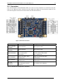
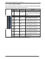
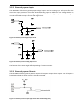
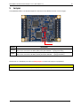
3.2 Connectors The controller/driver board MCST3601 offers two rows of screw connectors at each end of the pcb. There is one additional motor connector and two single row headers for step direction output for axis one and two (please note that the internal driver axis has the number 0). S/D 1
SD/2
Connector Connector
1
4
4
1
1
1
12
12
1
4
Motor
Connector
USB
Connector
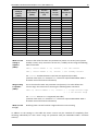
Figure 3.2 Overview connectors Label Motor / Encoder connector Power / Interface connector Motor connector S/D 2 connector S/D 3 connector Mini‐USB Connector Connector type Mating connector type Screw connector Wire: up‐to 0.5 mm2 Screw connector Wire: up‐to 0.5 mm2 Molex PicoBlade, 4pin, 1.25mm pitch 53047‐0410 Single row header, 4pins, 2.54mm pitch Connector housing: Molex 51021‐0400 Contacts: Molex 50079‐8000 Wire: AWG 26‐28 Single row header, 4pins, 2.54mm pitch Molex 500075‐1517 Mini USB Type B vertical receptacle Table 3.1 Connectors and mating wires / connectors Single row female plug, 4pins 2.54mm pitch Single row female plug, 4pins 2.54mm pitch Any standard mini‐USB plug