1
6
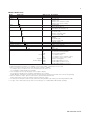
Features of FLEXA
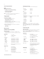
Sensor Calculation
For pH + pH
For DO + DO
Differential
Average
Sensor Calculation
For SC + SC*
Ratio
Average
Differential
Passage[%]
Rejection[%]
Deviation[%]
pH calc.
Software
(input1) - (input2)
(input1 + input2) / 2
(input1) / (input2)
(input1 + input2) / 2
(input1) - (input2)
(input2) / (input1) X 100
(input1 - input2) / (input1) X 100
(input2 – input1) / (input1) X 100
(VGB) pH=8.6+log{(input1) - (input2)/3}
Note: for resistivity, only differential and average can be selected.
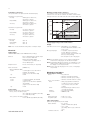
PROFIBUS-PA Communications (Pending)
Input signal
: Digital
Supply voltage
: 9 to 32 V DC
Operating current
: 26.0 mA (pH) and 24.5 mA SC, ISC,
and DO
Operating values
: According to IEC 1158-2
Bus connection
: Fieldbus interface based on IEC
1158-2 according to FISCO-Model
Power supply
: Power supply is achieved dependant
on the application by means of
segment coupler
Data transfer
: According to PROFIBUS- PA profile
class B based on EN 50170 andDisplay
DIN
19245 part 4
GSD file
: The actual file can be downloaded
Sensor 1
from www.profibus.com
Configuration
: Local with 6 keys
Software
: Firmware based on Siemens DPC31
stack.
Hardware
: PC- or PCMCIA-interfaces from
Siemens
Sensor 2
R(1)
Display
Other control
: Siemens PDM systems
Electrical connection : Terminals acc. to IEC 1158-2
Alive
Fieldbus-cable-types : Twisted and shielded
two wire cable
Sensor 1
according to recommendation based
mA
on IEC 1158-2
Cable diameter
: 6 to 12 mm (0.24 to 0.47 inch)
Alive
Sensor 2
:N
ational Instruments, NI-FBUS
configurator
Hardware
: FBUS-interfaces from National
Instruments (AT-FBUS and PCMCIA
FBUS)
Other control systems : Yokogawa PRM, DMT
Redundancy
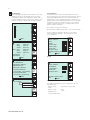
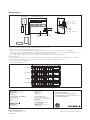
A Variety of calculated data from two measuring parameters
is selectable for each measurement. The redundant system is
a function of backing up the 1st module with the 2nd module.
This function is designed such that under normal conditions, the
sensor-1 pH value is the current output and if the sensor 1 fails,
the sensor-2 pH value is the current output.
Time
Sensor 1 operative
Sensor 1 Fails
Sensor 1
Alive
mA output
Sensor 2
Alive
Fail
Alive
Repair sensor 1
Alive
mA output
Automatically switch
to sensor 2
Switch back to sensor 1
manually
Alive
Alive
mA output
Example 1: sensor failure
Time
Sensor 1
Alive
mA output
Sensor 2
R(1)
Alive
Sensor 1 in calibration
R(1)
Display
End
Start
Calibration
Alive
Sensor 1
Sensor 1 operative
R(2)
Alive
mA output Dead
back to sensor 1
Intentionally switch
mA Switch
manually
to sensor 2
Alive
mA output
R(2)
Alive
Sensor 2
Example
Alive 2: sensor calibration
Dead
Repair sensor
Dead
Alive
Alive
Repair sensor Alive
Dead
mA
Alive
mA 1 fails, the output is automatically
If sensor
switched to the
Sensor 1 is dead.
sensor-2 value.
(automatic)
redundant restart (ma
Even if a failure on the sensor 1 is recovered automatically
Alive
Alive
after failure detection, the output will not be switched back
R(2)
R(1)
automatically and the
sensor 2 value mA
will continue to be output.
Repair sensor
Dead
Alive
After Dead
repairing sensor 1,
Output setup
Res
Sensor 1 is dead.
redundant system
Alive
reset the backup made
mA Output mA
Return m
(automatic)
restart (manual)
by the
redundant system.
This enables the sensor 1
value to be incorporated
Alive
Alive
in the output.On the
mAsystem,
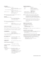
FOUNDATION Fieldbus H1 Communications (Pending)
Reset redundant
Configure Hold
Input signal
: Digital
selection of “Yes” makes
Sensor 1 is dead.
redundant system
Reset redundant
Yes
Supply voltage
: 9 to 32 V DC
the output return to the
(automatic)
restart (manual)
No
Operating current
: 26.0 mA (pH) and 24.5 mA SC, ISC,
output ofOutput setup
the 1st module.
Reset redundant syst
and DO
mA Output
Return mA to Sensor1?
Operating values
: According to IEC 1158-2
This display is the
Bus connection
: Fieldbus interface based on IEC
example when
1158-2 according to FISCO-Model
“Redundant” is selected
Power supply
: Power supply is achieved dependant
as a process parameter.
Output setup
Reset redundant system
on the application by means of
mA Output
Return mA to Sensor1?
segment coupler
Data transfer
: FF Specification Rev. 1.4, Basic
Configure Hold
device
Reset redundant
Yes
Function blocks
: 3xAI, Transducer, Resource
No
Files
: Actual file can be downloaded from
our homepage
Configure Hold
Configuration
: Local with 6 keys,
Reset redundant
Yes
Example 2: Calibration No
GS 12A01A02-01E-E