1
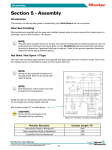
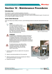
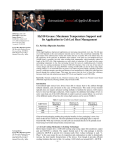
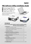
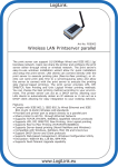
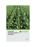
Valve Actuators
®
Section 10 - Hydraulic / Pneumatic
Actuators
Introduction
This section explains how to assemble and install the valve actuator for:
• 5500 Series
• 6500, 6600, and 6700 Series
• 7100 Series
Installation and Assembly of the Valve Actuator
The following procedure explains how to assemble and install the valve actuator on a bench.
NOTE
These procedures require certain parts to be lubricated or greased.
1
1. Screw
2
2
2
5
5
4
3
4
5
3
6
7. O-Ring
9
12
8. Circlip
10
13
9. HY6X00 Spring Assembly
14
10. HY6X00 Stud
15
11. HY7100 Spacer
7
13
13
14
15
8
8
8
16
16
12. Outer Seal
13. Piston
14. Inner Viton O-Ring
16
17
4. Cylinder Top O-Rings
6. Piston Top
11
12
3. Locating Dowel
5. Small O-Ring
7
7
8
2. Cylinder Top
4
6
3
6
Valve Actuator Components
1
1
17
17
15. Outer Viton O-Ring
16. Rod Seal
18
18
18
19
19
5500 Series
6X00 Series
19
7100 Series
Hot Runner User Manual
Not under documentation control if printed. May be revised without notice. Electronic version is available at www.moldmasters.com
10-1
17. Cylinder
18. Cylinder Bottom O-Rings
19. Valve Pin
Figure 10-1
Revision 14
©06-2011
Valve Actuators
®
Pre-Installation
1. Prior to installing the actuator unit, check that all fluid lines in the mold plate are de-burred and do not have
any metal chips.
2. Remove all rust inhibitor from the exterior of each part, prior to installation.
3. Use denatured alcohol to remove the rust inhibitor compound from each part. Do not clean the interior of the
cylinder.
Cylinder Bottom Assembly
1
1. Insert the rod seal support disk into the cylinder (6X00 and 7100 only).
2. Press the rod seal into position.
2
3. Install the circlip with sharp edges facing up.
4. Lubricate the bottom cylinder external O-rings and install.
Figure 10-2 6X00 and 7100
Bottom Cylinder
1. Circlip 2. Rod Seal
1
2
3
Figure 10-4 Seal Kit PS0003
1. Back Up Ring 2. Inner Viton O-Ring 3. Outer Seal
Figure 10-3 6X00 and 7100
Bottom Cylinder O-Rings
Piston Assembly
5500 Only
1. Lightly use silicone grease and install the O-ring on the
piston.
Figure 10-5 Piston
Assembly
1. Back Up Ring 2. Inner
Viton O-Ring 3. Stud
2
1
3
6X00 and 7100 Series
1. Using silicone grease, lightly grease and install the inner
Viton O-ring on the piston.
2. Install the back-up ring.
3. Install the outer seal. The seal should sit on top of
the inner Viton O-ring. An installation tool is available
(PS0003TOOL02) for installing the seal.
4. Once all 3 rings have been assembled, place installation
tool PS0003TOOL01 over assembly as shown and allow
rings to settle.
Figure 10-6 Piston
Assembly
1. Outer Seal 2. Installation Tool 3. Stud
2
1
3
Figure 10-7 Piston
Assembly
1. Stud 2. Installation Tool
PS0003TOOL02
1
2
Hot Runner User Manual
Not under documentation control if printed. May be revised without notice. Electronic version is available at www.moldmasters.com
10-2
Revision 14
©06-2011
Valve Actuators
®
Cylinder Top Assembly
4
On the inside face of the cylinder top:
1. Insert the locating dowel.
3
2. Using silicone grease, lightly grease and insert the small O-ring.
3. Using silicone grease, lightly grease and insert the large O-ring.
1
2
Figure 10-8 Typical Cylinder Top
1. Large O-Ring 2. Small O-Ring
3. Cylinder Top 4. Locating Dowel
Valve Pin Finishing of Tip
5500 Series
1. Install the cylinder (where applicable) and piston bottom, (without the
pin and piston top) into the hydraulic plate.
2. Measure the distance AD and AC.
NOTE
Heat expansion difference to be removed from pin head.
3. Cut pin to calculated length “L”. (L = AD - AC + DE + 3.05*+0.02**)
L = overall length from tip to top of pin head
* 3.05 = head of pin
** 0.02 = pressure preload
4. Grind the valve pin tip an angle of 20° per side (40° inclusive).
5. Lap the tip of the pin into the land area (steel section in the gate area).
Refer to Figure 10-10 using a lapping guide bushing or valve bushing
as a lapping guide. Recommended lapping paste 400 - 600 grit.
Figure 10-9 Measure Distance
1
40°
2
3
Figure 10-10a 1. Nozzle Flange
Bore 2. Machined Bushing for
Center Alignment
3. Tapered/Angled Valve Pin 4.
Nozzle Well Bore 5. Cavity
1
1
4
5
2
Figure 10-10b Land Location
1. Land Area 2. Cavity Face
Hot Runner User Manual
Not under documentation control if printed. May be revised without notice. Electronic version is available at www.moldmasters.com
10-3
Revision 14
©06-2011
Valve Actuators
®
6X00 Series
1. Calculate the heat expansion factor.
Fh = (Processing temperature - Mold temperature) °C x 0.000012.
2. Calculate the heat expansion of the valve pin.
HE = distance BC x heat expansion factor = BC x Fh
3. Cut pin to calculated length “L”. (L = AC - 36.35 - HE + 0.3 + CD).
4. Grind the valve pin tip to an angle of 20° per side (40° inclusive).
Refer to Figure 10-7.
5. Lap the tip of the pin into the land area (steel section in the gate
area) using a lapping guide bushing or valve-bushing as a lapping
guide. Recommended lapping paste 400 - 600 grit.
6X00 Series
7100 Series
Figure 10-11 Measure Distance
1. Install the cylinder (where applicable) and piston bottom, (without
the pin and piston top) into the hydraulic plate.
2. Measure the distance AC and BC.
3. Calculate the heat expansion factor.
Fh = (Processing temperature - Mold temperature) °C x 0.000012.
4. Calculate the heat expansion of the valve pin.
HE = distance BC x heat expansion factor = BC x Fh
5. Cut pin to calculated length “L”. (L = AC - 36.35 - HE + CD)
6. Grind the valve pin tip to fit the cylindrical gate. (Refer to the system gate detail.)
7. Assemble the hydraulic unit.
8. Heat the hot runner system to processing temperature.
9. Soak the pin in the hot runner system for 10 minutes to achieve
the maximum heat expansion of the pin at the processing temperature. (Mold cooling should be running).
7100 Series
Figure 10-12 Measure Distance
10. Measure the distance CD in the heated condition. Check that the
head of the pin is seated.
11. Calculate the dimension to be ground (L2). L2 = CD (measurement) - CD (specified).
12. Grind the pin end to remove L2 (finish cut).
NOTE
W
hen the gate vestige is critical, it is recommended to
mold sample parts and measure samples to adjust the
final pin length.
Hot Runner User Manual
Not under documentation control if printed. May be revised without notice. Electronic version is available at www.moldmasters.com
10-4
Revision 14
©06-2011
Valve Actuators
®
Steel quality in the gating area must have:
•
•
•
•
High grade of toughness (H13, 1.2344)
Hardness of HRc, 46-48
No nitration
No chrome plating
The bottom of the nozzle well in the gate area must be free of stress caused by:
• Rough EDM
• Rough machining
• Sharp corners (JIG grinding is recommended)
Valve Pin Lapping Procedure for Tapered Valve Pins
5500 and 6X00 Series
If the shut off between the valve pin and gate area is not satisfactory, lapping of the valve pin into the gate will be
required. A support bushing that fits into the nozzle flange area should be manufactured with the pin diameter in
the center of the support bushing to properly align the pin with the gate area (see below). Or use the nozzle well
diameter of the cavity for the support bushing as a lapping guide.
1. Install the machined bushing with the center hole matching the pin diameter.
1
2. Insert the valve pin through the bushing.
3. Add 400 grit lapping paste to the tapered area of the pin and lapp into the
gate. Verify the shut-off with bluing compound.
2
4. Be sure to remove all lapping paste from the valve pin and cavity, before
continuing with actuator assembly.
3
4
Figure 10-13 Bushing for Pin Lapping
1. Nozzle Flange Bore 2. Machined Bushing for Center Alignment
3. Tapered/Angled Valve Pin 4. Nozzle Well Bore 5. Cavity
5
NOTE
Do not permit the lapping paste to enter the valve bushing bore.
WARNING
A
void skin contact with decomposing O-rings. Use appropriate protective clothing. Failure to do so
can cause serious injury.
NOTE
The Viton O-rings used for the valve actuators are rated for operation below 200°C (400°F).
Always turn ON the plate cooling prior to heating the hot runner system. Refer to the warning if Orings have been subjected to higher than rated temperatures.
Hot Runner User Manual
Not under documentation control if printed. May be revised without notice. Electronic version is available at www.moldmasters.com
10-5
Revision 14
©06-2011
Valve Actuators
®
Valve Pin Finishing of Head
5500 Series
1. Heat the hot runner system to the processing temperature.
2. Allow the pin to soak in the hot runner system for 10 minutes to achieve the
maximum heat expansion of the pin at processing temperature. (Mold cooling must be running).
WARNING
E
xtreme heat. Avoid contact with heated surfaces.
U
se appropriate protective clothing. Failure to do so can cause serious injury.
3. Measure the distance AB in heated condition.
NOTE
Heat expansion difference to be removed from pin head.
4. Check that the tip of the pin is fitted correctly into the land.
5. The heat expansion difference between the mold and hot runner is removed
by grinding the back of the pinhead.
6. HED = AC - (AB + 3.05 + 0.02 preload)
HED = heat expansion difference
* 3.05 = head of pin
** 0.02 = pressure preload
Figure 10-14 Measure Distance
7. Continue to re-assemble the actuator assembly. The maximum pin preload
in the land under full heat expansion must not exceed 0.02mm.
NOTE
The standard stroke of the HY550* A/E is 4.0mm. This can be increased to maximum of 8.0mm by removing material from the piston
top.
The stroke of the HY550* C/F is 8.0mm and cannot be altered.
Valve Pin Assembly
5500 Series
1. Check the valve pin length. Refer to:
"Valve Pin Finishing of Tip",
"Valve Pin Finishing of Head".
2. Slide the valve pin into the piston.
3. Grease and install the O-ring.
4. Install the piston top and tighten, torque setting 15-20 ft -Ibs (20-27 Nm).
Hot Runner User Manual
Not under documentation control if printed. May be revised without notice. Electronic version is available at www.moldmasters.com
10-6
Revision 14
©06-2011
Valve Actuators
®
6X00 Series
1. Check the valve pin length. Refer to Valve Pin Finishing of Tip.
2. Slide the valve pin into position.
CAUTION
Failure to install the disk springs in the correct order will cause damage to the gate.
1
3. Assemble the disk springs to the spring retainer stud.
a. Check for the correct orientation of the disk springs when
installing.
b. HY6500 series: Align the springs in 5 alternating groups of 5,
convex and concave.
c. H
Y6600 and 6700 series: Align the springs in 8 alternating
groups of 6, convex and concave.
4
3
2
4. Install the disk spring assembly on top of the valve pin.
5. Grease and install the O-ring.
6. Install piston top and tighten, recommended torque setting 15-20 ftIbs (20-27 Nm).
Figure 10-15 8 X 5 Disk Spring
Assembly
1. Cylinder Top 2. Valve Pin
3. Spring Retainer Stud 4. Disk
Springs
7100 Series
1. Check the valve pin length.
2. Slide the valve pin into the piston.
3. Install the actuator spacer with the threaded side facing towards the
piston top.
NOTE
he threaded side is used for removal or installation use. By installing a screw into the spacer’s
T
threaded end it allows for simple extraction of the spacer.
4. Grease and install the O-ring.
5. Install piston top and tighten, recommended torque setting 15-20 ft-Ibs. (20-27 Nm).
5
1
1
2
4
3
Figure 10-16 Piston Spacer Installation
1. Threaded Side 2. O-Ring
3. Spacer Installed (Threads Up)
4. Piston 5. Piston Top
4
Hot Runner User Manual
Not under documentation control if printed. May be revised without notice. Electronic version is available at www.moldmasters.com
10-7
Revision 14
©06-2011
Valve Actuators
®
Installing the Valve Actuator to the Hydraulic Plate
The following procedure is for new systems.
1. Lubricate the sides of the actuator cylinder, before installing into the
hydraulic plate.
CAUTION
C
heck for sharp edges before installing the cylinder. Failure
to do so could damage O-rings.
2. Tap the cylinder into the bore of the actuator plate with a nylon mallet. 3. Position the piston installation tool (PS0003TOOL01) on top of the
Figure 10-17 Cylinder Installation
cylinder.
4. Install the valve pin and piston into the cylinder bottom.
5. Press the valve pin into position, using a nylon mallet to finish seating the valve pin into the assembly.
CAUTION
H
eat sensitive materials should be purged with a compatible
less sensitive material.
If the system is not purged material in the manifold could
degrade resulting in poor quality of product.
6. Remove the installation tool.
7. Check that the cylinder top dowel and O-rings are installed.
8. Install the cylinder top.
Figure 10-18 Valve Pin and Piston
Installation
1. Valve Pin and Piston 2. Installation
Tool
Figure 10-19 Cylinder Top
1. Cylinder Top 2. Mounting Screws
3. Hydraulic Plate
Hot Runner User Manual
Not under documentation control if printed. May be revised without notice. Electronic version is available at www.moldmasters.com
10-8
Revision 14
©06-2011
Valve Actuators
®
Maintenance Procedure
HY5500, HY6X00 and HY7100 Series
Actuator units should be inspected every 12 months or per pre-determined maintenance schedule.
The following procedure is performed on a bench.
For Oil Systems:
1. Remove oil from system.
2. Remove the cylinder top with tool in upright position to prevent oil
from entering the system.
3. Heat up the system (required to remove the valve pin).
For Pneumatic Systems:
1. Remove the cylinder top for every zone.
2. Heat up the system (required to remove the valve pin).
Figure 10-20 HY5500 Series
Cylinder Extraction Tool Kit
WARNING
E
xtreme Heat. Avoid contact with heated surfaces. Use
appropriate protective clothing. Failure to do so can cause
serious injury. If possible keep cooling on within hot half.
Do not assemble new O-rings if the plates are still hot.
Drain the oil before removing the pin from the hydraulics.
3. Install the cylinder extraction tool to assist with the removal of the
cylinder.
4.
5.
6.
7.
Disassemble the system.
Inspect components.
Figure 10-21 HY6/7*00 Series
Cylinder Extraction Tool Kit
Replace O-rings.
O-ring replacement kit is OR550P1 for 5500 series and OR650P2 for
6X00 and 7100 series.
8. When installing the rod seal, check that the rod seal is seated to the
base of the cylinder and is secured in place with the circlip.
9. To complete the assembly, refer to:
a.
b.
c.
d.
e.
Cylinder Bottom Assembly
Piston Assembly
Cylinder Top Assembly
Figure Valve Pin Assembly
Installing the Valve Actuator to the Hydraulic Plate.
Figure 10-22
Valve Disk Extraction Tool
Hot Runner User Manual
Not under documentation control if printed. May be revised without notice. Electronic version is available at www.moldmasters.com
10-9
Revision 14
©06-2011
Hot Runner User Manual
Not under documentation control if printed. May be revised without notice. Electronic version is available at www.moldmasters.com
10-10
•
•
KEY04
EXTSTUDM8
CYLINDER
EXTRACTION TOOLS
•
EXTOOL06
PISTON
EXTRACTION TOOLS
(HY5500 A/B/E)
EXTOOL5500P
• EXTOOL06
• KEY04
• EXTSTUDM8
HY5500X
•
•
EXTOOL04
(Piston Top
Removal)
PS0001TOOL01
(Piston Assembly)
CYLINDER
EXTRACTION TOOLS
•
EXTSTUDM6
(Piston)
PISTON
EXTRACTION TOOLS
EXTOOL2300P
• EXTOOL04
• PS0001TOOL01
• EXTSTUDM6
PN2300X
EXTOOLAS01
Common Extraction
Tool Assembly
•
•
PS0003TOOL01
(Piston Assembly)
PS0003TOOL02
(Seal Assembly)
INSTALLATION
TOOLS
•
•
•
EXTOOL01
(Piston Top
Removal)
KEY05
EXTSTUDM8
CYLINDER
EXTRACTION TOOLS
EXTOOL6500P
• EXTOOL01
• EXTOOL05
• PS0003TOOL01
• PS0003TOOL02
• KEY05
• EXTSTUDM8
HY6*00X
HY7*00X
•
EXTOOL05
(Piston)
PISTON
EXTRACTION TOOLS
®
Valve Actuators
Extraction Tool Assembly
Revision 14
©06-2011