1
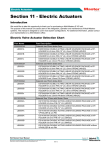
®
Specialty Systems - Melt-Disk
Section 15 - Melt-Disk System
Introduction
We would like to take this opportunity to thank you for purchasing a Mold-Masters Melt-Disk system.
The purpose of this manual is to assist users in the integration, operation and maintenance of Mold-Masters systems. This manual is designed to cover most system configurations. For additional information,
please contact your representative or a Mold-Masters office.
Safety
Please see Section 3 for important safety information.
The responsibility for the safety of personnel remains exclusively with the employer. It is the obligation
of the employer to properly train and instruct its personnel in the safe operation of equipment including
maintenance and the purpose and proper use of all the safety devices. In addition, the employer must
provide its personnel with all necessary protective clothing, including such items as a face shield and heat
resistant gloves. Any instructional material provided by Mold-Masters for the operation and maintenance
of equipment, does not in any way absolve the employer from fulfilling these obligations and Mold-Masters disclaims liability for injury to personnel using equipment supplied.
Notices
Notices throughout this manual indicate additional information that must be performed or observed.
WARNING:
Safety warning indicates a potentially hazardous situation, which if not avoided, could
result in serious injury or death.
CAUTION:
Caution indicates that damage to equipment is possible.
NOTE:
Important indicates useful additional information or is used as a reminder for important
information.
Hot Runner User Manual
Revision 12
Not under documentation control if printed. May be revised without notice Electronic version is available at www.moldmasters.com
©05-2010
15-1
®
Specialty Systems - Melt-Disk
System with cast in heater element
Insulation Board
Leader Pins
Locating Ring
Top Clamp Plate
Jiffy Plugs
Pressure Disk
Center Heater
Manifold
Nozzle
Electrical Box
Leader Bushing
Wire
Retainer
Manifold Plate
Name Plate
Melt
Disk
Melt Transfer
Link
Transfer Seal
Torpedo Tip
Melt-Disk
Locator
Hot Runner User Manual
Revision 12
Not under documentation control if printed. May be revised without notice Electronic version is available at www.moldmasters.com
©05-2010
15-2
®
Specialty Systems - Melt-Disk
Hot-Half Pre-Assembly - Melt-Disk Preparation / Cleaning
All nozzles, manifolds and components must be free of the rust inhibitor applied at the factory.
1. Disassemble the Melt-Disk assembly.
2. Wipe down Melt-Disk.
3. Remove the part and wipe clean. If necessary, use a cotton swab to clean narrow interior surfaces or
screw threads. For larger surfaces, such as mold plates use thinner in spray form to clean channels and
recesses.
Figure 15-1 Cleaning Parts
4. Anti-seize the threads of the Gate Seals, using Mold-Masters supplied compound.
Figure 15-2 Anti-Seize Compound Application
Hot Runner User Manual
Revision 12
Not under documentation control if printed. May be revised without notice Electronic version is available at www.moldmasters.com
©05-2010
15-3
®
Specialty Systems - Melt-Disk
5. Insert the pointed end of the tips (torpedoes) into the threaded end of the Gate Seal.
Figure 15-3 Assembling Gate Seal
6. Thread the Gate Seal Assembly into the Melt-Disk. Secure the Melt-Disk in a soft vice and torque Gate
Seals in the cold condition to value specified below or in the General Assembly Drawings. Do not over
tighten vice. Ensure none of the components are damaged.
Thread size
Imperial
Metric
M9
10 - 11 ft lbs
14- 15 Nm
7. Torque Gate Seals in heated condition at processing temperature as specified in the General Assembly
Drawings.
CAUTION
Failure to torque the gate seals at processing temperatures may result in leakage.
Figure 15-4 Torquing Gate Seals
Hot Runner User Manual
Revision 12
Not under documentation control if printed. May be revised without notice Electronic version is available at www.moldmasters.com
©05-2010
15-4
®
Specialty Systems - Melt-Disk
Nozzle Thermocouple Assembly
1. Although not necessary, a thermal compound may be applied to the tip of the thermocouple.
2. Connect the thermocouple as specified in the General Assembly diagram. See also Assembly
Section 5.
Melt-Disk Thermocouple Assembly
1. Remove the thermocouple retaining screw from
the Melt-Disk.
Figure 15-5
2. Insert the thermocouple tip into the thermocouple
hole. Thermocouple must bottom in hole.
Figure 15-6
3. Bend the thermocouple back 90°.
Figure 15-7
Hot Runner User Manual
Revision 12
Not under documentation control if printed. May be revised without notice Electronic version is available at www.moldmasters.com
©05-2010
15-5
®
Specialty Systems - Melt-Disk
4. Secure the thermocouple with the screw from
#1.
Figure 15-8
5. Use heat resistant tape to secure the nozzle
wires and thermocouple wires just above the
insulator pod.
Figure 15-9
6. Prepare all remaining Melt-Disks the same way
and set aside.
Figure 15-10
Hot Runner User Manual
Revision 12
Not under documentation control if printed. May be revised without notice Electronic version is available at www.moldmasters.com
©05-2010
15-6
®
Specialty Systems - Melt-Disk
Assembly of Melt-Link to Nozzle
1. Anti-seize the threads of the Melt-Link, using
Mold-Masters supplied compound.
Figure 15-11
2. Thread the Melt-Link into the nozzle.
3. Torque Melt-Link COLD to value specified in the
General Assembly Diagram.
Figure 15-12
Hot Runner User Manual
Revision 12
Not under documentation control if printed. May be revised without notice Electronic version is available at www.moldmasters.com
©05-2010
15-7
®
Specialty Systems - Melt-Disk
Manifold Cavity Preparation
1. Calculate the following dimensions at ambient (room) temperature:
a. M
easure the depth of the nozzle bore “a” from the top of the Manifold Plate to the Nozzle Support Base.
a
Figure 5-13 Calculating Nozzle Bore Depth "a"
b. Measure the top section of the nozzle flange “b”.
b
Figure 5-14 Calculating Nozzle Flange Height "b"
c. Measure the Manifold thickness “c”.
c
Figure 5-15 Calculating Manifold Thickness "c"
Hot Runner User Manual
Revision 12
Not under documentation control if printed. May be revised without notice Electronic version is available at www.moldmasters.com
©05-2010
15-8
®
Specialty Systems - Melt-Disk
Manifold Cavity Preparation - Con't.
2. Calculate Pressure Disk height “d” = a – b – c – air gap.
This is the value (“d”) that’s required for correct assembly. Refer to the General Assembly Drawing
for reference values, such as the air gap.
3. T
he actual height (thickness) of the supplied Pressure Disk “e” will be of a value that’s higher than the
value “d”. Calculate the difference, and then divide by 2. This is the value that will need to be ground
from each side of the Pressure Disk.
Pressure Disk Details
1. Install the manifold to the nozzle.
2. Refer to the general assembly drawing for pressure disk dimensions before calculating the pressure valve disk height.
3. Pressure disks are supplied oversize in height,
grind equal amounts from each side to cold
clearance and retain maximum strength of the
'V' form. Some systems require a larger air gap.
Refer to the General Assembly drawing.
4. Remove the sharp corners after grinding and
clean the disk well to ensure no grinding dust
remains on the disk.
Stone
Sharp
Corners
Grind
Equal
Amounts
Figure 5-16 Pressure Disk Details
5. Install the pressure disk spring dowel to the
manifold.
6. Install the pressure disk to the manifold.
Example Calculations
Nozzle Bore Depth “a”:
Nozzle Flange Height “b”:
Manifold Thickness “c”:
Air Gap as noted on drawing:
91.39 mm
43.16 mm
43.16 mm
00.05 mm
Pressure Disk Height “d”:
91.39 – 43.16 – 43.16 – 0.05 = 5.02 mm
Supplied Pressure Disk “e”:
5.10 mm
Difference between supplied Pressure Disk “e” and required Pressure Disk “d”: 5.10 mm – 5.02 mm = 0.08
mm
Material to be removed from each side of the Pressure Disk: 0.08mm ÷ 2 = 0.04 mm
Nozzle bores and pressure disks must be within tolerances specified in the General Assembly drawing.
Hot Runner User Manual
Revision 12
Not under documentation control if printed. May be revised without notice Electronic version is available at www.moldmasters.com
©05-2010
15-9
®
Specialty Systems - Melt-Disk
Final Assembly of the Manifold Plate
1. Insert each prepped nozzle into the nozzle cavities. Make sure the wires are not bent or pinched anywhere. Place a zone number on each wire and thermocouple. Group and tape wires for each zone and
plug. Feed all wires through the wire channels towards the electrical box channel.
NOTE:
Check GA drawing for information for your system.
2. For some systems locators are supplied oversize
(X) and must be ground to the same level as the
top of the nozzles. Remove the material from the
bottom face of the locator (FACE Y). This will allow
SURFACE (A) and SURFACE (B) to be at the same
level in the cold condition.
For other systems there is a long distance between
the manifold locator and the nozzles and the manifold locator needs to be higher than the nozzles
(approximately 0.03 mm). Before grinding the
manifold locator it is strongly advised to check the
GA drawing.
SURFACE A
SURFACE B
FACE Y
Figure 5-17 Locator Surface
Figure 5-18 Nozzle Insertion
3. Feed the wires back through the wire channel in the mold base to the Mold Plug. Do not cut the wires
until the remaining components are installed.
Figure 5-19 Manifold Locator Adjustment
Hot Runner User Manual
Revision 12
Not under documentation control if printed. May be revised without notice Electronic version is available at www.moldmasters.com
©05-2010
15-10
®
Specialty Systems - Melt-Disk
Electrical Box Preparation
1. Use washers to offset the electrical box from manifold plate. This prevents the top plate from bumping
into the electrical box during assembly. Feed all wires through as shown. Trim the wires back, noting
the number tags assigned to each wire. Do not cut these tags off.
Figure 5-20 Electrical Box Mounting Detail
Final Mold Plate Assembly
1. Using appropriate tools, place the Manifold into the Manifold Cavity of the Manifold Plate, as shown
below. Ensure that no electrical or thermocouple wires are pinched, frayed or bent. Backplate and
heater assembly shown already assembled. (Normally assembled at a later step).
2. Secure wires to the Manifold Plate using wire retainers.
Figure 5-21 Inserting Manifold into Manifold Plate
WARNING!
Make sure the lifting eyebolt, chain and crane can support the weight of the manifold.
Failure to do so may cause serious injury.
Hot Runner User Manual
Revision 12
Not under documentation control if printed. May be revised without notice Electronic version is available at www.moldmasters.com
©05-2010
15-11
®
Specialty Systems - Melt-Disk
Final Mold Plate Assembly - Con't.
3. If required, attach a crane of sufficient lifting capacity to the manifold.
4. Place the manifold on top of the nozzles and locator.
5. Place Pressure Disks (machined to proper thickness as detailed in section Manifold Cavity Preparation)
atop the Manifold.
6. Connect Ground Wire and Manifold Thermocouple.
Figure 5-22 Manifold Preparation
System Screw Torques
Quality and length of screws must be as specified on Mold-Masters general assembly drawings.
Torque Chart for System Assembly Screws
Metric
Torque Setting
Imperial
Torque Setting
M5
7 Nm
#10-32
5 ft lbs
M6
14 Nm
1/4-20
10 ft lbs
M8
20 Nm
5/16-18
15 ft lbs
M10
40 Nm
3/8-16
30 ft lbs
M12
60 Nm
1/2-13
45 ft lbs
M16
145 Nm
5/8-11
107 ft lbs
M20
285 Nm
3/4-10
210 ft lbs
Exception: Bridge manifold mounting screws should be torqued 1/3 higher than specified on GA drawings.
Hot Runner User Manual
Revision 12
Not under documentation control if printed. May be revised without notice Electronic version is available at www.moldmasters.com
©05-2010
15-12
®
Specialty Systems - Melt-Disk
Installing the Manifold Thermocouple
1. Although not necessary, a thermal compound may be applied to the thermocouple tip to ensure a good
contact.
2. Insert the thermocouple into the bore. Check that the thermocouple is touching the bottom of the hole.
3. Press down on the thermocouple and gently bend the thermocouple sheath 90°.
4. Check that the thermocouple sits in the manifold cutout.
5. Install the thermocouple washer and screw.
6. Install a zone number on each wire and thermocouple.
7. Organize and tape together wires for each zone and plug.
8. Feed the wires back through the wire channel in the mold base to the electrical box and secure with
wire retainers.
1
4
90°
2
3
Figure 5-23 Thermocouple Installation
1. Thermocouple 2. Screw 3. Washer 4. Assembly
Manifold Center Heater (Optional)
1. Attach Back Plate to Manifold Plate as follows:
a. Snug up each fastener but do not tighten.
b. Once all fasteners are snug, torque each to 20 ft. lbs.
2. Place the Center Heater over the Back Plate. Attach the Cover plate and torque to 20 ft. lbs. Run the
wires through the appropriate channel into the Electrical Box.
Figure 5-24 Heater and Back Plate Assembly
Hot Runner User Manual
Revision 12
Not under documentation control if printed. May be revised without notice Electronic version is available at www.moldmasters.com
©05-2010
15-13
®
Specialty Systems - Melt-Disk
Final Assembly
1. Rub a small amount of High Temperature Grease on the Clamp Plate guide pins, and lower onto Manifold plate. Ensure no wires will be pinched.
WARNING!
Make sure the lifting eyebolt, chain and crane can support the weight of the Clamp Plate.
Failure to do so may cause serious injury.
2. Dab anti-seize compound on tip of the fasteners. Tighten from the center of the plate out towards the
edges.
Figure 5-25 Securing the Clamp Plate
Hot Runner User Manual
Revision 12
Not under documentation control if printed. May be revised without notice Electronic version is available at www.moldmasters.com
©05-2010
15-14
®
Specialty Systems - Melt-Disk
3. Torque each fastener to value specified for Plate Assembly Screw on the General Assembly Drawings.
Attach the locating ring and tighten.
Figure 5-26 Securing the Cover Plate
4. Flip assembled hot half over. Use appropriate sized wooden blocks to rest hot half to prevent damage
to nozzles and other components.
WARNING
Make sure the lifting eyebolt, chain and crane can support the weight of the manifold. Failure to do so may cause serious injury.
5. Attach connector pins ends to each wire and crimp. Configure electrical connector as specified in engineering print.
Figure 5-27 Electrical Connector Assembly
Assemble Melt-Disk to Nozzle
1. Assemble Melt-Disks onto the
nozzles according to mold design.
2. Ensure the sharp edge of the
melt link does not get
damaged.
Figure 5-28
Hot Runner User Manual
Revision 12
Not under documentation control if printed. May be revised without notice Electronic version is available at www.moldmasters.com
©05-2010
15-15
®
Specialty Systems - Melt-Disk
Melt-Disk System Start Up & Shut Down
Also refer to Section 8 System Start Up & Shut Down and the MZ TempMaster-Series Controller manual.
Start Up
NOTE:
When running thermally sensitive materials, use a thermally stable material as recomended by the material supplier for the initial start-up.
1. Turn ON the machine barrel and mold cooling system.
2. Prior to start-up, ensure the:
• Machine barrel is up to processing temperature.
• Mold cooling is on and at cooling temperature.
3. Heat Manifold zones & Inlet to processing temperature.
4. Heat Melt-Disks to processing temperature.
5. Heat Nozzles to processing temperature. A small amount of material may weep at this stage.
6. Allow to heat soak at least 10 minutes.
7. Fill system under low pressure extrude (using screw rotation).
8. Set Melt-Disk temperature at least 10°F lower than nozzles.
NOTE:
For hot runner systems using heater plates, allow 10 minutes of soak time after the
systemreaches processing temperature.
CAUTION:
WARNING:
Failure to follow the above procedure may result in leakage/damage occurring in the hot
runner.
When the mold is open never inject material through hot runner system under high pressure. Failure to do so can result in serious injury or death.
Shut Down
NOTE:
For horizontal tips, refer to the MZ Controller, operating manual.
1. Maximize decompression stroke prior to shut down. This will minimize drool at start up when there is
limited gate cooling.
2. Reduce Nozzle temperatures to 300°F (150°C).
3. Reduce Melt-Disk temperatures to 300°F (150°C).
4. Turn off all zones.
NOTE: Thermally sensitive materials should be purged from the hot runner system prior to shut
down using a thermally stable material with a similar processing temperature. For example, a system running PVC should be initially started and subsequently shut down on LDPE.
Hot Runner User Manual
Revision 12
Not under documentation control if printed. May be revised without notice Electronic version is available at www.moldmasters.com
©05-2010
15-16
®
Specialty Systems - Melt-Disk
Disassembly for Maintenance
NOTE:
Before shutting down the molding machine and mold, use maximum screw decompression to
remove as much molten plastic from the hot runner system as possible.
1. Disassemble mold to expose the Melt-Disk. Plate/insert removal to be done with all components in the
cold condition.
2. Melt-Disks should be heated to 250 - 280ºF before removal. The Melt-Disk should be removed as soon as
it reaches set-point. The EXTOOLAS01 can be used to assist with the Melt-Disk removal.
Melt-Disk Reassembly after Maintenance
1. All sealing surfaces are to be clean and inspected for defects.
2. The inside bore of the Melt-Disk is to be free of material so that when it is installed to the Melt-Link,
there is no interference.
3. The Melt-Disk is to be installed cold onto a cold Melt-Link.
Hot Runner User Manual
Revision 12
Not under documentation control if printed. May be revised without notice Electronic version is available at www.moldmasters.com
©05-2010
15-17