1
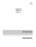
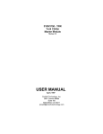
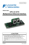
3100/3150 - N2
Johnson Controls
N2
Slave Interface
Module
Revision 1.01
USER MANUAL
January 1996
Updated April, 1998
ProSoft Technology, Inc.
1675 Chester Ave.
Fourth Floor
Bakersfield, CA 93301
[email protected]
Product Revision History
11/16/95
Revision 1.0
Initial release of product
01/21/96
Revision 1.01 - 2
Modifications to support more data objects
Table of Contents
1 Product Specifications ............................................................................................................................2
2 Installation, Configuration and Diagnostics .............................................................................................2
2.1 Card Installation Procedure..............................................................................................................2
2.2 Ladder Logic Overview ....................................................................................................................3
2.2.1 Block Transferring to the module...................................................................................................3
2.2.2 Binary Input Object Data Block [ BTW Block ID 0 ].......................................................................3
2.2.3 Analog Input Object Data Blocks [ BTW Block ID 1 to 5 ] .............................................................4
2.2.4 Module Configuration Block [ BTW Block ID 255 ] ........................................................................4
2.2.5 Block Transferring data from the module.......................................................................................5
2.2.6 Slave Communication Status [ BTR Block ID 0 ] .........................................................................6
2.2.7 Binary Output Write [ BTR Block ID 1 ]..........................................................................................7
2.2.8 Analog Output Point Data Results [ BTR Block ID 2 ] ...................................................................7
3 Communication Cables ..........................................................................................................................8
3.1 3100/3150-N2 To Host Cable...........................................................................................................8
4 Example Ladder Logic - PLC5 ................................................................................................................8
Appendix
Jumper Configurations
Support, Service and Warranty
1
1
Product Specifications
The ProSoft Technology, Inc. 3100/3150-N2 card is a hardware product designed to allow the
Allen-Bradley PLC and SLC platforms to communicate with Johnson Controls N2 compatible host
packages. The 3100/3150-N2 product includes the following functionality:
•
•
•
•
•
•
•
•
•
2
Supports the following N2 Objects:
Binary Input
:
Up to 960 points
Analog Input
:
Up to 300 points
Binary Output
:
Up to 960 points
Analog Output :
Up to 300 points
Supported Command/Subcommands:
0/4
:
Poll Message No Acknowledge
0/5
:
Poll Message with Acknowledge
0/9
:
Status Update
1/1
:
Read Analog Input Attributes
1/2
:
Read Binary Input Attributes
1/3
:
Read Analog Output Attributes
1/4
:
Read Binary Output Attributes
2/1
:
Write Analog Input Attributes
2/2
:
Write Binary Input Attributes
2/3
:
Write Analog Output Attributes
2/4
:
Write Binary Output Attributes
7/2/3 :
Override Analog Output
7/2/4 :
Override Binary Output
F
:
Identify Device Type
The following commands are recognized, and acknowledged, but are not
communicated in any way to the PLC/SLC, and do not return any data:
0/0
:
Time Update
0/8
:
Warm Start
All other commands return a Bad Command Error Code
Configurable through the PLC/SLC data table for the following:
Slave Address (assignable individually for port 1 and 2)
Analog Input Object Count
Binary Input Object Count
Analog Output Object Count
Binary Output Object Count
Operates with the following communication configuration:
Port Type
:
RS-485
Parity
:
None
Stop Bit
:
1
Baud Rate
:
9600
Data Bits
:
8
Comm Timeout :
300 ms
Warning and Alarming functions performed on Analog Input and Binary
Input data types
Change Of State Response buffering
Communication Status Error Codes and statistics returned per port
Memory mapping is pre-assigned to optimize data access and to ease
implementation
Card plugs directly into Allen-Bradley 1771 or 1746 I/O racks
Installation, Configuration and Diagnostics
2.1
Card Installation Procedure
Installation of the 3100/3150-N2 card is easily accomplished. The card comes preprogrammed to support the N2 interface. Installation into a system requires only a few
steps. Following is a step-by-step procedure for getting an application operational:
1. Identify rack and slot location for module.
2. Identify the data files for Block Transfer buffering and N2 data exchange
3. Use existing example logic (See attached) provided on disk as a starting point
2
4.
5.
6.
7.
8.
9.
Modify this logic for correct physical rack and slot locations
Modify the logic for the data file locations to be used
Assure that port jumpers are set for RS-485
Install the card into rack and download ladder logic
Make up an RS-485 cable to the front of the module
Power up equipment and view communication status in data table
Once the hardware has been installed and the necessary programming has been
downloaded to the processor, the system is ready (Presuming all other system
components are safely ready).
2.2
Ladder Logic Overview
Data transfer between the PLC/SLC ladder logic is executed using the standard Block
Transfer commands, BTR/BTW in the PLC, and M0/M1 in the SLC. In order to transfer
the volume of data required to support the application, the ProSoft module ‘pages’ data
through the Block Transfer buffer, allowing a larger volume of data to be written and read
between the ladder logic and the module.
In order for the ProSoft Technology module to function, the processor
must be in the RUN mode, or in the REM RUN mode. If in any other
mode (Fault/PGM), the block transfers between the PLC and the
module will stop, and communications will halt until block transfers
resume.
2.2.1
Block Transferring to the module
Data transfer to the module from the processor is executed through the Block
Transfer Write function. The different types of data which are transferred
require slightly different data block structures, but the basic data structure is:
Word
Description
0
BTW Block ID code
1-63
Data
Although the full physical 64 words of the data buffer may
not be used, the BTW and M0 lengths must be configured
for 64 words, otherwise module operation will be
unpredictable.
BTW Block ID Code: A block page identifier code. This code is used by the
ProSoft module to determine what to do with the data block. Valid codes are:
BTW Code
Description
0
Binary Input Object Data
1-5
Analog Input Object Data
255
Module Configuration Data
Data: The data to be written to the module. The structure of the data is
dependent on the Block ID code. The following sections provide details on the
different structures.
2.2.2
Binary Input Object Data Block [ BTW Block ID 0 ]
The transfer of Binary Input data to the module must occur in a fashion that
matches the structure expected by the module. The module monitors the BTW
Block ID number and decodes the data following it based on this value.
Following are the data structures for each of the blocks:
Example
BTW
Ladder
Buffer Description
0
BTW Block ID
B13:0
1
Binary Pts 1-16
B13:1
2
Binary Pts 17-32
3
B13:2
B13:59
2.2.3
3
60
Binary Pts 33-48
Binary Points 945 to 960
Analog Input Object Data Blocks [ BTW Block ID 1 to 5 ]
The transfer of Analog Input data to the module must occur in a fashion that
matches the structure expected by the module. The module monitors the BTW
Block ID number and decodes the data following it based on this value.
Following are the data structures for each of the blocks:
BTW Block ID 1
Word
0
1 -60
BTW Block ID 2
Word
0
1 -60
BTW Block ID 3
Word
0
1 -60
BTW Block ID 4
Word
0
1 -60
BTW Block ID 5
Word
0
1 -60
Description
BTW Block ID = 1
Analog Input Data points 1 - 60
Description
BTW Block ID = 2
Analog Input Data points 61 - 120
Description
BTW Block ID = 3
Analog Input Data points 121 - 180
Description
BTW Block ID = 4
Analog Input Data points 181 - 240
Description
BTW Block ID = 5
Analog Input Data points 241 - 300
BTW Block ID Code: This value is decoded by the 3100/3150-N2 module to
determine which set of Analog Input data is being transferred to the module.
Analog Input Data: The analog input data values to be transmitted to the N2
host. The analog data values are transferred to the module as integer values
with the range of -32767 to 32767.
2.2.4
Module Configuration Block [ BTW Block ID 255 ]
The ProSoft Technology firmware communication parameters must be
configured at least once when the card is first powered up, and any time
thereafter when the parameters must be changed.
On power up, the module enters into a logical loop waiting to receive
configuration data from the processor. While waiting, the module sets the
second word of the BTR buffer to 255, telling the processor that the module
must be configured before anything else will be done. The module will
continuously perform block transfers until the communications configuration
parameters block is received. Upon receipt, the module will begin execution of
the command list if present, or begin looking for the command list from the
processor. The configuration data block structure which must be transferred
from the processor to the module is as follows:
BTW Block ID 255
PLC
Ladder
Example
N7:0
BTW
Buffer
Word
0
1
4
Description
BTW Block ID = 255
Port #1 Slave Address
N7:1
N7:2
2
3
N7:3
4
N7:4
5
N7:5
6
N7:6
N7:7
N7:8
N7:9
7
8
9
10
Port #2 Slave Address
Binary Input Object Count
- Valid values : 0 to 960
Analog Input Object Count
- Valid values : 0 to 300
Binary Output Object Count
- Valid values : 0 to 960
Analog Output Object Count
- Valid values : 0 to 300
Spare/Future
Spare/Future
Spare/Future
Spare/Future
Example Ladder Program - Appendix
Communication Configuration
N7:0
1
Port 1 Slave Address
N7:1
1
Port 2 Slave Address
N7:2
16
Binary Input Object Count
N7:3
10
Analog Input Object Count
N7:4
16
Binary Output Object Count
N7:5
10
Analog Output Object Count
N7:6
0
Spare
N7:7
0
Spare
N7:8
0
Spare
N7:9
0
Spare
2.2.5
Block Transferring data from the module
Data transfer from the module to the processor is executed through the Block
Transfer Read function. The different types of data which are transferred
require slightly different data block structures, but the basic data structure is:
Word
Description
0
BTR Block ID Code
0 - Slave Port Status
1 - Binary Output Write
2 - Analog Output Write
1
BTW Block ID Code
2-63
Data
Although the full physical 64 words of the data buffer may
not be used, the BTR and M1 lengths must be configured
for 64 words, otherwise module operation will be
unpredictable.
BTR Block ID Code: A block page identifier code. This code is used by the
ladder logic to determine what to do with the data block. Valid codes are:
BTR Code
Description
0
Slave Port Status
1
Binary Output Write Active
2
Analog Output Write Active
BTW Block ID Code: This is the value which the ladder logic uses to setup the
next BTW instruction.
Data: The data to be transferred from the module to the data table in the
PLC/SLC. The structure of the data is dependent on the Block ID code. The
following sections provide details on the different structures.
5
2.2.6
Slave Communication Status [ BTR Block ID 0 ]
The 3100/3150-N2 module monitors communication status and statistics on
each of the N2 ports. The current communication status values are transferred
to the PLC/SLC in the form of a Slave Error Table. The structure of BTR buffer
is as follows:
BTR Block ID 0
Word
0
1
2-21
Description
BTR Block ID
BTW Block ID
Slave Error Table
The Slave Error Code Table is initialized to zero on power up,
and every time the module receives the 255 configuration data
block.
The Slave Error Table is a 20 word block. The location of the Error Table is
determined by the Slave Error Table Pointer parameter in the Configuration
Block. The structure of the data block is as follows:
WORD
DESCRIPTION
Port 1
0
Current port status
1
Last error condition
2
Total Messages to this slave
3
Total Msg responses from this slave
4
Total Msgs seen by this slave
Port 2
5
Current port status
6
Last error condition
7
Total Messages to this slave
8
Total Msg responses from this slave
9
Total Msgs seen by this slave
System Information
10-11
Product Name (ASCII)
12-13
Revision (ASCII)
14
Operating System Rev(ASCII)
15
Production Run Number (ASCII)
16-19
Spare
Current Port Error Status: This value represents the current value of the error
code for the port. This value will only be valid if the port is configured as a
Slave. The possible values are detailed in the following section.
Code
Description
0
All OK
1
Bad Command
2
Checksum Error
3
Recv buffer overflow
5
Command Data Error
16
Data Register Addr out of range
17
Field Data Error
18
Command Rejected
20
Unit not Warm Started
255
TX Timeout – RTS/CTS jumper missing
Last Error Code: This value is the last error code transmitted to the master by
this slave port..
6
Total Messages to This Slave: This value represents the total number of
messages that have matched this slaves address on this port, whether the slave
actually determined them to be good (worthy of response) or not.
Total Message Responses From This Slave: This value represents the
number of good (non-error) responses that the slave has sent to the master on
this port. The presumption is that if the slave is responding, the message was
good.
Total Messages Seen By This Slave: This value represents the total number
of commands seen by the slave on this port, regardless of the slave address.
All counters in the Slave Error Table will rollover to 0 after
reaching 65535
Product Name: These two words represent the product name of the module in
an ASCII representation. In the case of the N2 product, the letters ‘ N2 ‘ should
be displayed when placing the programming software in the ASCII data
representation mode.
Revision : These two words represent the product revision level of the
firmware in an ASCII representation. An example of the data displayed would
be ‘1.00’ when placing the programming software in the ASCII data
representation mode.
Operating System Revision : These two words represent the module’s
internal operating system revision level in an ASCII representation.
Production Run Number: This number represents the ‘batch’ number that
your particular chip belongs to in an ASCII representation.
2.2.7
Binary Output Write [ BTR Block ID 1 ]
The 3100/3150-N2 module accept Binary Output write commands from the host
and transfers the command to the PLC/SLC for handling. The structure of
command to the this data is as follows:
BTR Block ID 1
Word
0
1
2
3
Description
BTR Block ID
BTW Block ID
Bit Address
Control Action
Bit Address: The Bit Address represents the bit which will be acted on . The
ladder logic must decode this address to determine which bit to act on. The
range of addresses will be 0 to 959. The Bit Address corresponds to :
Bit Address = N2 Object Number - 1
Control Action: The action commanded by the Master is transferred in this
word. When the value is a 0, the addressed bit is to be reset, and when the
value is a 1, the addressed bit is to be set.
2.2.8
Analog Output Point Data Results [ BTR Block ID 2 ]
The 3100/3150-N2 module accepts Analog Output write commands from the
host and transfers the command to the PLC/SLC for handling. The structure of
command to the this data is as follows:
7
BTR Block ID 2
Word
0
1
2
3
Description
BTR Block ID
BTW Block ID
Destination Address
Data
Register Address: This value
address in the processor data in
logic must decode this word to
Master. The range of values
corresponds to;
is used by the ladder logic to determine the
which to write the data. The processor ladder
determine where to locate the data from the
will be 0 to 299. The destination address
Register Address = N2 Object Number - 1
Data: The data values written from the host. The values will be 16 bit register
values, and should be placed into an integer file.
3
Communication Cables
The cable connection between the N2 host and the 3100/3150-N2 module is made through the
ports on the front of the module. In the following sections, the cables are detailed.
3.1
3100/3150-N2 To Host Cable
This cable connection is an RS-232 connection. Configuration of the cable is as follows:
ProSoft Module
3100
3150
DB 25 M
DB 9 F
14
TxRxD_A
1
25
TxRxD_B
9
4
RTS
7
5
4
CTS
8
N2 Host
------------------N2------------------N2+
----| jumper between RTS/CTS must be installed
-----
Example Ladder Logic - PLC5
The following ladder logic provides an example of the PLC5 logic necessary to effect data transfer
between the 3100-N2 module and the data table in the PLC. In this example we have setup the
ladder logic data table with the following configuration:
Communication Configuration
N7:0
1
Port 1 Slave Address
N7:1
1
Port 2 Slave Address
N7:2 16
Binary Input Object Count
N7:3 10
Analog Input Object Count
N7:4 16
Binary Output Object Count
N7:5 10
Analog Output Object Count
N7:6
0
Spare
N7:7
0
Spare
N7:8
0
Spare
N7:9
0
Spare
Module Slave Error Status Table
N7:10
Port 1 - Current Status
N7:11
Port 1 - Last Error
N7:12
Port 1 - Total messages to this slave
N7:13
Port 1 - Total responses from this slave
N7:14
Port 1 - Total messages seen by this slave
N7:15
Port 2 - Current Status
N7:16
Port 2 - Last Error
8
N7:17
N7:18
N7:19
N7:20
N7:21
N7:22
N7:23
N7:24
N7:25
N7:26
‘N2’
‘ ’
‘1. ‘
‘ 01‘
‘05’
‘02’
Port 2 - Total messages to this slave
Port 2- Total responses from this slave
Port 2 - Total messages seen by this slave
Product Name
Product Revision
Operating System Level
Batch Number
Spare
Binary Input Image
This is binary information that is to be moved from the PLC to the module reflecting the
on/off status of discrete information
B13/0
BI1
B13/1
BI2
B13/2
BI3
B13/3
BI4
B13/4
BI5
B13/5
BI6
B13/6
BI7
B13/7
BI8
B13/8
BI9
B13/9
BI10
B13/10
BI11
B13/11
BI12
B13/12
BI13
B13/13
BI14
B13/14
BI15
B13/15
BI16
Analog Input Image
This is analog or register information that is to be moved from the PLC to the module.
N10:0
AI1
N10:1
AI2
N10:2
AI3
N10:3
AI4
N10:4
AI5
N10:5
AI6
N10:6
AI7
N10:7
AI8
N10:8
AI9
N10:9
AI10
Binary Output Image
B14/0
B14/1
B14/2
B14/3
B14/4
B14/5
B14/6
B14/7
B14/8
B14/9
B14/10
B14/11
B14/12
B14/13
BO1
BO2
BO3
BO4
BO5
BO6
BO7
BO8
BO9
BO10
BO11
BO12
BO13
BO14
9
B14/14
B14/15
Analog Output Image
N10:50
N10:51
N10:52
N10:53
N10:54
N10:55
N10:56
N10:57
N10:58
N10:59
BO15
BO16
AO1
AO2
AO3
AO4
AO5
AO6
AO7
AO8
AO9
AO10
10
Jumper Configurations
Hardware Overview
When purchasing the ProSoft product, there are two available choices for each platform.
These choices are as follows:
Description
Module provided by ProSoft
ProSoft Cat Num
PLC
SLC
3100
3150
When purchasing the module from ProSoft Technology, many of the jumper
configurations will have been factory set. When purchasing the firmware from ProSoft
Technology and the Allen-Bradley module from another source, particular attention must
be paid to hardware configuration.
Module Jumper Configurations
The following section details the available jumper configurations for the 1771 and 1746
platform solutions. As needed, differences between the module based solutions and the
firmware based solutions are highlighted.
3100/3101 for the 1771 Platform
Following are the jumper positions for the ProSoft Technology 3100 module:
Jumper
JW1
JW2
JW3
JW4
JW5
JW6
JW7
JW8
JW9
3100
N/A
N/A
N/A
Flash Pgm/Run Mode
8 Pt
Not Used
Enabled
RS-485
RS-485
JW1
Watchdog Enable / Disable
Enable
The position of this jumper does not affect the operation of the unit
under normal operations. In order to enable the watchdog function,
simply place the jumper in the Enabled position.
JW4
Flash Pgm/Run Mode Select
Run Position
The position of this jumper should only be changed if needing to
reprogram the MCM FLASH memory. This will only need to be done if
the module is to be upgraded in the field to a later version of firmware.
JW5
Backplane 8/16 point
8 Point
The module should be operated in the 8 point configuration unless
specifically directed otherwise by the factory.
JW7
Battery Enable / Disable
Enabled
This jumper should be placed in the Enabled position when the module
is powered up. Although not critical to the operation of the module,
this will back up some data registers in the module during a power
failure or reset.
JW8/9
RS Configuration for Port 1 and 2
Set for RS-485
The default from factory is RS-232. Change the jumper to RS-485, or
2-wire mode.
11
3150/3151 for the 1746 Platform
Following are the jumper positions for the ProSoft Technology 3150 module:
Jumper
JW1
JW2
JW3
JW4
JW1/2
3150
As Needed
As Needed
N/A
N/A
RS configuration for port 1 and 2
See following diagram
The default from factory is RS-232, but all options are supported by the
firmware
Communication Port
Jumper Settings for 3150/3151 Modules - JW1 & JW2
RS-232
RS-422
4-wire
RS-485
2-wire
RS-232
RS-422
4-wire
RS-485
2-wire
For the 3150/3151-N2 Solution, use the RS-485/2-wire
jumper configuration
12
Support, Service and Warranty
Technical Support
ProSoft Technology survives on its ability to provide meaningful support to its
customers. Should any questions or problems arise, please feel free to contact us at:
Factory/Technical Support
ProSoft Technology, Inc.
9801 Camino Media, Suite 105
Bakersfield, CA 93311
(805) 664-7208
(800) 326-7066
(805) 664-7233 (fax)
E-mail address: [email protected]
Web Site : http://www.prosoft-technology.com
Before calling for support, please prepare yourself for the call. In order to provide the
best and quickest support possible, we will most likely ask for the following information
(you may wish to fax it to us prior to calling):
1.
2.
3.
4.
5.
Product Version Number
Configuration Information
Communication Configuration
Master Command List
Jumper positions
System hierachy
Physical connection information
RS-232, 422 or 485
Cable configuration
Module Operation
Block Transfers operation
LED patterns
An after-hours answering service (on the Bakersfield number) allows pager access to
one of our qualified technical and/or application support engineers at any time to answer
the questions that are important to you.
Module Service and Repair
The ProSoft product is an electronic product, designed and manufactured to function
under somewhat adverse conditions. As with any product, through age, misapplication,
or any one of many possible problems, the card may require repair.
When purchased from ProSoft Technology, the module has a one year parts and labor
warranty according to the limits specified in the warranty. Replacement and/or returns
should be directed to the distributor from whom the product was purchased. If you need
to return the card for repair, it is first necessary to obtain an RMA number from ProSoft
Technology. Please call the factory for this number and display the number prominently
on the outside of the shipping carton used to return the card.
General Warranty Policy
ProSoft Technology, Inc. (Hereinafter referred to as ProSoft) warrants that the Product
shall conform to and perform in accordance with published technical specifications and
the accompanying written materials, and shall be free of defects in materials and
workmanship, for the period of time herein indicated, such warranty period commencing
upon receipt of the Product.
This warranty is limited to the repair and/or replacement, at ProSoft's election, of
defective or non-conforming Product, and ProSoft shall not be responsible for the failure
of the Product to perform specified functions, or any other non-conformance caused by
or attributable to: (a) any misapplication of misuse of the Product; (b) failure of Customer
to adhere to any of ProSoft's specifications or instructions; (c) neglect of, abuse of, or
13
accident to, the Product; or (d) any associated or complementary equipment or software
not furnished by ProSoft.
Limited warranty service may be obtained by delivering the Product to ProSoft and
providing proof of purchase or receipt date. Customer agrees to insure the Product or
assume the risk of loss or damage in transit, to prepay shipping charges to ProSoft, and
to use the original shipping container or equivalent. Contact ProSoft Customer Service
at (805) 664-7208 for further information.
Limitation of Liability
EXCEPT AS EXPRESSLY PROVIDED HEREIN, PROSOFT MAKES NO WARRANT OF
ANY KIND, EXPRESSED OR IMPLIED, WITH RESPECT TO ANY EQUIPMENT,
PARTS OR SERVICES PROVIDED PURSUANT TO THIS AGREEMENT, INCLUDING
BUT NOT LIMITED TO THE IMPLIED WARRANTIES OF MERCHANT ABILITY AND
FITNESS FOR A PARTICULAR PURPOSE. NEITHER PROSOFT OR ITS DEALER
SHALL BE LIABLE FOR ANY OTHER DAMAGES, INCLUDING BUT NOT LIMITED TO
DIRECT, INDIRECT, INCIDENTAL, SPECIAL OR CONSEQUENTIAL DAMAGES,
WHETHER IN AN ACTION IN CONTRACT OR TORT (INCLUDING NEGLIGENCE AND
STRICT LIABILITY), SUCH AS, BUT NOT LIMITED TO, LOSS OF ANTICIPATED
PROFITS OR BENEFITS RESULTING FROM, OR ARISING OUT OF, OR IN
CONNECTION WITH THE USE OR FURNISHING OF EQUIPMENT, PARTS OR
SERVICES HEREUNDER OR THE PERFORMANCE, USE OR INABILITY TO USE THE
SAME, EVEN IF PROSOFT OR ITS DEALER'S TOTAL LIABILITY EXCEED THE PRICE
PAID FOR THE PRODUCT.
Where directed by State Law, some of the above exclusions or limitations may not be
applicable in some states. This warranty provides specific legal rights; other rights that
vary from state to state may also exist. This warranty shall not be applicable to the
extent that any provisions of this warranty is prohibited by any Federal, State or
Municipal Law that cannot be preempted.
Hardware Product Warranty Details
Warranty Period : ProSoft warranties hardware product for a period of one (1) year.
Warranty Procedure : Upon return of the hardware Product ProSoft will, at its option,
repair or replace Product at no additional charge, freight prepaid, except as set forth
below. Repair parts and replacement Product will be furnished on an exchange basis
and will be either reconditioned or new. All replaced Product and parts become the
property of ProSoft. If ProSoft determines that the Product is not under warranty, it will,
at the Customer's option, repair the Product using current ProSoft standard rates for
parts and labor, and return the Product freight collect.
14
ProSoft Technology 1997
Program Listing Report
Wed Dec 10, 1997
PLC-5/15
File N2_PLC5
Page 1
Rung 2:0
Rung 2:0
BT READ AND REGISTER TRANSFER FROM MODULE DECODING
BT READ from module. If BT READ Block ID is 0, then transfers the module's
error table, else check to see if an A0 or B0 command has been received.
|BT READ
|ENABLE
| BT WRITE
BT READ
|
| ENABLE
FROM
|
|
MODULE
|
|
N7:300
N7:400
+BTR--------------------+
|
+----]/[--------]/[---------------------------------------------------+----------------+BLOCK TRANSFER READ
+-(EN)+-+
|
15
15
|
|Rack
00|
| |
|
|
|Group
2+-(DN)| |
|
|
|Module
0|
| |
|
|
|Control block
N7:400+-(ER)| |
|
|
|Data file
N7:410|
| |
|
|
|Length
64|
| |
|
|
|Continuous
N|
| |
|
|
+-----------------------+
| |
|
|
DECODE
ERROR
| |
|
|
BT READ
STATUS
| |
|
|
BLOCK ID
TABLE
| |
|
|+EQU---------------+
+COP---------------+| |
|
++EQUAL
+------+COPY FILE
++ |
|
||Source A
N7:410|
|Source
#N7:412|| |
|
||
3|
|Destination #N7:10|| |
|
||Source B
0|
|Length
20|| |
|
||
|
+------------------+| |
|
|+------------------+
| |
|
|
DECODE
B0 CMD
|B0 CMD
| |
|
|
BT READ
ACTION
|
| |
|
|
BLOCK ID
| |
|
|+EQU---------------+
N7:413
B14
| |
|
++EQUAL
++---] [--------(L)----+---+ |
|
||Source A
N7:410||
0
[N7:412] |
| |
|
||
3||B0 CMD
|B0 CMD
|
| |
|
||Source B
1||ACTION
|
|
| |
|
||
|| N7:413
B14
|
| |
|
|+------------------++---]/[--------(U)----+
| |
|
|
0
[N7:412]
| |
|
|
DECODE
MOVE CMD
| |
|
|
BT READ
AOUT
| |
|
|
BLOCK ID
| |
|
|+EQU---------------+ +MOV--------------------+| |
|
++EQUAL
+-+MOVE
++ |
|
||Source A
N7:410| |Source
N7:413|| |
|
||
3| |
0|| |
|
||Source B
2| |Destination N11[N7:412]|| |
|
||
| |
0|| |
|
|+------------------+ +-----------------------+| |
|
|
ENCODES
| |
|
|
BT WRITE
| |
|
|
BLOCK ID
| |
|
|
+MOV---------------+| |
|
+--------------------------+MOVE
++ |
|
|
|Source
N7:411|| |
|
|
|
0|| |
|
|
|Destination N7:310|| |
|
|
|
81|| |
|
|
+------------------+| |
|
|
| |
|
|
| |
|
|
| |
|
|
| |
|
|
| |
|
|
| |
|
|
| |
|
|
| |
|
|
| |
|
|
| |
|
|
| |
|
vvv
vvv|
15
ProSoft Technology 1997
Program Listing Report
Wed Dec 10, 1997
PLC-5/15
|
|
|
|
|
|
|
|
|
|
|
File N2_PLC5
Page 2
Rung 2:0
^^^
^^^|
|USER CFG
ENCODES
| |
|DOWNLOAD
BT WRITE
| |
|SELECT
BLOCK ID
| |
|
B3
+MOV---------------+| |
+---] [--------------------+MOVE
++ |
0
|Source
255| |
|
| |
|Destination N7:310| |
|
81| |
+------------------+ |
Rung 2:1
WRITES DATA OR CONFIGURATION BLOCK TO MODULE
Based on the value in the BTW Block ID, either BI data or AI is written to the
module. Note that the Block ID numbers are controlled by the module based on
the configuration values entered in the 255 configuration block.
| BT READ
|BT WRITE
DECODE
WRITE TO
|
| ENABLE
|ENABLE
BT WRITE
BT WRITE
|
|
BLOCK
BUFFER
|
|
N7:400
N7:300
+EQU---------------+ +COP--------------------+ |
+----]/[--------]/[--------------------------------------------------++EQUAL
+--+COPY FILE
++-+
|
15
15
||Source A
N7:310| |Source
#B13:0|| |
|
||
81| |Destination
#N7:311|| |
|
||Source B
0| |Length
60|| |
|
||
| +-----------------------+| |
|
|+------------------+
| |
|
|
DECODE
WRITE TO
| |
|
|
BT WRITE
BT WRITE
| |
|
|
BLOCK
BUFFER
| |
|
|+EQU---------------+ +COP--------------------+| |
|
++EQUAL
+--+COPY FILE
++ |
|
||Source A
N7:310| |Source
#N10:0|| |
|
||
81| |Destination
#N7:311|| |
|
||Source B
1| |Length
60|| |
|
||
| +-----------------------+| |
|
|+------------------+
| |
|
|
DECODE
WRITE TO
| |
|
|
BT WRITE
BT WRITE
| |
|
|
BLOCK
BUFFER
| |
|
|+EQU---------------+ +COP--------------------+ | |
|
++EQUAL
+++COPY FILE
+++ |
|
||Source A
N7:310|||Source
#N7:0||| |
|
||
81|||Destination
#N7:311||| |
|
||Source B
255|||Length
10||| |
|
||
||+-----------------------+|| |
|
|+------------------+|
USER CFG || |
|
|
|
DOWNLOAD || |
|
|
|
SELECT
|| |
|
|
|
B3
|| |
|
|
+------------------(U)----+| |
|
|
0
| |
|
|
BT WRITE
| |
|
|
TO MODULE
| |
|
|
+BTW--------------------+
| |
|
+-----------------+BLOCK TRANSFER WRITE
+-(EN)+ |
|
|Rack
00|
|
|
|Group
2+-(DN) |
|
|Module
0|
|
|
|Control block
N7:300+-(ER) |
|
|Data file
N7:310|
|
|
|Length
64|
|
|
|Continuous
N|
|
|
+-----------------------+
|
Rung 2:2
|
|
+------------------------------------------------------------------------[END OF FILE]---------------------------------+
|
|
16
ProSoft Technology 1997
Data Table Report
Address
N7:0
N7:10
N7:20
N7:30
N7:40
N7:50
N7:60
N7:70
N7:80
N7:90
N7:100
N7:110
N7:120
N7:130
0
1
16
20018
0
0
1
1
1
1
0
0
0
0
0
N10:0
Address
N10:0
N10:10
N10:20
N10:30
N10:40
N10:50
N10:60
N10:70
N10:80
N10:90
N10:100
N10:110
N10:120
N10:130
N10:140
N10:150
N10:160
N10:170
N10:180
N10:190
0
120
1
0
0
0
0
0
0
0
0
0
0
0
0
0
0
0
0
0
0
PLC-5/15
1
2
1
16
16 -28548
8224 12590
0
0
0
0
1
3
1
4
1
16
1
1
1
2
1
5
1
15
0
0
0
0
1
2
0
0
0
0
0
0
0
0
0
0
0
0
0
0
0
0
0
0
0
0
3
4
10
16
18494 -28548
12337 12342
0
0
0
0
0
10
20
10
0
10
0
80
0
80
0
1
0
80
0
0
0
0
3
0
0
0
0
0
0
0
0
0
0
0
0
0
0
0
0
0
0
0
0
4
0
0
0
0
0
0
0
0
0
0
0
0
0
0
0
0
0
0
0
0
0
0
0
0
0
0
0
0
0
0
0
0
0
0
0
0
0
0
0
0
5
10
16
8242
0
0
50
70
0
90
95
4000
3084
0
0
6
5
6
0
0
0
0
0
0
0
0
0
0
0
0
0
0
0
0
0
0
0
0
Wed Dec 10, 1997
Page 7
Data Table File N7:0
File N2_PLC5
7
0
0
0
0
0
0
0
0
0
0
0
0
0
0
8
0
1263
0
0
0
0
0
0
0
0
0
0
0
0
7
0
0
0
0
0
0
0
0
0
0
0
0
0
0
0
0
0
0
0
0
8
0
0
0
0
0
0
0
0
0
0
0
0
0
0
0
0
0
0
0
0
17
9
0
678
0
0
0
0
0
0
0
0
0
0
0
0
0
1263
0
0
0
0
0
0
0
0
0
0
0
0
9
1
0
0
0
0
0
0
0
0
0
0
0
0
0
0
0
0
0
0
0
1
0
0
0
0
0
0
0
0
0
0
0
0
0
0
0
0
0
0
0
ProSoft Technology 1997
Data Table Report
Address
N11:0
N11:10
N11:20
N11:30
N11:40
N11:50
N11:60
N11:70
N11:80
N11:90
B13:0
Address
B13:0
B13:1
B13:2
B13:3
B13:4
B13:5
B13:6
B13:7
B13:8
B13:9
B13:10
B13:11
B13:12
B13:13
B13:14
B13:15
B13:16
B13:17
B13:18
B13:19
B13:20
B13:21
B13:22
B13:23
B13:24
B13:25
B13:26
B13:27
B13:28
B13:29
B13:30
B13:31
B13:32
B13:33
B13:34
B13:35
B13:36
B13:37
B13:38
B13:39
B13:40
B13:41
B13:42
B13:43
B13:44
B13:45
B13:46
B13:47
B13:48
B13:49
B13:50
B13:51
B13:52
B13:53
B13:54
B13:55
B13:56
B13:57
B13:58
B13:59
0
0
0
0
0
0
0
0
0
0
0
1
55
0
0
0
0
0
0
0
0
0
15
0000
1111
0000
0000
0000
0000
0000
0000
0000
0000
0000
0000
0000
0000
0000
0000
0000
0000
0000
0000
0000
0000
0000
0000
0000
0000
0000
0000
0000
0000
0000
0000
0000
0000
0000
0000
0000
0000
0000
0000
0000
0000
0000
0000
0000
0000
0000
0000
0000
0000
0000
0000
0000
0000
0000
0000
0000
0000
0000
0000
PLC-5/15
2
55
0
0
0
0
0
0
0
0
0
Data
0000 1111
1111 0000
0000 0000
0000 0000
0000 0000
0000 0000
0000 0000
0000 0000
0000 0000
0000 0000
0000 0000
0000 0000
0000 0000
0000 0000
0000 0000
0000 0000
0000 0000
0000 0000
0000 0000
0000 0000
0000 0000
0000 0000
0000 0000
0000 0000
0000 0000
0000 0000
0000 0000
0000 0000
0000 0000
0000 0000
0000 0000
0000 0000
0000 0000
0000 0000
0000 0000
0000 0000
0000 0000
0000 0000
0000 0000
0000 0000
0000 0000
0000 0000
0000 0000
0000 0000
0000 0000
0000 0000
0000 0000
0000 0000
0000 0000
0000 0000
0000 0000
0000 0000
0000 0000
0000 0000
0000 0000
0000 0000
0000 0000
0000 0000
0000 0000
0000 0000
3
55
0
0
0
0
0
0
0
0
0
4
55
0
0
0
0
0
0
0
0
0
5
55
0
0
0
0
0
0
0
0
0
Wed Dec 10, 1997
Page 12
Data Table File N11:0
File N2_PLC5
6
55
0
0
0
0
0
0
0
0
0
7
55
0
0
0
0
0
0
0
0
0
0
1111
0000
0001
0001
0001
0000
0000
0000
0000
0000
0000
0000
0000
0000
0000
0000
0000
0000
0000
0000
0000
0000
0000
0000
0000
0000
0000
0000
0000
0000
0000
0000
0000
0000
0000
0000
0000
0000
0000
0000
0000
0000
0000
0000
0000
0000
0000
0000
0000
0000
0000
0000
0000
0000
0000
0000
0000
0000
0000
0000
18
8
55
0
0
0
0
0
0
0
0
0
9
55
0
0
0
0
0
0
0
0
0
ProSoft Technology 1997
Data Table Report
Address
B14:0
B14:1
B14:2
B14:3
B14:4
B14:5
B14:6
B14:7
B14:8
B14:9
B14:10
B14:11
B14:12
B14:13
B14:14
B14:15
B14:16
B14:17
B14:18
B14:19
B14:20
B14:21
B14:22
B14:23
B14:24
B14:25
B14:26
B14:27
B14:28
B14:29
B14:30
B14:31
B14:32
B14:33
B14:34
B14:35
B14:36
B14:37
B14:38
B14:39
B14:40
B14:41
B14:42
B14:43
B14:44
B14:45
B14:46
B14:47
B14:48
B14:49
B14:50
B14:51
B14:52
B14:53
B14:54
B14:55
B14:56
B14:57
B14:58
B14:59
B14:60
15
0000
0000
0000
0000
0000
0000
0000
0000
0000
0000
0000
0000
0000
0000
0000
0000
0000
0000
0000
0000
0000
0000
0000
0000
0000
0000
0000
0000
0000
0000
0000
0000
0000
0000
0000
0000
0000
0000
0000
0000
0000
0000
0000
0000
0000
0000
0000
0000
0000
0000
0000
0000
0000
0000
0000
0000
0000
0000
0000
0000
0000
Data
0000 0000
0000 0000
0000 0000
0000 0000
0000 0000
0000 0000
0000 0000
0000 0000
0000 0000
0000 0000
0000 0000
0000 0000
0000 0000
0000 0000
0000 0000
0000 0000
0000 0000
0000 0000
0000 0000
0000 0000
0000 0000
0000 0000
0000 0000
0000 0000
0000 0000
0000 0000
0000 0000
0000 0000
0000 0000
0000 0000
0000 0000
0000 0000
0000 0000
0000 0000
0000 0000
0000 0000
0000 0000
0000 0000
0000 0000
0000 0000
0000 0000
0000 0000
0000 0000
0000 0000
0000 0000
0000 0000
0000 0000
0000 0000
0000 0000
0000 0000
0000 0000
0000 0000
0000 0000
0000 0000
0000 0000
0000 0000
0000 0000
0000 0000
0000 0000
0000 0000
0000 0000
PLC-5/15
File N2_PLC5
0
0001
0000
0000
0000
0000
0000
0000
0000
0000
0000
0000
0000
0000
0000
0000
0000
0000
0000
0000
0000
0000
0000
0000
0000
0000
0000
0000
0000
0000
0000
0000
0000
0000
0000
0000
0000
0000
0000
0000
0000
0000
0000
0000
0000
0000
0000
0000
0000
0000
0000
0000
0000
0000
0000
0000
0000
0000
0000
0000
0000
0000
19
Wed Dec 10, 1997
Page 15
Data Table File B14:0