1
3 Framework
3.1 Rear Panel
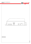
The rear panel is shown as below.
Refer to the following sheet for detailed information.
Interface Name
Connector
VIDEO OUT
Video output port
AC 24V/ DC 12V
Power port
STATUS
Indicatin Light
BNC
Output analog video signal.
Power port.
Input 12V DC or 24V AC.
Red light
System boot up: red light is on
Safe mode: red light flashes
System upgrades: red light flashes
System resets: red light flashes.
Green light
Normal working status: green light
is on.
Display record status: if recording
green light flashes.
Yellow light
Wireless data transmission: yellow
light flashes.
Detect the wireless device: yellow
light is on.
Current series does not support this
function right now.
3G/WIFI port
IN
Function
Alarm input port
I/O port
Alarm input port 1.
Receive the signal from external
alarm device.
Alarm output port.
Send alarm signal to alarm device.
NO: Normal open alarm output port.
C: Alarm output common port.
NO
C
1-ch alarm output
G
GND
A
RS485 port
RS485- port.
B
RS485 port
RS485+port.
Alarm input ground port.
12