1
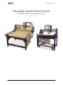
Quick Start Guide Page -1- ShopBot Quick-Start Guide For PRS Alpha and Standard Tools Software versions 3.8 and above Copyright 2013 ShopBot Tools, Inc Quick Start Guide Page -2- About this guide This document is intended as a helpful “Quick Start” guide to help you get up and running with your new Shopbot. It is an abbreviated version of the full user’s manual. For more detailed information on any of these topics, please reference the full manual. There is also a list of resources on the back page for information from other sources. This guide will reference V-Carve Pro in several sections and assumes that you have a basic familiarity with the software. If you are using another CAD/CAM system then those directions may not apply to you. Contents Section 1: Software setup and orientation The first step: loading the software and drivers Connecting the Shopbot to your computer Loading the correct settings file Switching from English to metric units Getting to know the Shopbot control software Using the Keypad Testing each axis Understanding axis orientation Testing your spindle/router Section 2: Technical basics & planning your cuts Safety: a few basic rules Selecting the right bit for your project Calculating feeds and speeds Changing bits Holding down material for cutting Holding small parts within the material Section 3: Running a cut file Zeroing the Z axis Zeroing the XY axes Warming up the spindle Previewing a part file Daily checklist Resources Copyright 2013 ShopBot Tools, Inc Quick Start Guide Page -3- Section 1: Software setup and orientation This section will walk you through installing the software and loading the correct settings for your machine. It will also explain some fundamentals of the control software including basic commands, understanding axis orientation, and running the various components (motors, spindle, etc) outside of a part file. The first step: Loading the Software and drivers Do not connect the Shopbot to your computer before installing the software and drivers! Special note for schools and large companies: This software runs best with full administrative permissions enabled. We strongly advise against setting up separate admin and user accounts on the control computer. For international customers: The computer used to run the machine MUST have the language set to United States English in order for the software to run correctly. Connect the USB flash drive to your computer to install the software. Double-click on “Install_Shopbot” to run the installation. Once the installation completes, you should see four new icons on your screen: Shopbot 3, Shopbot Editor, V-Carve Pro ShopBot Edition, and Partworks 3D. Copyright 2013 ShopBot Tools, Inc Quick Start Guide Page -4- Connecting the Shopbot to your computer Connect the silver (or white) USB cable from the Shopbot control box to your computer. This cable may still be coiled inside the control box if it had not been removed during installation. You will also need to connect the RPM controller from your VFD into a separate USB port on your computer. Loading the correct settings file All of our machines are controlled by the same software, so it's important that we let the program know what kind of machine we are using. You can easily set all settings at once by loading a default settings file. You will be prompted to load a default settings file for your machine the first time you open the program. The following screen should appear: For new machines (built after 2007), double-click on PRS Shopbots. Then choose whether you have a Standard or Alpha model. Last, choose the correct table size for your machine. This will put you back onto the main screen. Copyright 2013 ShopBot Tools, Inc Quick Start Guide Page -5- Getting to know the Shopbot control software The Shopbot control software works in two modes: “Easy mode” (by default) shows only the necessary functions to set up and run a cut file. “Full mode” shows all available functions and settings. You can switch between the two modes by clicking on the Help/options button in the red position window. Copyright 2013 ShopBot Tools, Inc Quick Start Guide Page -6- Switching from inches to millimeters: If you prefer to work in metric units, click the help button in the red position window, then choose the Settings button from the window that appears (as shown below left). Change the first field from inches to millimeters. Then click OK at the bottom right corner of the window to save your changes. Testing each axis using the keypad Turn the control box ON if you have not already done so. Click on the yellow keypad window icon within the position window (reference the chart for clarification). If the icon is not visible, click “cut part” to enable move/cut mode, and then click “cancel” when prompted to choose a file. Copyright 2013 ShopBot Tools, Inc Quick Start Guide Page -7- Understanding axis orientation It’s essential to understand how the X, Y, and Z axes are oriented on your machine, and how this relates to job setup in your CAD/CAM software. Shown below is an example of a job in V-Carve Pro and its corresponding orientation on both Gantry and Buddy models. The bottom corner is referred to as the XY home location or “zero zero.” We will explain more about the XY home location in section #- zeroing the X and Y axes. For right now, just make sure that you understand the axis orientation on your machine. Copyright 2013 ShopBot Tools, Inc Quick Start Guide Page -8- Testing your router/spindle First, locate the key attached to your collet wrench. This will have been located either inside your control box or one of the hardware boxes included with your shipment. Insert this key into the safety lockout on your main control box, and turn the key to ENGAGE. For routers: Make sure that the router’s power switch is in the ON position before proceeding. In the main console window, type K to bring up the keypad move command. Notice the output toggle switches at the bottom of this window. Click switch #1 to turn this output on. This should start the router/spindle for PRS Standard Tools. For PRS Alpha models: after toggling output 1, press the green START button on your remote stop pendant. To turn the spindle off, click the output 1 switch again or close the keypad window. All machines: turn output 1 on through the keypad Alpha models only: press the start button Copyright 2013 ShopBot Tools, Inc Quick Start Guide Page -9- Setting up for RPM control The following section only applies to Shopbots equipped with a spindle. Skip this step if you have a router. If you have not already done so, connect the RPM controller into your computer. This is the black USB plug coming from the VFD. Do not plug it into the hub alongside the main Shopbot USB; it should go straight into an empty port on your computer. In the main console window, click on Tools > Spindle RPM control and then drag this box below the position window to keep it out of your way. It must remain open at all times in order for the software to communicate with the VFD and change RPM. Now click on “RPM” in the left corner of this box. You will see a settings window appear. Change the following parameters: Start when SB3 Starts: 1 Hertz: 60 (this setting is for the US and Canada. It may vary by country). Hertz Scale: 60 VFD 1: Yaskawa V1000 VFD 2: (leave blank, this setting is not used) Now click OK to save your settings. To test the function of the RPM controller, turn on the spindle and then click on the listed RPM value in your spindle control window. Change it to something different and then hit Enter. The value on the VFD’s display should match what you just entered at the computer. Copyright 2013 ShopBot Tools, Inc Quick Start Guide Page -10- Section 2: technical basics & planning your cuts This section provides an overview of some basics you need to know to safely and efficiently plan your projects. Keep in mind this this is not a full comprehensive guide. More information can be found in your user’s manual, or online from the resources listed in the back of this guide. Safety: a few basic rules Learn and understand safe use of the machine. Do not allow untrained individuals to operate the machine without supervision. Be aware of the location of the Emergency Stop switches at all times. Eye and ear protection MUST be worn by the machine operator as well as any bystanders or observers. Flying sawdust, material chips, and other debris can cause serious eye injury. Wear closed-toe shoes at all times. Make sure that your material is properly secured before cutting, and be aware of any small parts that may come loose after being cut out. If a small part catches the edge of a spinning bit, it can be thrown forcefully in any direction, causing injury or damage. Never place your hands on the rails of the ShopBot. Be aware that the machine may move unexpectedly in any direction, which can cause serious injury if your hands are in the path of movement. Never wear gloves while operating the machine. As with any power tool, a glove can get caught in moving or spinning parts and pull your hand into the machinery. Never leave a machine running and unattended. Understand that a spinning tool generates friction and heat, creating a risk of fire. This risk is minimized by using correct chip load (read more about this in section 2), using sharp bits, and by always doublechecking your files before cutting. Be prepared to pause or stop the cut if something seems incorrect or unsafe. Keep a working fire extinguisher within reach of the machine, for the reasons listed above. Copyright 2013 ShopBot Tools, Inc Quick Start Guide Page -11- Selecting the right bit for your project Bit material: Router bits are made from a variety of materials. The most common are solid carbide, carbide-tipped steel, and high-speed steel. Both solid carbide and carbidetipped are good choices. We do not recommend using high-speed steel bits as they dull quickly and must be re-sharpened. Flute type: There are four basic flute types: Straight, spiral up-cut, spiral down-cut, and compression. Each type has its own advantages and disadvantages, which are outlined in the chart below. Good edge quality on most materials May chip or fray top face, good quality on bottom face when through-cutting Moderate chip clearing abilities Excels at clearing chips and dissipating heat, especially with “o-flute” bits Upwards force may cause part lifting Ideal for: general-purpose cutting Ideal for: plastics, aluminum, or any material where heat buildup is a concern Best edge quality on top face, may chip or fray bottom face when through-cutting May compact chips in a groove Clean edge on both top and bottom face Designed to cut veneered or laminated materials at full depth in one pass Downwards force may help with cutting thin sheets Ideal for: plywood and laminates (pocketing) Ideal for: plywood and laminates (profile cutting) Copyright 2013 ShopBot Tools, Inc Quick Start Guide Page -12- What’s the difference between a square-end bit and an end mill? An end mill has cutting flutes that extend across the bottom (end) of the bit. It is designed for plungecutting as well as lateral cutting. “Square-end” is simply a description of end shape. Square-end bits are not always end mills, and end mills do not always have square ends. The first image below shows a true end mill, and the second shows a straight-fluted, square-end bit that is not an end mill. A ramp-in must be applied to a toolpath when using this type of bit. Number of flutes: The number of flutes on a bit is essential to calculating proper feed and speed rates. For most applications you can use a bit with 1, 2, or 3 flutes, but you must adjust your reed rates and RPM accordingly to maintain proper chip load. End shape: Straight and up-spiral bits come in a variety of end shapes. Square ends are most common, and are a good choice for creating pockets and grooves, profile cutting, simple lettering, and drilling operations. Ball (or rounded) ends are best for 3D carving. V-carve bits are often used to create complex letters for sign making. They can also be used to chamfer edges and create countersinks for screw holes. Calculating feeds/speed with Chip Load: Chip load refers to the actual thickness of the chip cut by each revolution of the cutter. It is the measurement that all feed/speed calculations are based on. A spinning bit generates friction and heat as it moves through the material, and part of this heat is pulled away by the flying chips. A larger chip load pulls away more heat, but also puts more stress on the cutter. Each material has its own ideal chip load range that balances heat dissipation with cutter stress. A basic chart for common materials is available in the SB3 software. Click on Tools > Chip Load Calculator, then click on Chip Load Help. You can use this chart along with the Chip Load Calculator to determine a good starting speed for each toolpath. When calculating feeds/speeds for a toolpath, do not rely on the defaults in your tool database. Those values are only placeholders and are not intended for any particular material. Copyright 2013 ShopBot Tools, Inc Quick Start Guide Page -13- Changing bits Note: Spindles and routers have different collet styles, so instructions for both are included. Make sure that collet and nut are completely clean. A dirty collet will not grip the bit properly and can cause it to slip during the cut. Use a wire brush, compressed air, and/or mineral spirits to remove dust or excess grease. (For spindles only): Before inserting the bit, press the collet into the nut and listen for the “click.” If you have trouble, try pressing it in at a slight angle. Confirm that the collet is snapped in by holding the nut upside-down and letting the collet hang freely. (For routers only): The router collet and nut are held together by a retaining clip. It is not necessary to disassemble the components for cleaning or bit changes. Slide the bit into the collet. Make sure that the collet grips only the shank of the bit, keeping any parts of the flute outside of the collet. Ideally, the shank of the bit should fill up at least 75% of the collet. Remember that more gripping surface = better hold. For spindles: snap the collet into the nut, then flip it over to make sure it is snapped in securely Check that no part of the flute enters the collet Now thread the collet nut onto the router or spindle. It should go on very easily. If you encounter resistance, do NOT apply more force. Stop and try again until it goes smoothly. Once the nut is finger-tight, check the bit again to make sure that it has not slipped, and then use the included wrenches to fully tighten the nut. Copyright 2013 ShopBot Tools, Inc Quick Start Guide Page -14- Holding down material for cutting Choosing the right hold-down method for your project can be challenging, but it is an essential part of project planning and should not be treated as an afterthought. Not only does the work piece need to be held securely, but you need to be aware of what will happen to parts as they are cut from the surrounding material. Small parts can be caught by the cutter and thrown across the room, causing serious injury or damage. The following information is a brief overview to help you get started. You can find further information by searching online for any of these methods. The Shopbot user’s forum (www.talkshopbot.com/forum) is another great resource where you can see what other users have done and share tips and advice. Screws If you have a spoilboard set up, you can screw the workpiece directly to the table. This is a quick and easy method that works well for most materials. However, this requires careful planning to make sure that all the screws are clear of the cut path. With larger jobs you may want to consider creating a hold down toolpath based on the location of other toolpaths in the file. This will create clearance holes for the screws in locations that you know are safe. When using an end mill for drilling, there is very little lateral force on the piece so less holding power is needed. A few clamps on the edge of the board will be sufficient to complete this initial run. T-track tables and rails The Shopbot Buddy has an aluminum table base that is ideal for setting up moveable clamps and fixtures. On full-size machines, you can set up your own system using T-track rails (available from woodworking supply stores), inlaid into the wood table. If you use this method, be sure that the rails sit low enough below the surface that they are out of the way when through-cutting. Clamps Whether you are working with a T-track table or a spoilboard, there are a variety of clamps that you can use to secure your material. Clamps offer very secure holding power, and are ideal when you do not have excess material to drive screws into. However, they usually require more planning than other methods because of the vertical clearance required. Press-fit jigs Since most of the cutting force is lateral, a tight press-fit jig can sometimes provide sufficient holding force. You may want to consider using additional hold-downs if cutting aggressively or using a spiral up-cut bit. Adhesive Double-sided duct tape, carpet tape, and foam tape can provide excellent holding abilities. Both the table and work piece must be clean, flat, and dust-free. More surface area = more holding power, so this may not be a good choice for small projects. When through-cutting, Copyright 2013 ShopBot Tools, Inc Quick Start Guide Page -15- make sure that the tape stays out of the cut path. It may gum up the cutting edge, reducing cut quality for the rest of the part. Spray adhesive is another option. 3M makes an excellent product called Super 77, which forms an extremely strong bond within 2-3 minutes. To avoid damaging your table, bond the workpiece to a scrap board that is clean and flat, then clamp or screw this board to your table. Some people prefer to glue a layer of paper between the workpiece and support board. This weakens the bond, but it makes removal much easier. Try both methods on some scrap so that you can compare for yourself. Vacuum hold-down systems A well-built vacuum system can be one of the most convenient and effective hold-down methods. It is ideal for repetitive cutting of plywood and other sheet materials. Shopbot offers several kits for full-table vacuum systems on our Gantry tools. For the Buddy Tools, you might consider building your own vacuum table or using a modular “puck” system. There are many resources online for instructions on building small-scale vacuum tables. A Google search will get you started. Holding small parts within the material Once you secure your material, you still need to consider what will happen to parts as you cut them out. Large parts may shift as they are cut free, leading to a small gouge or notch along the edge. Smaller parts can be destroyed or even thrown across the room by the cutter. There are two ways that you can handle this from within the software. The first option is to create tabs, or leftover “bridges” of material between the part and its surrounding area. Most CAM programs will have an automated feature for this. The feature for V-Carve Pro is shown here. Further information is available within either program by clicking on Help > Help Contents. Adding tabs in V-Carve Pro Example of tabs on a part A second option is to leave an “onion skin,” or very thin layer of material at the bottom of a profile cut. Just set the final cut depth at slightly less than the thickness of your material Copyright 2013 ShopBot Tools, Inc Quick Start Guide Page -16- (typically .010” - .030”, depending on material and size). The advantage to this method is that the onion skin can be easier to trim away than a series of tabs. However, if there is a lot of variance in the thickness of your material, or if your table is not flat, then you may end up cutting too deep or too shallow and this method will not work correctly. Section 3: running a part file This section will walk you through the setup procedures before previewing or running your part file. Before you get to this point, it’s a good idea to preview the file in your CAD/CAM software, and double-check all your settings for bit size, cut depth, move speed, etc. Zeroing the Z axis You must zero your Z-axis each time you turn on the machine or change bits. You have the option of zeroing to the top of the material or to the table surface, depending on what would work best for your project. Zeroing to the top of the material is a better choice when you require a precise cut depth (cutting an inlay pocket, for example). Zeroing to the table surface is a better choice when you are through-cutting parts in wood. Because wood products naturally vary in thickness, the top surface on any given area may be higher or lower than other areas. Zeroing to the table surface will give you the most consistent through-cutting results. Whichever location you choose, you must specify this in your CAD/CAM program (as shown here for V-Carve Pro). Failure to match up what you specify in the software vs. what you do at the table can result in ruined material and/or broken bits! Your Shopbot comes equipped with an aluminum plate and grounding clip, which allows you to quickly and accurately zero the Z-axis using a software routine. Copyright 2013 ShopBot Tools, Inc Quick Start Guide Page -17- To set up for the zeroing routine: First make sure that the software is set to Move/Cut mode. Place the clip on the bit if possible. Otherwise, place it on the collet nut or the shaft of the spindle. Set the plate down directly underneath the bit. To test the circuit before running the routine, touch the plate to the bottom of the bit. As you do this, check that input #1 lights up on screen and goes off as soon as you break contact. Click on Cuts > zero the z-axis with plate (or type a C2 command). The Z axis will touch the plate twice and then move up to a safe height. It is now calibrated and ready to cut. Before continuing, place the z-zero plate back in its holster and secure the grounding clip to a safe location (not on the plate itself). Zeroing the X and Y axes The best way to zero your X and Y axes is by using the proximity switch homing routine. This routine instructs the machine to touch off of each switch to establish a zero location, which creates an accurate and repeatable start point. Click on Cuts > zero the XY axes (or type a C3 command) to use this feature. If you want to make a permanent adjustment to the location of your 0,0 point based on the switches, click on Tools > Shopbot Setup. Click “next” until you see the screen that’s marked “Shopbot setup: Prox switches.” Then click the button marked “Click here to make it easy on me.” The program will walk you through setting up your new permanent zero location. To set up a temporary zero location, simply move to the desired location. Write down these coordinates in case you need to return to the exact location later. Now type a Z2 (for Zero 2 axes) command. Notice that your X and Y coordinates will now read zero. This is now the 0,0 location that your cut file will reference. Copyright 2013 ShopBot Tools, Inc Quick Start Guide Page -18- Warming up the spindle If you have a router, this step is not necessary. To maximize the life of your spindle bearings, you should warm up your spindle before cutting at the beginning of each day (or after letting it sit idle for longer than 4 hours). There is an automatic warmup routine built into the software. Click on Tools > Spindle RPM control to open your spindle control window. Refer to section 1 for instructions on how to set up the RPM control with proper settings. Leaving this window open, start the spindle warm up routine (C5 command). This will run the spindle at 9000, 12000, and 15000 RPM for 3 minutes each, and will turn off the spindle when finished. Turn on the spindle by triggering output 1 through the keypad. Locate the RPM control knob on the VFD. The display on the VFD will read out the frequency. To find RPM, multiply the listed frequency by your Hertz setting. Frequency to RPMs for 60Hz (US and Canada, may apply to other countries): 300 266 233 200 166 133 100 = = = = = = = 18000 RPM 16000 RPM 14000 RPM 12000 RPM 10000 RPM 8000 RPM 6000 RPM Copyright 2013 ShopBot Tools, Inc Quick Start Guide Page -19- Previewing a file with an offset Before cutting the part file, it may be a smart idea to do a “test run” without actually cutting the material. There are several ways to do this. First, type an FP command (for File > Part File Load) while in Move/Cut mode and select your part file. The following screen will appear. Locate the line marked “Offset in 2D or 3D.” A 2D offset will allow you to cut the file at normal depth in a different X,Y location on the table. Once your X, Y, and Z axes are zeroed, simply move the cutter to the new location and load the part file with a 2D offset. It will use its current location as (0,0). A 3D offset will allow you to cut at a different X, Y, and Z position. This is often referred to as “air cutting,” since it allows you to run through the file in the air above the material. To avoid cutting into the work piece, make sure that the starting distance between the bit and the material is greater than the maximum cut depth. Click Start or hit Enter on your keyboard to proceed. Running the cut If everything looks good, you’re ready to run your first cut. Type an FP command and select your part file. At the FP setup screen (shown above), make sure that “Offset in 2D or 3D” is set to “no offset.” Now click Start, or hit Enter on your keyboard. You’ll see the following screen: If you have an Alpha model, press the Start button BEFORE clicking OK. For Standard Tools, click OK and the router/spindle will start automatically. Copyright 2013 ShopBot Tools, Inc Quick Start Guide Page -20- Pausing or stopping a cut The best way to stop the machine during a cut is by hitting the space bar on your keyboard. This will bring the machine to a “slow stop” and you will see the following message: Choose Quit to stop the file and go back to the main console window, or Resume to continue the file at this point. IN CASE OF AN EMERGENCY: To immediately stop the spindle/router and all motors, use the red emergency stop button. This will cut off power to all systems. Once you get going again, you will need to re-zero all axes because the locations will no longer be accurate. Alpha stop switch Standard stop switch Copyright 2013 ShopBot Tools, Inc Quick Start Guide Page -21- Daily checklist Your Shopbot requires very little maintenance, but to keep the machine running at its best you should check the following items each day: 1. Warm up the spindle using the software’s spindle warm up routine (C5). If your machine does not include an RPM controller (older models) run the spindle at ½ of your intended cutting RPM for 6-8 minutes. This is only necessary for spindles, not routers. 2. Clean all bits, collets, and nuts that you will use that day and check for any signs of wear or damage. Clean collets and nut with a wire brush and/or compressed air. Use an appropriate solvent to remove any residue or gunk on the bit. Discard dull or damaged bits. 3. Make a visual inspection of all wiring and hoses. Check especially for any cuts, scrapes, or pinch points on the cables. If you find a damaged motor cable, DO NOT run the machine as you risk damaging the motor and driver. Call Shopbot tech support for advice on how to proceed. 4. Make sure that the machine and the area around it are clean. Check for any obstructions on the rails and brush away any debris. 5. Power on the control box. Push and pull the machine near each motor, along its axis of movement. The motors should be locked in place with no movement. If you feel any mechanical looseness in any of the axes, this should be corrected before proceeding with your work. Contact Shopbot support for detailed instructions specific to your machine. 6. Check the gear rack on each axis and make sure that it is clean and free of any obstructions (large chips, material scraps, etc). For long-term maintenance instructions specific to your tool, please visit www.shopbotdocs.com. Copyright 2013 ShopBot Tools, Inc Quick Start Guide Page -22- Resources To the best of our knowledge, these links are current. If you find that any of them are no longer working, please contact us so that we can update them accordingly. Detailed chip load charts: http://www.onsrud.com/plusdocs/Doc/index.html?model.code=FeedSpeeds Shopbot user’s forum: http://www.talkshopbot.com/forum Shopbot docs: http://www.shopbotdocs.com Vectric training videos: http://www.vectric.com/WebSite/Vectric/support/support_vcw_tutorials.htm Additional Vectric support available within your software: click on Help > Help Contents for an interactive PDF file. 100K Garages: Post your information, bid on projects, and connect with people who want to get things made! http://www.100kgarages.com ShopBot Tools, Inc. Technical Support 3333-B Industrial Drive, Durham NC 27704 [email protected] 1-888-680-4466 (x 113) Copyright 2013 ShopBot Tools, Inc