1
FUJI PROGRAMMABLE CONTROLLER
FUJI FLEX-PC Programmer
USER'S MANUAL
Type: NN4NWN-SB
Version 2
FEH403c
Preface
When you unpack this product, make sure that you have all the items listed below. Also check that nothing has been
damaged during transportation. If there is any problem, please contact your dealer.
This User’s Manual explains FLEX-N series personal computer Loader (for windows). Read this manual carefully to ensure
correct operation.
For contents not described in the User’s Manual, refer to Help. The [Help] screen corresponding to current operation
appears.
(Example) Pressing [Help] in On Delay Timer
The Help screen for On Delay Timer appears.
Preface
In addition to this manual, we offer the following major User’s Manuals for the FLEX-PC series. Please read an appropriate
one according to the purpose.
Name
Manual No.
Remarks
MICREX-SX SPB series <Hardware>
FH401
Description about the SBP series hardware
MICREX-SX SPB series <Instructions>
FH400
Description about the SBP series instructions
MICREX-SX SPB series <Functions>
FH404
Description about the SBP series functions
FLEX-PC NB0 series User’ s Manual
LEH941
Description about the NBO series software and Hardware
FLEX-PC NB series <Software>
LEH923
Description about the old and new NB series software
FLEX-PC NB series <Hardware>
LEH922
Description about the old NB series hardware
FLEX-PC NB series
<High-speed Counter>
LEH933
Description about the built-in high-speed counters for the
old and new NB series
FLEX-PC NJ series <Software>
LEH925
Description about the NJ series software
FLEX-PC NJ series <Hardware>
LEH924
Description about the NJ series hardware
FLEX-PC NS series <Software>
LEH927
Description about the NS series software
FLEX-PC NS series <Hardware>
LEH926
Description about the NS series hardware
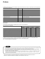
Special Notes
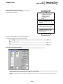
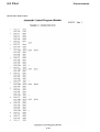
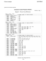
The PC Series models and their compatible software versions are as listed below.
Other models are not supported.
Model
Software version
1.01.014...
1.10.014...
1.11.003...
2.00.XXX...
NB0
O
O
O
O
NBE (24-point and 36-point basic units for NB2)
O
O
O
O
NB (56-point and 90-point basic units for NB1 and NB2)
O
O
O
O
NJE (NJ-CPU-E4)
O
O
O
O
NJ (NJ-CPU-A8, A32, B32)
O
O
O
O
NJH (NJ-CPU-B16)
O
O
O
O
NS (NS series)
O
O
O
O
SPB
x
x
x
O
In addition to the above manuals, the following Fuji Electric FA Components & Systems Co., Ltd. site offers various
manuals and technical documents associated with FLEX-PC and MICREX-SX SPB.
URL http://www.fujielectric.co.jp/fcs/eng/
Notes
1. This manual may not be reproduced in whole or part in any form without prior written approval by the manufacturer.
2. The contents of this manual (including specifications) are subject to change without prior notice.
3. If you find any ambiguous or incorrect descriptions in this manual, please write them down (along with the manual
No. shown on the cover) and contact FUJI.
4. The loader software is subject to version up due to functional improvement, etc. Therefore, an explanation of some
items may not be found in this manual. For details, please check the revision log included in Preface , using the
help function of the loader software.
* Microsoft and Windows are registered trademarks or trademarks of Microsoft Corporation of the U.S.A.
* Pentium is a registered trademark or trademark of Intel Corporation of the U.S.A.
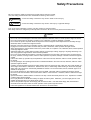
Safety Precautions
Be sure to read the “Safety Precautions” thoroughly before using the module.
Here, the safety precaution items are classified into “Warning” and “Caution.”
Warning : Incorrect handling of the device may result in death or serious injury.
Caution
: Incorrect handling of the device may result in minor injury or physical damage.
Even some items indicated by “Caution” may also result in a serious accident.
Both safety instruction categories provide important information. Be sure to strictly observe these instructions.
Caution
◊ Do not use one found damaged or deformed when unpacked, otherwise, failure or erratic operation might be caused.
◊ Do not shock the product by dropping or tipping it over, otherwise, it might be damaged or troubled.
◊ Do not leave the product in places where it is exposed to direct sunlight or where temperature and humidity are high.
Otherwise, failure or malfunction might be caused.
◊ Keep the connectors free from accumulation of dusts. Otherwise, failure or malfunction might be caused.
◊ Engage the communication cable connector firmly and lock it, otherwise, erratic operation be might caused.
◊ When disengaging the communication cable or the power cable, do not pull the cord, otherwise, failure, erratic operation
or damage might be caused.
◊ Sufficiently make sure of safety before program change, forced output, starting, stopping or anything else during a run.
The wrong operation might break or cause machine problems.
◊ Do not turn off the loader during loader is in operation (accessing to the hard disk or the floppy disk, communicating to
the PLC), otherwise, missing of *data, failure or erratic operation of products, damage or trouble of machines might be
caused.
◊ Perform the version-up operation by the explanation of the user’s manual, otherwise, failure or erratic operation might
be caused.
◊ Use this package in the operating environment of software described in the user’s manual, otherwise, failure or erratic
operation might be caused.
◊ Carefully use the CD-ROM to keep its recording surface free from finger-print mark, stain, flaw, dust, water droplet, etc.,
which might cause failure or malfunction. Remove stain, dust, or other foreign matter sticking on the surface by lightly
wiping with a dry soft cloth or commercially available CD cleaner. Do not use benzene, thinner, antistatic agent or LP
cleaner for this purpose.
◊ Do not write characters or stick adhesive seal on the CD-ROM. Otherwise, failure or malfunction might be caused.
◊ Be sure to insert the CD-ROM or the communication cable in correct direction. Otherwise, failure or malfunction might
be caused.
◊ Operate the loader in stable condition so that it do not drop or other abnormality does not occur. Operation in unstable
condition might cause accidents.
◊ Do not play back the CD-ROM with ordinary CD player for audio system. Otherwise, your ears might get hurt or the
speaker be damaged due to very large sound volume.
◊ Perform the periodic inspection for the floppy disk and the hard disk. If the data inside floppy disk, hard disk and
CD-ROM are in fault status, failure or erratic operation of the system might be caused.
◊ Follow the regulations of industrial wastes when the device is to be discarded.
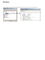
Revision
*Manual No. is shown on the cover.
Printed on
*Manual No.
Revision contents
May 2001
FEH403
First printing (Product version 2.00.XX)
Jun 2001
FEH403a
Second edition (PDF manual for CD Product version 2.1.X.X)
Jan 2002
FEH403b
3rd edition (The Import/Export Function added and the Transfer/Verify
Function changed for products version 2.1.1.0)
Jun 2002
FEH403c
Four edition (The Transfer Function and Export Function changed for
products version 2.1.1.1)
Revision
Check the details on the revision history by selecting [Introduction] in the Help contents and then [Version History].
Contents
Preface
Safety Precautions
Revision
Contents
Page
Section 1 Introduction...................................................................................1-1
1-1 How to Use This Manual ................................................................................................................ 1-1
1-1-1 Organization of this manual .................................................................................................................. 1-1
1-1-2 Terms and symbols used in this manual ............................................................................................... 1-1
1-2 Operating Environment .................................................................................................................. 1-2
1-3 Personal Computer Loader System Configuration .................................................................... 1-3
1-4 Method of Installation .................................................................................................................... 1-4
1-4-1 Personal computer loader software ...................................................................................................... 1-4
1-4-2 Installation procedure ............................................................................................................................ 1-4
1-4-3 Group of programs installed .................................................................................................................. 1-6
1-5 Uninstall .......................................................................................................................................... 1-7
1-6 Starting the Personal Computer Loader ...................................................................................... 1-9
1-7 Screen Configuration ................................................................................................................... 1-10
1-7-1 Screen configuration ........................................................................................................................... 1-10
1-7-2 Window types ...................................................................................................................................... 1-13
Section 2 Offline Operations ........................................................................2-1
2-1 Preparations for Programming ..................................................................................................... 2-1
2-1-1 Opening a new file ................................................................................................................................. 2-1
2-1-2 Menus and tool bars used to edit program ........................................................................................... 2-2
2-1-3 Setting tag entry/display ........................................................................................................................ 2-3
2-2 Programming .................................................................................................................................. 2-6
2-2-1 Writing contacts and outputs ................................................................................................................. 2-6
2-2-2 Writing a returning ............................................................................................................................... 2-18
2-2-3 Writing Inverse instruction ................................................................................................................... 2-20
2-2-4 Writing ON-delay timer ........................................................................................................................ 2-21
2-2-5 Writing Up counter ............................................................................................................................... 2-22
2-2-6 Writing Data Transfer (MOV) instruction .............................................................................................. 2-25
2-2-7 Instruction input notes ......................................................................................................................... 2-28
2-3 Program Modification .................................................................................................................. 2-29
2-3-1 Changing instructions/addresses ........................................................................................................ 2-29
2-3-2 Addition of lines/instructions ............................................................................................................... 2-31
2-3-3 Changing a tag .................................................................................................................................... 2-44
2-4 Line Copy/Insert/Delete ............................................................................................................... 2-46
2-4-1 Selecting a line block ........................................................................................................................... 2-46
2-4-2 Copying and pasting a line block ........................................................................................................ 2-48
2-4-3 Cutting and pasting line block (move) ................................................................................................. 2-49
2-4-4 Deleting a line block ............................................................................................................................ 2-50
2-5 Tag Editor ...................................................................................................................................... 2-51
2-5-1 Outline of Tag Window ......................................................................................................................... 2-51
2-5-2 Operation with Tag Editor .................................................................................................................... 2-52
Contents
2-5-3 Search and replacement using the tag editor ..................................................................................... 2-54
2-5-4 Tag editor filter ..................................................................................................................................... 2-54
2-5-5 Reading a tag text file .......................................................................................................................... 2-54
2-6 Line Comment Edit ....................................................................................................................... 2-57
2-7 Find/Replace Functions ............................................................................................................... 2-59
2-7-1 [Address/Tag] Find function ................................................................................................................ 2-59
2-7-2 [Address/Tag] Replace function ......................................................................................................... 2-60
2-7-3 Line Search function ........................................................................................................................... 2-62
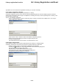
2-8 Library Registration and Read .................................................................................................... 2-63
2-8-1 Library registration function ................................................................................................................. 2-63
2-8-2 Library read function ........................................................................................................................... 2-63
2-9 Function block .............................................................................................................................. 2-65
2-9-1 Outline of function block (User Macrocommand) ................................................................................ 2-65
2-9-2 Function block library (User Macrocommand) .................................................................................... 2-66
2-10 Parameter Setting ....................................................................................................................... 2-69
2-10-1 Displaying parameter setting dialog box ........................................................................................... 2-69
2-10-2 Operating parameter setting dialog box ............................................................................................ 2-70
2-11 Program Saving and Opening ................................................................................................... 2-75
2-11-1 Saving a program .............................................................................................................................. 2-75
2-11-2 Opening a program ........................................................................................................................... 2-77
2-12 Import/Export .............................................................................................................................. 2-78
2-12-1 Import ................................................................................................................................................ 2-78
2-12-2 Expotr ................................................................................................................................................ 2-79
2-12-3 Property ............................................................................................................................................. 2-81
2-13 Mnemonic Instructions .............................................................................................................. 2-82
2-13-1 Outline of mnemonic edit windows ................................................................................................... 2-82
2-13-2 Editing a mnemonic instruction ......................................................................................................... 2-83
Section 3 Online Operations .......................................................................3-1
3-1 Preparation for Online Connection and Outline of Online Operations .................................... 3-1
3-1-1 Hardware system configuration ............................................................................................................. 3-1
3-1-2 Setting communication parameters for the loader ................................................................................ 3-2
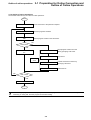
3-1-3 Outline of online operations .................................................................................................................. 3-3
3-2 Online Connection ......................................................................................................................... 3-4
3-3 Save PC Content to File ................................................................................................................. 3-6
3-3-1 Save PC program .................................................................................................................................. 3-6
3-3-2 Saving PC data ...................................................................................................................................... 3-7
3-4 Transfer (Verify) Contents of File to the PC ................................................................................. 3-8
3-4-1 Transfer contents of program file to the PC .......................................................................................... 3-8
3-4-2 Transfer contents of data file to the PC ............................................................................................... 3-11
3-4-3 Transfer contents of parameter file to the PC ..................................................................................... 3-13
3-4-4 Comparing file contents with PC contents .......................................................................................... 3-14
3-5 Start/Stop the PC .......................................................................................................................... 3-15
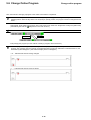
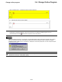
3-6 Change Online Program .............................................................................................................. 3-16
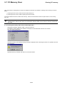
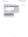
3-7 PC Memory Clear .......................................................................................................................... 3-18
3-7-1 Clearing PC memory with online window kept open .......................................................................... 3-18
3-7-2 Clearing PC memory without opening online window ........................................................................ 3-19
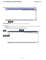
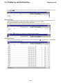
3-8 Displaying and Setting Data ........................................................................................................ 3-20
3-8-1 Displaying data .................................................................................................................................... 3-20
3-8-2 Setting data ......................................................................................................................................... 3-23
Contents
3-9 PC Diagnosis ................................................................................................................................ 3-24
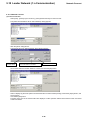
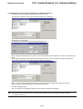
3-10 Loader Network (1:n Communication) ..................................................................................... 3-25
3-10-1 Network Connect ............................................................................................................................... 3-26
3-10-2 Changing or releasing the destination of network connection ......................................................... 3-27
3-11 Sampling Trace (Recording of Data History) ........................................................................... 3-28
3-11-1 Setting sampling trace ....................................................................................................................... 3-30
3-11-2 Sampling trace execution .................................................................................................................. 3-32
3-11-3 Display of sampling trace .................................................................................................................. 3-34
3-11-4 Saving sampling trace data ............................................................................................................... 3-35
3-11-5 Sampling trace cancel all .................................................................................................................. 3-36
3-12 Status Latch (Recording Data at a Point of Time) .................................................................. 3-37
3-12-1 Outline of function ............................................................................................................................. 3-37
3-12-2 Creating a program ........................................................................................................................... 3-37
3-12-3 Status latch registration ..................................................................................................................... 3-39
3-12-4 Status latch execution ....................................................................................................................... 3-40
3-12-5 Status latch result display ................................................................................................................. 3-41
3-12-6 Saving status latch data .................................................................................................................... 3-42
3-12-7 Status latch cancel all ....................................................................................................................... 3-42
Section 4 Print Function ...............................................................................4-1
4-1 Outline of Print Function ............................................................................................................... 4-1
4-1-1 Page setup ............................................................................................................................................. 4-1
4-1-2 Print setup ............................................................................................................................................. 4-2
4-1-3 Print Preview ......................................................................................................................................... 4-8
4-1-4 Printer Setup ......................................................................................................................................... 4-8
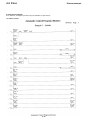
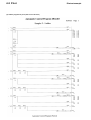
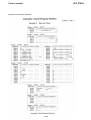
4-2 Print ................................................................................................................................................. 4-9
4-2-1 Execution of print operation .................................................................................................................. 4-9
4-2-2 Printout example ................................................................................................................................. 4-10
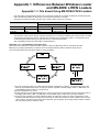
Appendix 1 Differences Between Windows Loader and
MS-DOS/ LITE/N Loaders ..................................................... App.1-1
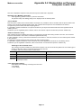
Appendix 1-1 File Saved Using MS-DOS/LITE/N Loaders ........................................................ App.1-1
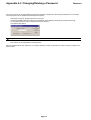
Appendix 1-1-1 Compatibility of Program Files ...................................................................................... App.1-1
Appendix 1-1-2 Compatibility of Comment Files .................................................................................... App.1-2
Appendix 1-2 Functions of Windows Loader ............................................................................. App.1-4
Appendix 2 Environment Setting ......................................................... App.2-1
Appendix 2-1 Environment Options ........................................................................................... App.2-1
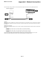
Appendix 3 Modem Connection ........................................................... App.3-1
Appendix 3-1 Preparation of Modem on PC Side ...................................................................... App.3-2
Appendix 3-1-1 Using an RS-232C module (NB-RS1/NJ-RS2/NS-RS1) ............................................... App.3-2
Appendix 3-1-2 Using the RS-232C port of CPU (NJ-CPU-B16/NS-CPU-B32/NS-CPU-B64) .............. App.3-3
Appendix 3-1-3 Preparations for Modem Connection on PC Side .......................................................... App.3-6
Appendix 3-2 Manipulation on Personal Computer Loader Side ............................................ App.3-7
Appendix 3-2-1 Modem connection ......................................................................................................... App.3-7
Appendix 3-2-2 Modem Disconnection ................................................................................................... App.3-9
Appendix 3-3 RS-232C Cable Connection ............................................................................... App.3-10
Contents
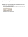
Appendix 4 Password ...........................................................................App.4-1
Appendix 4-1 Setting a New Password ...................................................................................... App.4-2
Appendix 4-2 Opening a Program with Password .................................................................... App.4-3
Appendix 4-3 Changing/Deleting a Password ........................................................................... App.4-4
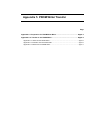
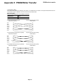
Appendix 5 PROM Writer Transfer ........................................................ App.5-1
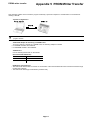
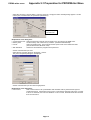
Appendix 5-1 Preparation for PROM Writer Move ...................................................................... App.5-3
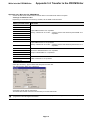
Appendix 5-2 Transfer to the PROM Writer ................................................................................ App.5-5
Appendix 5-2-1 Write into the PROM Writer ............................................................................................ App.5-5
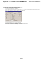
Appendix 5-2-2 Collation with the PROM Writer ..................................................................................... App.5-6
Appendix 5-2-3 Read from the PROM Writer .......................................................................................... App.5-7
Appendix 6 Shortcut Key List ..............................................................App.6-1
Appendix 6-1 Shortcut Key List .................................................................................................. App.6-1
Section 1 Introduction
Page
1-1 How to Use This Manual ............................................................................................. 1-1
1-1-1 Organization of this manual .................................................................................................. 1-1
1-1-2 Terms and symbols used in this manual ............................................................................... 1-1
1-2 Operating Environment .............................................................................................. 1-2
1-3 Personal Computer Loader System Configuration.................................................. 1-3
1-4 Method of Installation ................................................................................................. 1-4
1-4-1 Personal computer loader software ...................................................................................... 1-4
1-4-2 Installation procedure ............................................................................................................ 1-4
1-4-3 Group of programs installed .................................................................................................. 1-6
1-5 Uninstall ....................................................................................................................... 1-7
1-6 Starting the Personal Computer Loader ................................................................... 1-9
1-7 Screen Configuration ............................................................................................... 1-10
1-7-1 Screen configuration ........................................................................................................... 1-10
1-7-2 Window types ...................................................................................................................... 1-13
Organization of this manual
Section 1 Introduction
1-1 How to Use This Manual
The FLEX PC Programmer is a Windows-based programming tool for the FLEX-N Series PCs. This software has a number
of offline and online functions, including program edit and print functions.
This manual describes the basic operations that are most frequently used. For operations not described in this manual and
detailed contents of the operations, refer to the FLEX PC Programmer Help. The Help also contains the latest information
about the use of the software functions, etc.
This manual does not describe the basic operations of Windows (maximization and minimization of the screen, use of the
scroll bar, etc.). For the basic operations of Windows, refer to the appropriate manual of Windows.
1-1-1 Organization of this manual
Section 1 gives the outline of the software and describes the operating environment and installation of the software and
the devices that are necessary for connection between the PC and the personal computer.
Section 2 describes programming, program editing, program saving, etc. performed offline with the PC.
Section 3 describes program/data monitoring, editing, etc. performed online with the PC.
The Appendixes provide supplementary information about such subjects as the compatibility with data created by a DOSbased loader.
1-1-2 Terms and symbols used in this manual
In this manual, the following terms and symbols are used.
On mouse operation
Click ........................ Pushing the right or left button of the mouse once and releasing it immediately.
Double-click ............ Clicking the mouse twice quickly.
Drag ........................ Moving the mouse cursor with the left button of the mouse kept pushed.
On keyboard operation
A few examples of keyboard operations are given below. Basically, the keyboard operations are the same as those for
Windows.
<SHIFT> key ........... The key with letters {SHIFT} written on keytop.
<SHIFT> + <C> ...... Pushing the <C> key with the <SHIFT> key kept pushed.
[File] – [New] .......... Selecting item [File] displayed at the top of the screen first, then selecting item [New] from the
list that appears on the screen.
On text description
• Used for enumeration of items.
◊ Used to indicate a particular operation to be performed.
1-1
1-2 Operating Environment
Operating
The environment required for installing and operating the software is as follows.
• A personal computer with following English version O/S.
(The software does not operate on Microsoft Windows 3.1.)
• Microsoft Windows 95
• Microsoft Windows 98
• Microsoft Windows Millennium Edition
• Microsoft Windows NT Workstation 4.0 (Service Pack 6 or later)
• Microsoft Windows 2000 Professional
If the operating system is not upgraded to the latest version by a service package or other, the software may not
run normally.
• RAM of 32MB or more. For comfortable running, 64MB or a greater capacity is recommended.
• 10MB or a greater capacity on the hard disk. For the operating system to run stably, about 100MB is
recommended.
• A pointing device, such as the mouse or track ball.
• A display device of 800 x 600 dots or more.
• A CD drive.
1-2
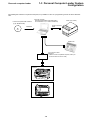
1-3 Personal Computer Loader System
Configuration
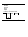
Personal computer loader
By installing the software on a personal computer, it is possible to use it as a programming tool for the FLEX-N Series
PCs.
Personal computer loader software
(Type: NN4NWN-SB)
Personal computer
(Windows 95/98, Millennium Edition (ME),
NT Workstation 4.0, or 2000 Professional)
Printer (any maker)
Printer connection
cable
Installation
CD
RS-232C
ROM writer
PC connection cable
NN-CNV3
(cable for PC/AT-compatible computer, with 9-pin
D-subconnector on the PC side)
FLEX-N
MICREX-SX SPB
1-3
1-4 Method of Installation
Installation
1-4-1 Personal computer loader software
Program loader software package is supplied in the form of CD.
The installation CD includes the installation program which automatically executes operations necessary for installation as
well as the registration of icons.
If you have already installed a beta edition of this software package, uninstall it first, then install the personal computer
loader software. Do not overwrite the personal computer loader. If the personal computer loader software is installed
without uninstalling the Windows-based personal computer loader, the software may not operate properly. For the method
of uninstallation, refer to “1-5 Uninstall.”
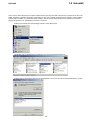
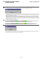
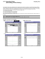
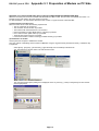
1-4-2 Installation procedure
◊ Before installing the personal computer loader software, close all the Windows programs that are open.
◊ Insert the CD into CD drive.
CD automatically runs, and item selection dialog box appears.
◊ Left-click the [PC Programmer Setup].
{Install Shield Wizard Preparing} working box appears on the screen. Then, {Welcome} dialog box appears.
◊ Left-click the [Next >] button.
{Software license Agreement} dialog box appears.
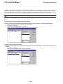
◊ If you agree with those contents, left-click the [Yes] button.
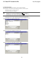
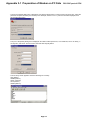
The {Choose Destination Location} dialog box appears.
◊ When you want to change the default directory for installation (C:\Program Files\FLEX-PC Programmer[E]), leftclick the [Browse...] button, designate the desired directory for installation in the {Choose Directory} dialog box, and
left-click the [OK] button.
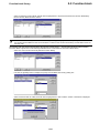
◊ The {Select Program Folder} dialog box is displayed. To change the default folder of the “FLEX-PC Programmer,”
enter an appropriate program folder name in the text box. Left-click the [Next >] button.
◊ The {Start Copying Files} dialog box is displayed. Confirm the content of the display and left-click the [Next >]
button.
The copying of files starts.
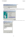
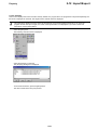
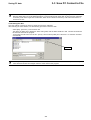
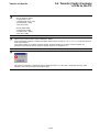
◊ When setup completes, the following screen appears.
Turn on the check box of the next execution button and left-click the [Finish] button.
Turn on the [Yes, Launch the program file] check box and left-click the [Finish] button to start up the PC loader as
follows:
1-4
1-4 Method of Installation
Installation
<PC loader starting screen>
1-5
1-4 Method of Installation
Installation
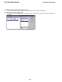
1-4-3 Group of programs installed
When the installation is completed, the following icons are registered in the program group.
• FLEX-PC Programmer
This is the loader software.
• FLEX-PC Programmer Help
This is a file which contains the latest information that is helpful in using the loader software. This file can also be
used as a reference. It is recommended that the user read through the file.
1-6
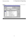
1-5 Uninstall
Uninstall
This is used to delete the personal computer loader software from the hard disk of the personal computer. Even when the
loader software is uninstalled, all the files created by the user, such as ladder program files and tag files, remain installed
together with the folders. To uninstall the loader software, execute the Uninstall program that is provided as a standard
program of Windows. The uninstallation procedure is as follows.
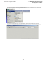
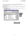
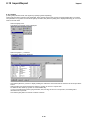
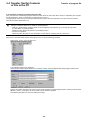
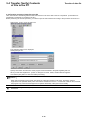
◊ Select [Control Panel] from the [Settings] submenu of the [Start] menu.
◊ Left-double-click the [Add/Remove Programs] icon in the {Control Panel} dialog box.
◊ Select [FLEX-PC Programmer [E]] from the list displayed on the screen and left-click the [Add/Remove...] button.
1-7
1-5 Uninstall
Uninstall
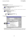
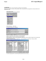
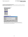
◊ The {Confirm File Deletion} dialog box is displayed. Left-click the [Yes] button.
◊ The uninstall operation is started.
During this operation, the {Remove Shared File?} dialog box may be displayed as shown below. In this case, if
you remove the shared file, it can happen that some programs do not function and in the worst case, Windows
might fail to work. Normally, select either [No] or [No to All.]
◊ When the message “Uninstall Completed,” left-click the [OK] button.
◊ The {Add/Remove Programs Properties} dialog box is displayed again. Left-click the [Cancel] button to close the
dialog box. Now the uninstall operation is completed.
1-8
1-6 Starting the Personal
Computer Loader
Personal computer loader
◊ First, select [FLEX PC Programmer [E]] from the [Programs] submenu of the [Start] menu. Then, select [FLEX
PC Programmer] from the menu that appears on the screen.
◊ The personal computer loader starts. From this screen, the user can perform desired offline and online
operations. For the methods of offline and online operations, refer to “Section 2” and the subsequent sections.
1-9
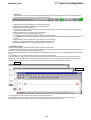
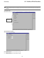
1-7 Screen Configuration
Screen configuration
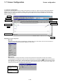
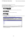
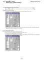
1-7-1 Screen configuration
The personal computer loader screen contains various buttons, tool bars, etc. which are used to edit programs/data or
display the current condition of a specific operation. Here, those components which are displayed on the screen are
explained taking the offline edit screen as an example. Open the offline screen to enter the Edit mode, and the screen
display becomes as follows.
Menu bar
Main tool bar
Instruction group tab
Line edit buttons
Instruction buttons
Program window
Ladder edit tool bar
Cursor
Display selection tab
Status bar
Explanation of each component
• Menu bar
The menu bar contains items for operating the software. When any of the items in the menu is left-clicked, a
detailed command list associated with it appears on the screen.
• Main tool bar
The main tool bar contains tool buttons, each of which produces the same effect as when the command
[New] button executes the
corresponding to it is selected from the menu bar and executed. For example, the
same operation as when [File] – [New] is selected from the menu bar and executed. To see the meaning of each
of the tool buttons, move the cursor to the tool button and left-click the button, and a window which explains the
function of the tool button is displayed as shown below.
Move the cursor to this
tool button and left-click
the button.
A window which explains
the function of the button
is displayed.
1-10
1-7 Screen Configuration
Screen configuration
• Ladder edit tool bar
This bar appears when the window is set in the [Edit] mode. It disappears when the window is set in the [Monitor]
mode. To switch between the [Edit] mode and the [Monitor] mode, left-click the
[Edit] button. This bar contains
tools which are necessary to edit programs.
[Monitor] mode
[Edit] mode
Ladder edit tool bar
• Line edit buttons
Buttons for editing lines, such as [Insert Line] and [Delete Line], are arranged here.
• Instruction group tab
This tab is used to select the instruction group to be used. When any instruction group is selected and leftclicked, the associated instruction buttons change as illustrated below.
When [Contact] is selected
When [Output] is selected
To display a tab which is hidden in the right or left margin of the screen, left-click the Scroll Left or Scroll Right
button.
• Instruction buttons
These buttons are used to select ladder program instructions. To see the meaning of each of the instruction
buttons, move the cursor to the instruction button and left-click the button, and a window which explains the
meaning of the instruction button is displayed as shown below.
Move the cursor to this
button and left-click the
button.
A window which explains
the meaning of the
button is displayed.
1-11
1-7 Screen Configuration
Screen configuration
• Cursor
The cursor indicates the currently selected item to be edited (in the example given below, [Normally Open
Contact] of address <X0000>). It is displayed as an instruction selection frame when an instruction on a ladder
line is left-clicked. It is also possible to move the cursor using the Arrow keys on the keyboard.
The cursor is displayed only in the [Edit] mode.
• Program window
The program window is the entire screen area in which the ladder program that is being edited (or monitored) is
displayed.
• Display selection tabs
To monitor/edit a ladder program, left-click the [File 1] tab.
To monitor/set data, left-click the [Data 1] tab.
1-12
1-7 Screen Configuration
Windows types
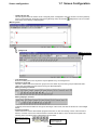
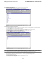
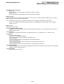
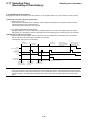
• Status bar
The status bar indicates the mode and operating condition of the window that is currently being displayed, the
help message for the tool bar button currently selected, etc.
1)
2)
3)
4)
5) 6)
7)
8)
9)
10)
1) Displays the help message for the tool bar button selected.
2) Indicates online display, offline display, or modem display.
3) Indicates the PC model selected.
4) Indicates the number of program steps currently used and the total number of program steps that can be used
with the PC model selected.
5) Online connection to PC at the local or other station.
6) Indicates the current mode ([Edit] or [Monitor]).
7) In the [Edit] mode, indicates a Page/Line number currently selected.
In the [Monitor] mode, indicates the line number at the top of the ladder diagram currently being displayed on the
screen.
8) Step number of the first instruction of the line at the cursor position.
9) Match or mismatch between PC RAM and flash memory (for SPB).
10) Indicates whether the PC is in [Running] or [stop] of operation.
1-7-2 Window types
There are two types of windows-the offline window and the online window.
The offline window is used when monitoring/editing a ladder program which has been saved in the personal computer. It is
possible to open more than one offline window at a time.
The online window is used when monitoring/editing a ladder program in the PC. Only one online window can be opened at
a time.
It is possible to open an offline window and an online window at the same time.
The type (offline or online) of the window being opened is displayed on the title bar at the top of the window. When any
point of the window being opened is left-clicked, the title bar changes in color. This indicates that the window has been
selected as the one to be operated on. This window that has been selected is called an active window.
File name
Active window
Any other window can be made “active” simply by clicking any point of it.
In the [Edit] mode, it is possible to copy a ladder program from one window to another on a line-by-line basis.
For the offline operations, refer to “Section 2.” For the online operations, refer to “Section 3.”
1-13
Section 2 Offline Operations
Page
2-1 Preparations for Programming .................................................................................. 2-1
2-1-1 Opening a new file ................................................................................................................ 2-1
2-1-2 Menus and tool bars used to edit program ............................................................................ 2-2
2-1-3 Setting tag entry/display ........................................................................................................ 2-3
(1) Setting program editor ............................................................................................................................ 2-3
2-2 Programming ............................................................................................................... 2-6
2-2-1 Writing contacts and outputs ................................................................................................. 2-6
(1) Writing a series line ................................................................................................................................. 2-6
(2) Writing branches ................................................................................................................................... 2-10
(3) Writing branch outputs .......................................................................................................................... 2-15
2-2-2 Writing a returning ............................................................................................................... 2-18
(1) Writing returning (output) ...................................................................................................................... 2-18
(2) Writing returning (input) ........................................................................................................................ 2-18
2-2-3 Writing Inverse instruction ................................................................................................... 2-20
2-2-4 Writing ON-delay timer ........................................................................................................ 2-21
2-2-5 Writing Up counter .............................................................................................................. 2-22
2-2-6 Writing Data Transfer (MOV) instruction ............................................................................. 2-25
2-2-7 Instruction input notes ........................................................................................................ 2-28
(1) JUMP and JEND instructions .............................................................................................................. 2-28
(2) Master Control Set (MC) and Master Control Reset (MCR) instructions ............................................. 2-28
(3) Constant input ...................................................................................................................................... 2-28
2-3 Program Modification ............................................................................................... 2-29
2-3-1 Changing instructions/addresses ........................................................................................ 2-29
2-3-2 Addition of lines/instructions ............................................................................................... 2-31
(1) Inserting a new line ............................................................................................................................... 2-31
(2) Inserting a new contact ......................................................................................................................... 2-32
(3) Editing connecting lines ........................................................................................................................ 2-38
(4) Compressing the program (removing blanks) ....................................................................................... 2-40
(5) Inserting a line (inserting a blank line) .................................................................................................. 2-40
(6) Deleting a contact or coil ....................................................................................................................... 2-41
(7) Merging lines ......................................................................................................................................... 2-43
(8) Dividing a line ....................................................................................................................................... 2-44
2-3-3 Changing a tag .................................................................................................................... 2-44
2-4 Line Copy/Insert/Delete ............................................................................................ 2-46
2-4-1 Selecting a line block .......................................................................................................... 2-46
(1) Selecting a single line block .................................................................................................................. 2-46
(2) Selecting two or more line blocks ......................................................................................................... 2-47
2-4-2 Copying and pasting a line block ........................................................................................ 2-48
(1) Copying a line block .............................................................................................................................. 2-48
(2) Pasting the copy of line block ................................................................................................................ 2-48
2-4-3 Cutting and pasting line block (move) ................................................................................. 2-49
(1) Cutting a line block ................................................................................................................................ 2-49
(2) Pasting the cut line block ...................................................................................................................... 2-49
2-4-4 Deleting a line block ............................................................................................................ 2-50
(1) Deleting a single line block ................................................................................................................... 2-50
(2) Deleting two or more line blocks at a time ............................................................................................ 2-50
2-5 Tag Editor ................................................................................................................... 2-51
2-5-1 Outline of Tag Window ........................................................................................................ 2-51
2-5-2 Operation with Tag Editor .................................................................................................... 2-52
(1) Configuration of Tag Editor .................................................................................................................... 2-52
(2) Inserting a new tag ............................................................................................................................... 2-53
2-5-3 Search and replacement using the tag editor ..................................................................... 2-54
(1) Search section ..................................................................................................................................... 2-54
2-5-4 Tag editor filter ..................................................................................................................... 2-54
(1) Configuration of the filter section ......................................................................................................... 2-54
2-5-5 Reading a tag text file ......................................................................................................... 2-54
(1) Text file format ....................................................................................................................................... 2-54
(2) Importing text file .................................................................................................................................. 2-55
(3) Display of tag after inporting text file ..................................................................................................... 2-56
2-6 Line Comment Edit ................................................................................................... 2-57
2-7 Find/Replace Functions ........................................................................................... 2-59
2-7-1 [Address/Tag] Find function ............................................................................................... 2-59
(1) First retrieval ......................................................................................................................................... 2-59
(2) Succeeding search ............................................................................................................................... 2-60
2-7-2 [Address/Tag] Replace function ......................................................................................... 2-60
2-7-3 Line Search function ........................................................................................................... 2-62
2-8 Library Registration and Read................................................................................. 2-63
2-8-1 Library registration function ................................................................................................. 2-63
2-8-2 Library read function ........................................................................................................... 2-63
2-9 Function block .......................................................................................................... 2-65
2-9-1 Outline of function block (User Macrocommand) ................................................................ 2-65
(1) Describing a function block and displaying function block information ................................................ 2-65
2-9-2 Function block (User Macrocommand) library .................................................................... 2-66
(1) Saving into the function block library (from the function block execution section
to the function block library) .................................................................................................................. 2-66
(2) Adding or deleting a function block ....................................................................................................... 2-66
(3) Collating with the function block library (from the function block library
to the function block execution section) ................................................................................................ 2-67
(4) Deletion from the function block execution section ............................................................................... 2-68
(5) Deletion from the function block library ................................................................................................. 2-68
2-10 Parameter Setting ................................................................................................... 2-69
2-10-1 Displaying parameter setting dialog box ........................................................................... 2-69
2-10-2 Operating parameter setting dialog box ............................................................................ 2-70
(1) Processor operation definition dialog box ............................................................................................. 2-70
(2) Area setting dialog box ......................................................................................................................... 2-71
(3) Input filter setting dialog box ................................................................................................................. 2-71
(4) High-speed counter setting dialog box .................................................................................................. 2-72
(5) I/O configuration setting dialog box ....................................................................................................... 2-72
(6) Other function setting dialog box .......................................................................................................... 2-73
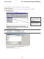
2-11 Program Saving and Opening ............................................................................... 2-75
2-11-1 Saving a program .............................................................................................................. 2-75
(1) Saving a program into a file .................................................................................................................. 2-75
(2) File contents when a program is saved ................................................................................................. 2-76
2-11-2 Opening a program ........................................................................................................... 2-77
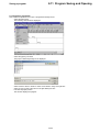
2-12 Import/Export .......................................................................................................... 2-78
2-12-1 Import ................................................................................................................................ 2-78
2-12-2 Export ............................................................................................................................... 2-79
2-12-3 Property ............................................................................................................................ 2-81
2-13 Mnemonic Instructions ........................................................................................... 2-82
2-13-1 Outline of mnemonic edit windows ................................................................................... 2-82
(1) Displaying edit line instructions ............................................................................................................. 2-82
(2) Displaying an instruction list .................................................................................................................. 2-83
2-13-2 Editing a mnemonic instruction ......................................................................................... 2-83
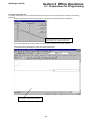
Opening a new file
Section 2 Offline Operations
2-1 Preparations for Programming
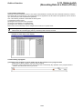
2-1-1 Opening a new file
To create a new program, start the personal computer loader and open a new file (program window) by the following
operations.
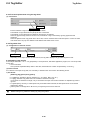
◊ Select the [New] command from the [File] menu. The {Select PC Model} dialog box is displayed.
The programming instructions that can be used
and the contents of the system definition are
determined by the PC model selected here.
* The models displayed in the above dialog box depend on the version of the loader software.
◊ After selecting the appropriate PC model, left-click the [OK] button.
A {program window} is displayed in the main window of the loader.
This is the program window. You can
start writing a program in this window.
2-1
2-1 Preparations for Programming
Menus and tool bars
2-1-2 Menus and tool bars used to edit program
The commands in the menus and the tool bars (buttons) that are mainly used when editing a program are explained below.
All the functions of the tool bars are included in the menus.
Command name
(Button name)
Button Menu
Explanation (use)
New...
File
Creates a new program file.
Open...
File
Opens a program file which has already been created.
Online
File
Opens an online PC program.
Save
File
Saves a program file. If a program file of the same file name already
exists, it is overwritten.
Print...
File
Prints an active program file.
Print Preview
File
Permits the result of printout to be checked on the screen.
Find
Search
Searches for any specified address and tag name.
Jump to specified line
Search
Displays a line with a specified number.
Edit Mode
Edit
Sets a program ready to be edited.
Undo Editing
Edit
Cancels the last operation performed and restores the original condition.
Redo Editing
Edit
Reverses the operation that has been canceled by the [Undo] command.
Tag Editor
Auxiliary
Starts {Tag Editor} to permit tags to be edited.
Cut
Edit
Copies any selected line block to the clipboard. The selected line block is
deleted.
Copy
Edit
Copies any selected line block to the clipboard.
Paste
Edit
Pastes a line block that has been copied to the clipboard to a specified
location.
Run / Stop
PC functions Starts or stops the online-connected processor.
Insert Line
Edit
Inserts a line block starting point which is necessary when preparing a
new line block.
Insert Line below
cursor
Edit
Inserts a start point below to create a new line block.
Insert
/ Modify Comment...
Edit
Inserts a new line comment or modifies an existing line comment. A line
comment is used to explain a particular line of a program.
Delete Line
Edit
Deletes a selected line block.
Display line as
Instruction List
Edit
Displays a selected line by instructions.
Download changes
to PC
Edit
Downloads ladder lines changed in an online window to a PC attched.
2-2
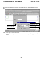
Setting tag entry/display
2-1 Preparations for Programming
2-1-3 Setting tag entry/display
During program editing, it is possible to enter tags while writing instructions in the program. It is also possible to display the
tag entries on the program. The methods of setting tag entry/display are explained below.
The tag is a label (name) which is in one-to-one correspondence with an address. It corresponds to a comment in
the MS-DOS-based loader.
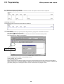
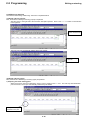
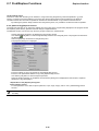
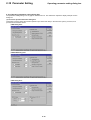
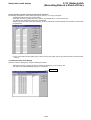
(1) Setting program editor
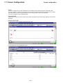
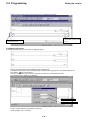
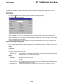
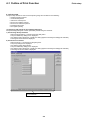
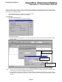
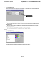
◊ Select the [Environment...] command from the [Option] menu.
The {Environment Options} dialog box is displayed.
◊ Left-click the [Editor Options] tab.
The items to set to edit and display the program are displayed.
[Editor Options] tab
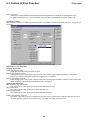
1) Setting the edit options
[Both Address and Tag] option button
Displays an address and a tag above the instruction symbol.
[Tag] option button
Displays only a tag above the instruction symbol. (Note, however, that when no tag has been set for the instruction
address, the instruction address is displayed.)
[Address] option button
Displays only an address above the instruction symbol.
2-3
2-1 Preparations for Programming
Menus and tool bars
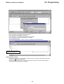
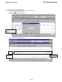
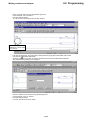
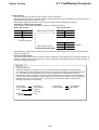
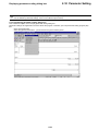
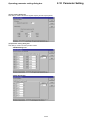
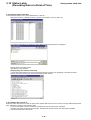
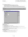
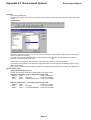
2) Setting automatic tag entry
When the [Auto Documentation] box is checked, the {Tag Editor} dialog box shown below is displayed during program
editing.
The tag name must not exceed 16
characters in length. Note 1)
Displayed when the [OK]
button is left-clicked after
an address is entered.
The description must not exceed
50 characters in length. Note 2)
Note 1: In a tag name, the comma (,) cannot be used.
2: In a description, the comma (,) cannot be used. If a comma is included in the description, it is automatically
deleted when the description is added to the data base. Note that the description is not displayed on a ladder
program.
2-4
Setting tag entry/display
2-1 Preparations for Programming
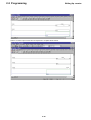
<Tag Editor>
There are two methods of entering a tag name. One is using the {Tag Editor} dialog box described above, and the other is
using [Tag Editor].
For the method of using [Tag Editor], refer to “2-5 Tag Edit.”
2-5
2-2 Programming
Writing contacts and outputs
2-2-1 Writing contacts and outputs
Here, the method of preparing a line which combines contacts and outputs as shown below is explained.
(1) Writing a series line
The method of writing a series line shown below is explained.
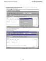
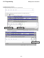
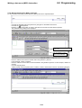
1) Writing contacts
◊ Left-click the [Common] or [Contact] tab of the [Instruction group] tab on the ladder edit tool bar.
[Examine On] button.
◊ Left-click the
◊ Move the cursor to the position in which to describe an instruction and left-click that position.
The {Address Entry} dialog box is displayed.
Move the cursor to this
position and left-click it.
◊ Enter the address of the contact in the [Address] text box.
In this example, <X0> is entered.
◊ Left-click the [OK] button.
When in the {Environment Options} dialog box the [Auto Documentation] box has been checked, the {Tag Editor}
dialog box as shown in the following diagram is displayed. When the [Auto Document] box has been unchecked, the
{Tag Editor} dialog box is not displayed and the contact is described in the program window.
2-6
2-2 Programming
Writing contacts and outputs
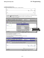
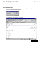
◊ Enter a tag name in the [Tag] text box as required.
In this example, <Start Switch> is entered.
◊ Enter a description in the [Description] text box as required.
In this example, <Push button Switch Blue> is entered.
◊ Left-click the [OK] button.
The normally open contact, address, and tag are displayed as illustrated below.
Normally open contact, address,
and tag are displayed here.
2) Writing series contacts
◊ Left-click the [Common] or [Contact] tab of the [Instruction group] tab on the ladder edit tool bar.
◊ Left-click the
[Examine Off] button.
◊ Move the cursor to the position in which to describe an instruction and left-click that position.
The {Address Entry} dialog box is displayed.
2-7
2-2 Programming
Writing contacts and outputs
Move the cursor to this
position and left-click it.
◊ Enter the address of the contact in the [Address] text box.
In this example, <X1> is entered.
◊ Left-click the [OK] button.
As shown below, the normally closed contact is connected in series to the normally open contact. Note that when in
the {Environment Options} dialog box the [Auto Documentation] box has been checked, the {Tag Editor} dialog box
is displayed. The explanation about this shall be omitted here.
◊ In the same way as described above, write normally open contacts “X0002” and “X0003” and normally closed
contact “X0004” as shown in the following diagram.
2-8
2-2 Programming
Writing contacts and outputs
3) Writing outputs
◊ Left-click the [Common] or [Contact] tab of the [Instruction group] tab on the ladder edit tool bar.
◊ Left-click the
[Output] button.
◊ Move the cursor to the position in which to describe an instruction and left-click that position.
The {Address Entry} dialog box is displayed.
Move the cursor to this
position and left-click it.
◊ Enter the address of the output in the [Address] text box.
In this example, <Y20> is entered.
◊ Left-click the [OK] button.
As shown below, the output is connected in series to the normally closed contact.
◊ After creating a line, shift the cursor from the line under edit.
This converts and determines the line.
About conversion:
When the cursor is shifted from the ladder line under edit, one line is converted. This conversion changes the
ladder line into a mnemonic word. If the ladder line does not permit conversion into a mnemonic word, the cursor
cannot be shifted from the line under edit. Correct the erroneous ladder line into one that can be converted. If a
new line is inserted during online edit, “E” is displayed at the bus. Once the line has been determined by
conversion, “E” disappears from the bus.
2-9
2-2 Programming
Writing contacts and outputs
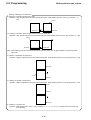
(2) Writing branches
Here, the method of writing a branch of a line shown below is explained.
Branch to single contact
Branch to multiple contacts
1) Writing branch to single contact
◊ Shift the cursor to the contact (X0000) at the instruction description position. While holding down the <Ctrl> key,
press the <↓> key to draw a vertical line.
◊ Left-click the [Common] or [Branch] tab of the [Instruction group] tab on the ladder edit tool bar.
◊ Left-click the
[Examine On] button.
◊ Move the cursor to the position in which to describe an instruction and left-click that position. (A green instruction
selection frame is displayed.)
The {Address Entry} dialog box is displayed.
Move the cursor to this
position and left-click it.
◊ Enter the address of the branch in the [Address] text box.
In this example, <X5> is entered.
2-10
2-2 Programming
Writing contacts and outputs
◊ Left-click the [OK] button.
An Examine On is connected to the contact in series.
2) Writing branch to multiple contacts
<Drawing a downward vertical connection line>
◊ Shift the cursor to the contact (X0001) at the top left of a parallel contact description position. While holding down
the <Ctrl> key, press the <↓> key to draw a vertical line.
2-11
2-2 Programming
Writing contacts and outputs
<Drawing a horizontal connection line>
◊ While holding down the <Ctrl> key, press the <→> key to draw a horizontal line.
<Drawing an upward vertical connection line>
◊ While holding down the <Ctrl> key, press the <↑> key to draw a vertical line to the upper level.
2-12
2-2 Programming
Writing contacts and outputs
<Changing horizontal connection line to contact>
◊ Left-click the [Common] or the Contact tab in the [Instruction group] tabs on the ladder edit tool bar.
◊ Left-click the
[Examine On] button.
◊ Position the cursor to a horizontal connection line to change into a contact and click the mouse left button.
The {Address Entry} dialog box is displayed.
◊ Enter a contact address into the text box.
In this example, <X6> is entered.
◊ Left-click the [OK] button.
The horizontal connection line s changed into an Examine On as follows:
2-13
2-2 Programming
Writing contacts and outputs
Drawing or deleting a connection line
1) Drawing a connection line from left to right.
Operation: Align the right side of the cursor with the start point. While holding down the <Ctrl> key, press the <→>
key.
Cursor
Start point
End point
2) Drawing a connection line from right to left to connect to the left bus.
Operation: Align the left side of the cursor with the start point. While holding down the <Ctrl> key, press the <←> key.
Cursor
End point
Start point
Note: When drawing a connection line from the left bus, shift the cursor once to right and draw a connection line from
right to left.
3) Drawing a downward connection line
Operation: Align the right side of the cursor with the start point. While holding down the <Ctrl> key, press the <↓> key.
Start point
Cursor
End point
4) Drawing an upward connection line
Operation: Align the right side of the cursor with the start point. While holding down the <Ctrl> key, press the <↑> key.
Cursor
End point
Start point
5) Deleting a connection line
Operation: While holding down <Ctrl> + <Alt>, press the <←>, <→>, <↓>, or <↑> to trace the line in the same way
as for drawing.
2-14
2-2 Programming
Writing contacts and outputs
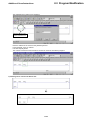
(3) Writing branch outputs
Here, the method of writing a branch output shown below is explained.
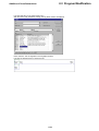
◊ Shift the cursor to the instruction description position (X0004 here) and press <Ctrl> + <↓> + <→> to draw a line.
◊ Left-click the [Common] or [Output] tab of the [Instruction group] tab on the ladder edit tool bar.
◊ Left-click the
[Output] button.
◊ Move the cursor to the position in which to describe an instruction and left-click that position.
The {Address Entry} dialog box is displayed.
Move the cursor to this
position and left-click it.
2-15
2-2 Programming
Writing contacts and outputs
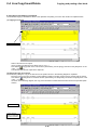
◊ Enter the address of the output in the [Address] text box.
In this example, <Y21> is entered.
◊ Left-click the [OK] button.
The branch output is connected as shown below.
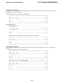
<Writing contact “X0008”>
◊ Left-click the [Common] or [Contact] tab of the [Instruction group] tab on the ladder edit tool bar.
[Examine On] button.
◊ Left-click the
◊ Move the cursor to the position in which to describe an instruction and left-click that position.
The {Address Entry} dialog box is displayed.
Move the cursor to this
position and left-click it.
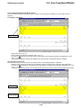
◊ Enter the address of the contact in the [Address] text box.
In this example, <X8> is entered.
◊ Left-click the [OK] button.
As shown below, the contact is connected to the left side of output “Y0021.”
2-16
2-2 Programming
Writing contacts and outputs
2-17
2-2 Programming
Writing a returning
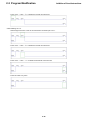
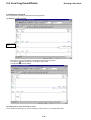
2-2-2 Writing a returning
The method of describing a “Returning” instruction is explained below.
(1) Writing returning (output)
First, the method of writing a returning (output) is explained.
◊ Shift the cursor to the right side of the instruction description position. Press <Ctrl> + <→> to draw a horizontal line
to the right bus.
Move the cursor to this
position and left-click it.
◊ The loop source is automatically written with a loop number.
Loop automatically
numbered
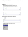
(2) Writing returning (input)
Next, the method of describing a returning (input) is explained.
1) Preparing line block starting point
◊ When the cursor is at the loop destination, insert a row by pressing <Ctrl> + <Ins>. The next loop start destination
point is inserted. The loop is automatically numbered by the loader.
Newly inserted loop
destination start point
2-18
2-2 Programming
Writing a returning
2) Creating a line at the loop destination
◊ Shift the cursor to the right of the arrow at the loop destination.
◊ Left-click the
[Examine On] button.
◊ Click the mouse left button to create a line.
Position the cursor here
and click the mouse left
button.
◊ Create a line as explained elsewhere.
See 2.2.1 for the
creation method.
Created loop
destination
instruction
2-19
2-2 Programming
Writing Inverse instruction
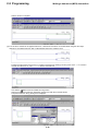
2-2-3 Writing Inverse instruction
The method of describing an “Invert” instruction is explained below.
◊ Left-click the [Contact] tab of the [Instruction group] tab on the ladder edit tool bar.
◊ Left-click the
[Invert] button.
◊ Move the cursor to the node in which to describe an instruction, and left-click that node.
An “Invert” instruction is described in the program window.
For the method of describing
a contact, refer to “2-2-1.”
“Inverse” instruction that
has been prepared
◊ Write in the output to complete the line.
For the method of describing
an output, refer to “2-2-1.”
2-20
2-2 Programming
Writing ON-delay timer
2-2-4 Writing ON-delay timer
The method of describing an “ON-delay timer” is explained below.
◊ Left-click the [Timer/Counter/Time Operation] tab of the [Instruction group] tab on the ladder edit tool bar.
◊ Left-click the
[ON-Delay Timer] button.
◊ Move the cursor to the node in which to describe an instruction, and left-click that node.
The {Address Entry} dialog box is displayed.
Enter a timer address.
Enter a timer setting time.
◊ Enter a timer address in the [Address 1] text box.
In this example, <T1> is entered.
◊ Enter a timer setting time in the [Address 2] text box.
In this example, <300> is entered (the timer starts three seconds later).
◊ Left-click the [OK] button.
An “ON-delay timer” is described in the program window.
2-21
2-2 Programming
Writing Up counter
◊ Write in a timer output contact and an output line to complete the line block.
For the method of describing
a contact and an output, refer
to 2-2-1.
Prepare a line separate from
the timer line, above.
2-2-5 Writing Up counter
The method of describing an “Up counter” is explained below.
◊
◊
◊
◊
Prepare a normally open contact (address: X0001) beforehand.
Left-click the [Timer/Counter/Time Operation] tab of the [Instruction group] tab on the ladder edit tool bar.
Left-click the
[Up Counter] button.
Move the cursor to the node in which to describe an instruction, and left-click that node.
The {Address Entry} dialog box is displayed.
Enter a counter address.
Enter a counter setting time.
◊ Enter a counter address in the [Address 1] text box.
In this example, <C1> is entered.
2-22
2-2 Programming
Writing contacts and outputs
◊ Enter a counter setting time in the [Address 2] text box.
In this example, <50> is entered.
◊ Left-click the [OK] button.
An “Up counter” is described in the program window.
Next, add a contact for
resetting the current value
of the counter.
◊ Left-click the [Common] or [Contact] tab of the [Instruction group] tab on the ladder edit tool bar.
◊ Left-click the
[Examine On] button.
◊ Move the cursor to the position in which to describe an instruction and left-click that position.
The {Address Entry} dialog box is displayed.
◊ Enter the address of the contact in the [Address] text box.
In this example, <X10> is entered.
◊ Left-click the [OK] button.
A contact is inserted as shown below.
2-23
2-2 Programming
Writing Up counter
◊ Write in a counter output contact and an output line to complete the line block.
2-24
2-2 Programming
Writing a data move (MOV) instruction
2-2-6 Writing Data Transfer (MOV) instruction
(1) The method of describing a “Data Transfer” (MOV) instruction is explained below.
◊ Left-click the [Transfer] tab of the [Instruction group] tab on the ladder edit tool bar.
◊ Left-click the
[Move] button.
◊ Move the cursor to the position in which to describe an instruction and left-click that position.
The {Address Entry} dialog box is displayed.
Enter the address from which to
transfer data.
Enter the address to which
data is to be transferred.
◊ Enter the address from which to transfer data in the [Address 1] text box.
In this example, <WX5> is entered.
◊ Enter the address to which data is to be transferred in the [Address 2] text box. In this example, <WM10> is
entered.
◊ Left-click the [OK] button.
A Data Transfer instruction (MOV) with a condition contact is described as shown in the following diagram.
2-25
2-2 Programming
Writing a data move (MOV) instruction
◊ Write a contact to complete.
(2) If an OR line is created for an applied instruction, a data move instruction can be described using the other input
method for an applied instruction that is called applied instruction guidance input.
◊ Position the right frame of the cursor to a vertical connection line drawing point and press <Ctrl> + <↓> to draw a
vertical connection line or <Ctrl> + <→> to draw a horizontal one.
◊ Left-click the
[Data Instruction Guidance Entry] button.
◊ Shift the cursor to the instruction description position and click the mouse left button.
The {Data Instruction Entry} dialog box is displayed.
2-26
2-2 Programming
Writing a data move (MOV) instruction
◊ Select [Category] from the {Data Instruction Entry} dialog.
◊ Select [MOV] from [Instruction List].
◊ Left-click the [OK] button.
The {Address Entry} dialog box is displayed for applied instruction MOV as follows:
◊ Enter a move-from address into the [Address 1] text box.
Enter <WX6> here.
◊ Enter a move-to address into the [Address 2] text box.
Enter <WM11> here.
◊ Left-click the [OK] button.
An OR line for an applied instruction created as follows:
About the Data Instruction Entry Guidance:
This guidance enables applied instruction input without switching the instruction group on the ladder edit tool bar.
2-27
2-2 Programming
Instruction input notes
2-2-7 Instruction input notes
(1) JUMP and JEND instructions
Enter a jump destination number with H (ex. H01). This number is accepted even P is added at input.
(2) Master Control Set (MC) and Master Control Reset (MCR) instructions
Enter a node number into the Address 1 textbox and a memory number into the Address 2 textbox. For Master Control
Reset, enter corresponding node numbers.
(3) Constant input
When entering a hexadecimal value, add H as an identifier. (ex. H0100). When entering a decimal value, do not attach any
identifier. (Do not enter “k” as an identifier necessary for the handheld loader.)
2-28
2-3 Program Modification
Changing instructions/addresses
Here, the method of modifying or changing a program that has been prepared is explained.
2-3-1 Changing instructions/addresses
The method of changing an instruction (symbol) and an address in the following program is explained below.
◊ Left-click the [Common] or [Contact] tab of the [Instruction group] tab on the ladder edit tool bar. (To change an
instruction too, previously select the new instruction button by left-clicking it.)
◊ Left-click the
[Examine Off] button.
◊ Move the cursor to the instruction (symbol) to be changed, and left-click the instruction.
The {Address Entry} dialog box is displayed.
◊ Change the address that is displayed in the [Address] text box (the address that has been entered).
In this example, <X10> is entered.
◊ Left-click the [OK] button.
The {Tag Edit} dialog box is displayed.
If the [Auto Documentation] check box is OFF at [Edit Options] in the environment setup, the {Tag Editor} dialog box
is not displayed.
2-29
2-3 Program Modification
Writing Inverse instruction
◊ Enter a tag name in the [Tag] text box.
In this example, <Motor Start> is entered.
◊ Enter an explanatory statement in the [Description] text box as required.
◊ Left-click the [OK] button.
The contact and tag name are changed.
Tag:
If once the tag name is defind (“X0000:Start Switch” in this sample), it is stored in a tag data base. For information
on changeing or deleting it.
refer to “2-5 tag Editor”.
2-30
2-3 Program Modification
Addition of lines/instructions
2-3-2 Addition of lines/instructions
Here, the method of adding a new line or instruction to an existing program is explained.
(1) Inserting a new line
The method of inserting a new line into a program is explained below.
Add this line.
◊ Shift the cursor to the line (instruction symbol) below the insertion position for a line block start point.
Left-click the line
at this position.
◊ Left-click the [Insert Line] button on the ladder edit tool bar.
The line block starting point is inserted.
The newly inserted line
block starting point
Position of [line insertion]
When the
[Insert Line] button on the ladder edit tool bar is clicked, a new line is inserted before the current
cursor line.
When the
[Insert Line Below Cursor] button on the ladder edit tool bar is clicked, a new line is inserted after the
current cursor line.
2-31
2-3 Program Modification
Addition of lines/instructions
◊ Write a contact and an output at the newly inserted “line block starting point” as shown in the following diagram.
(2) Inserting a new contact
The method of inserting a contact into a series line and the method of inserting a contact into a branch line are explained
below.
1) Inserting a contact into a series line
◊ Shift the cursor to the contact on the right side of the instruction insertion position.
Contact insertion position
◊
◊
◊
◊
Press <Ctrl> + <Ins> to reserve a space for writing a contact.
Left-click the [Common] or [Contact] tab of the [Instruction group] tab on the ladder edit tool bar.
Left-click the
[Examine On] button.
Move the cursor to the position in which to describe an instruction and left-click that position.
2-32
2-3 Program Modification
Addition of lines/instructions
The {Address Entry} dialog box is displayed.
Move the cursor to this
position and left-click it.
◊ Enter the address of the contact in the [Address] text box.
In this example, <X15> is entered.
◊ Left-click the [OK] button.
The contact is inserted in series between contacts as shown in the following diagram.
2) Inserting series contact into branch line
2-33
2-3 Program Modification
Addition of lines/instructions
◊ A contact is inserted on the left side of the cursor. Here, insert a contact between the bus and contact. Shift the
cursor to the contact on the right side of the instruction insertion position.
Press <Ctrl> + <Ins> to reserve a space.
◊ Left-click the Common tab or the Contact tab in the Instruction Group tabs on the ladder edit tool bar.
◊ Left-click the
[Examine On] button.
◊ Move the cursor to the position in which to describe an instruction and left-click that position.
The {Address Entry} dialog box is displayed.
Move the cursor to this
position and left-click it.
2-34
2-3 Program Modification
Addition of lines/instructions
◊ Enter the address of the contact in the [Address] text box.
In this example, <X16> is entered.
◊ Left-click the [OK] button.
As shown below, the contact is inserted and the “branch down” shifts to the right.
3) Inserting branch contact into branch line
2-35
2-3 Program Modification
Addition of lines/instructions
◊ A contact is inserted below the cursor. Shift the cursor above the instruction insertion position.
Press <Alt> + <Ins> to reserve a space.
Press <Ctrl> + <↓> or <Ctrl> + <←> to draw a connection line.
◊ Left-click the [Common] or [Contact] tab of the [Instruction group] tab on the ladder edit tool bar.
◊ Left-click the
[Examine On] button.
◊ Move the cursor to the position in which to describe an instruction and left-click that position.
2-36
2-3 Program Modification
Addition of lines/instructions
The {Address Entry} dialog box is displayed.
Position the cursor here and
click the mouse left button.
◊ Enter the address of the contact in the [Address] text box.
In this example, <X17> is entered.
◊ Left-click the [OK] button.
As shown below, the contact is inserted in parallel between the upper and lower contacts.
◊ Shift the cursor to the lower line for conversion.
2-37
2-3 Program Modification
Addition of lines/instructions
(3) Editing connecting lines
Here, the method of inserting or deleting connecting lines between instruction symbols (vertical and horizontal lines) is
explained.
1) Deleting vertical connecting line
◊ Shift the cursor to the upper left end of the vertical connection line to erase.
Press <Ctrl> + <Alt> + <↓> to erase one vertical connection line as the cursor moves.
2-38
2-3 Program Modification
Addition of lines/instructions
2) Writing a vertical connection line
◊ Shift the cursor to the upper left end of the vertical connection line to insert.
Press <Ctrl> + <↓> to draw a connection line downward from the right end of the selected instruction symbol.
3) Writing a horizontal connection line
◊ Shift the cursor to the left side of the space reserved for a path (horizontal connection line).
Press <Ctrl> + <→> to draw a horizontal connection line.
2-39
2-3 Program Modification
Addition of lines/instructions
(4) Compressing the program (removing blanks)
A line is compressed upward or to left if it permits vertical or horizontal compression by removing blanks left after program
creation.
The compression procedure is as follows:
◊ When the cursor is shifted to another line, this loader automatically converts and compresses the current program.
(5) Inserting a line (inserting a blank line)
This function is used to create a blank line in a line.
(This is different from line insertion.) When creating a parallel line, it is recommended to create a blank line in advance for
easy edit.
◊ Press <Alt> + <Ins> to create a blank line below the instruction line at the cursor position.
2-40
2-3 Program Modification
Addition of lines/instructions
(6) Deleting a contact or coil
A contact or coil can be deleted by shifting the cursor to its symbol and pressing the <DEL> key. However, a coil cannot
be deleted from the first line of a line.
Example: Delete a contact or coil from the following line.
• Deleting contact X1
◊ Shift the cursor to X1.
◊ Press the <DEL> key to shift the cursor from the current line to another.
• When deleting contact M0
The connection line remains even when the <DEL> key is pressed. Therefore, use the <Ctrl>, <Alt>, and arrow keys
instead.
◊ Shift the cursor to the position shown below.
◊ Press <Ctrl> + <Alt> + <←> to delete M0000.
2-41
2-3 Program Modification
Addition of lines/instructions
◊ Press <Ctrl> + <Alt> + <↑> to delete the vertical connection line.
• When deleting coil Y11
◊ Shift the right end of the cursor to the vertical line connection part of Y11.
◊ Press <Ctrl> + <Alt> + <↓> to delete the vertical connection line.
◊ Press <Ctrl> + <Alt> + <→> to delete the horizontal connection line.
◊ Press the <DEL> key twice.
2-42
2-3 Program Modification
Addition of lines/instructions
• When deleting coil Y10
Since a coil cannot be deleted directly from line 1, a coil should be deleted from line 2 and the address of the coil in line 2
is changed from Y10 to Y11.
◊ Delete Y11 by the procedure mentioned before.
◊ Double-click Y10 to change the address to Y11.
(7) Merging lines
Two independent lines can be merged into one. This is useful when connecting two independent lines vertically.
◊ Shift the cursor to a line to connect vertically.
◊ Select [Merge with Next Line] from the [Edit] menu. The line at the cursor position is merged with the one below.
◊ Align the right side of the cursor with the vertical line drawing position.
◊ Press <Ctrl> + <↓> to draw a vertical connection line.
2-43
2-3 Program Modification
Addition of lines/instructions
(8) Dividing a line
A line can be divided by erasing a vertical connection line.
◊ Align the right side of the cursor with the vertical connection line to erase.
◊ Press <Ctrl> + <Alt> + <↓> to erase the vertical connection line.
◊ When the cursor is shifted to another line, the current line is divide into two.
2-3-3 Changing a tag
This subsection explains how to change an input tag on a ladder window.
◊ Shift the cursor to X0000.
◊ Click the mouse right button to display the {Right Click} menu.
2-44
2-3 Program Modification
Addition of lines/instructions
◊ Left-click [Edit Tag] on the {Right Click} menu.
With the cursor at an address to change, the Tag Editor window is displayed.
◊ Enter “Switch 0” into the Tag field on the Tag Editor window.
◊ Left-click the [Close] button to change the tag.
2-45
2-4 Line Copy/Insert/Delete
Selecting a line block
Here, the method of copying or cutting one or more line blocks and pasting them to some other place and the method of
deleting unnecessary line blocks are explained.
2-4-1 Selecting a line block
In order to copy, cut, or delete a line, it is necessary first to select a or groups of line.
Refer to “(1)
Selecting a single
line block.”
Refer to “(2)
Selecting two or
more line blocks.”
(1) Selecting a single line block
◊ Move the cursor to the line to be selected.
◊ Left-click the mouse with the <Shift> key kept pressed.
The area of the selected line block is filled with a specified color. Specify a color in environment setup.
The selected area is
colored.
* Releasing select status:
To deselect a selected square area, press the <ESC> key or left-click.
2-46
2-4 Line Copy/Insert/Delete
Selecting a line block
(2) Selecting two or more line blocks
◊ Move the cursor to the first one of the line blocks to be selected and left-click it.
◊ Using the scroll bar, let the last one of the line blocks to be selected be displayed. Then, left-click that line block with
the <Shift> key kept pushed.
(When selecting a line outside the program window, press an [arrow] button while holding down the <Shift> key,
<Page Up>, or <Page Down> key at the current position on the first line block to display and select the last line
block.)
The selected line block is filled with a specified color.
The selected area is
colored.
* Releasing select status:
To deselect a selected square area, press the <ESC> key or left-click.
Select square area:
When selecting area, press an [allow] button while holding down <Shift> key and <Alt> key.
It is possible to copy and paste a selected square area to some other location.
To deselect a selected square area, press the <ESC> key or left-click.
2-47
2-4 Line Copy/Insert/Delete
Copying and pasting a line block
2-4-2 Copying and pasting a line block
The method of copying a selected line block to the clipboard and pasting it to some other location is explained below.
(1) Copying a line block
Copy this line block.
◊ Select a line block to be copied.
(For the method of selecting a line block, refer to “2-4-1.”)
◊ Left-click the
[Copy] button in the main window. (Alternatively, use the [Copy] command in the [Edit] menu or the
<Ctrl> + <C> keys.)
The selected line block is copied to the clipboard.
(2) Pasting the copy of line block
The method of pasting the copy of the line block to the position shown in the following diagram is explained.
◊ Move the cursor to the line containing contact address “X0005” (normally closed contact), and left-click the mouse.
[Paste] button in the main window. (Alternatively, use the [Paste] command in the [Edit] menu or the
◊ Left-click the
<Ctrl> + <V> keys.)
As shown in the following diagram, the copy of the line block is inserted before the line block at the specified paste
location.
Pasted line block
Specify this line
block to manipulate
the paste operation.
2-48
2-4 Line Copy/Insert/Delete
Selecting a line block
2-4-3 Cutting and pasting line block (move)
Here, the method of cutting a selected line block, copying it to the clipboard, and pasting it to some other location is
explained.
(1) Cutting a line block
Cut this line block.
◊ Select a line block to be cut.
(For the method of selecting a line block, refer to “2-4-1.”)
◊ Left-click the
[Cut] button in the main window. (Alternatively, use the [Cut] command in the [Edit] menu or the
<Ctrl> + <X> keys.)
The selected line block is copied to the clipboard, and the line block in the program window is deleted.
(2) Pasting the cut line block
The method of pasting the cut line block to the location shown in the following diagram is explained.
◊ Move the cursor to the line containing contact address “X0005” (normally closed contact) and left-click the line.
[Paste] button in the main window. (Alternatively, use the [Paste] command in the [Edit] menu or the
◊ Left-click the
<Ctrl> + <V> keys.)
As shown in the following diagram, the cut line block is inserted before the line block at the specified paste location.
Pasted line block
Specify this line
block to manipulate
the paste operation.
2-49
2-4 Line Copy/Insert/Delete
Deleting a line block
2-4-4 Deleting a line block
Here, the method of deleting a selected line block is explained.
(1) Deleting a single line block
Delete this line
block
◊ Move the cursor to the line block to be deleted and left-click the line block.
◊ Left-click the
[Delete Line] button on the [Edit Line] tool bar.
The selected line block is deleted.
(2) Deleting two or more line blocks at a time
For the method of deleting two or more line blocks at a time, refer to “2-4-3 Cutting line blocks.”
2-50
2-5 Tag Editor
Outline of Tag Window
There are two methods for preparing tags. One is using the {Tag Editor} dialog box that is displayed after the entry of an
instruction address during program editing. The other is using the {Tag Editor} window explained below.
2-5-1 Outline of Tag Window
The {Tag Editor} window consists of a search section for search and replacement, a filter to limit the objects of display and
edit, and a tag editor.
The {Tag Editor} is capable of directly editing address/tag data bases. This editor can be used only when the program
window is in the Edit mode.
<Getting the Tag Editor to be displayed>
◊ Left-click the
[Tag Editor] button or select the [Tag Editor] command from the [Auxiliary Functions] menu in the
main window.
The {Tag Editor} window is displayed.
Search section
Filter section
Tag editor
{Tag Editor} window in initial state
2-51
2-5 Tag Editor
Operation with Tag Editor
2-5-2 Operation with Tag Editor
Here, the controls and fields on the tag Editor and the method of editing records (contents of records) are explained.
(1) Configuration of Tag Editor
1) Address field
2) Tag field
5) Field name/operation bar
4) Tag edit tool bar
3) Description field
1) Address field
“Addresses” of the PC memory are described in this field. Describe “addresses” within the PC memory capacity.
2) Tag field
“Tags” are described in this field. Each tag must be within 16 characters in length. For a tag, do not use a comma (,),
quotation marks (“ and ”), period (.), half-size numerals only, or address itself.
If <Permit identical tag> is enabled in environment setup, the same tag can be set with a different address.
3) Description field
“Descriptions” are described in this field. Each description must be within 50 characters in length. The comma (,) cannot be
used in descriptions. Any commas in a description are automatically deleted when the description is added to the data
base.
4) Tag edit tool bar
[First record]
Moves the cursor to the first record in the data base.
[Prior record]
Moves the cursor to the prior record in the data base.
[Next record]
Moves the cursor to the next record in the data base.
[Last record]
Moves the cursor to the last record in the data base.
[Insert record] Inserts a blank record right in front of the record at which the cursor is positioned.
[Delete record] Deletes the record at which the cursor is positioned. Before the record is deleted, the {Confirm}
dialog box is displayed.
[Edit record]
Sets the record at which the cursor is positioned in the Edit mode to enable the record to be edited.
[Post edit]
[Cancel edit]
Registers the record that is being edited. The record is registered after it is confirmed that the record
contains both an address and a tag, that the address format is valid, and that there is no tag
duplication.
Cancels the Edit mode and resets the record in the pre-edit state.
[Refresh data] Refreshes the record displayed from the data base.
2-52
2-5 Tag Editor
Operation with Tag Editor
5) Field name/operating bar
Displays field names. It also has the following functions.
<Changing field width>
To change the field width, move the cursor to any of the boundary lines between Address, Tag, and
Description, and shift it right or left with the left button of the mouse kept pushed.
<Changing order of display of fields>
Move the cursor into any of the frames of Address, Tag, and Description, and shift the frame right or left with the left
button of the mouse kept pushed.
While holding down the
mouse left button, shift
the cursor.
(2) Inserting a new tag
◊ Left-click the
[Insert record] button on the tag editor tool bar or push the <Insert> key. A blank record is inserted.
Newly inserted
record
◊ Enter addresses, tags, and descriptions.
The <Tab> key can be used to shift from the address to the tag to the description. The entry of a description may be
omitted. However, be sure to enter an address and a tag before the record is registered in the data base. Each time
a new record is registered, the records in the data base are automatically sorted (rearranged) in order of address.
2-53
2-5 Tag Editor
Tag Editor
2-5-3 Find and replacement using the tag editor
(1) Find section
Find text box
Replace text box
Enter an address or tag into the [Find] text box for search.
The address or tag entered into the [Find] text box is searched.
The address or tag entered into the [Replace with] text box is replaced.
When the [Ignore Case] check box is set to ON, an address or tag is searched by ignoring uppercase and
lowercase.
When the [Whole words only] check box is set to ON, a text is extracted with a half-size space or comma or ASCII
code other than A-Z (a-z) as a delimiter code address and searched as a word.
2-5-4 Tag editor filter
(1) Configuration of the filter section
Address text box
Tag text box
Description text box
Depending on the input contents of each text box, the tag editor displays only specified objects for edit.
2-5-5 Reading a tag text file
A text file (file extension: *.txt or *.csv) prepared by a word processor, data base application program, etc. can be imported
as tag data.
* CSV-format data
CSV (Comma Separated Value) refers to text data, each data item of which is separated by a comma (,).
(1) Text file format
For a text file to be input as tag data, it is necessary to describe each of its lines in the following format.
1) Text format
[Address],[Tag],[Description],[CR/LF]
• For [Address], describe a valid PC address (e.g., X0, Y0010, M20, C15, etc.).
• For [Tag], describe a tag which does not exceed 24 characters in length.
If it exceeds 16 characters in length, only 16 characters are input from the first character. A duplicate tag name is
ignored.
• For [Description], the entry of a description may be omitted. When entered, the description must not exceed 50
characters in length.
• [CR/LF] refers to carriage return. Be sure to put a [CR/LF] at the end of each line.
A tag cannot be read on an address to which a tag has already been assigned.
Before loading a tag, delete the existing tag using a tag editor.
2-54
2-5 Tag Editor
Tag Editor
2) Example of description of text data
An example of display on the program when the above text data is input as tag data is given later in “(3) Display of tag
after input to file.”
(2) Importing text file
◊ Open the program (file) to which the text data is to be input.
◊ Select the [Import Tag File...] command of the [Documentation] from the [Auxiliary] menu.
The {Import Tags from text Files} dialog box is displayed.
◊ Select a drive and a folder to which the file is to be saved from the [Look in] list box.
◊ Select from or enter in the [File name] list box a text filename to be input.
◊ Left-click the [Open] button.
The text file (data) is input to the specified tag file.
2-55
2-5 Tag Editor
Tag Editor
(3) Display of tag after inporting text file
Tag imported from text file are immediately displayed in ladder display. (provided that “tag display” in editor setting in the
environment setting session is valid).
An example of display is given below.
2-56
2-6 Line Comment Edit
Line Comment
A line comment can be used as an explanation of each line in a ladder program.
A line comment can be edited only when the program window is in Edit mode.
◊ In Edit mode, shift the cursor to a line to edit its comment.
◊ Select the [Insert/Modify Line Comment] command from the [Edit] menu.
If the line has no comment, the {Line Comment Number} dialog is displayed. The Comment No. text box displays
an unused line comment number in default. An arbitrary number may be entered.
◊ If the line has a comment, left-clicking the [OK] button on the Line Comment No. dialog displays the Edit Line
Comment dialog.
◊ Enter a line comment into the text box and left-click the [OK] button.
The display returns to the ladder window and the line comment is displayed.
If the cursor is at the current or next comment line, the line comment can be modified.
Execute the [Insert/Modify Line Comment] command to display the {Line Comment Editor} dialog for modifying a
line comment.
A line comment is saved at a selected place in the ladder program as a line comment instruction containing a line
comment number. Since a line comment is regarded as an instruction, a step is used and a line number is counted.
The line comment number is displayed and used to refewr to a text in the comment file.
2-57
2-6 Line Comment Edit
Line Comment
Irrespective of the locations, unused line comment numbers are automatically assigned in ascending order. If a
used number is entered, the text of the same number is displayed.
<Using the same line comment number>
◊ Create a line comment for 1) at “Line comment No. 002.”
◊ When the “Line Comment No.” dialog is displayed at 2), enter “0002” into the Comment No. text box.
◊ The same text as the line comment at 1) is displayed.
Since the line comments of 1) and 2) share the same line comment number, the alteration of either contents also
changes to the other.
When the [OK] button on the {Line Comment Editor} dialog is clicked, the line comment is saved into the comment
file.
2-58
2-7 Find/Replace Functions
Find function
2-7-1 [Address/Tag] Find function
The method of retrieving an instruction address and a tag in the program being displayed in the program window is
explained below.
(1) First retrieval
◊ Get the appropriate program to be displayed in the program window.
◊ Left-click the [Find] button or select the [Find] command from the [Search] menu.
The {Search} dialog box is displayed.
◊ Enter an address or a tag name in the [Address/Tag] text box and left-click the [Find] button to start the search
operation.
When the address (or tag name) is found, the associated line is displayed at the top of the screen. Since the dialog
box remains the same, press the [Find] button for the next search. If it is not found, the message “Search item not
found” is displayed in the message box.
This find function searches for only a character string which completely coincides with the input character string.
<Explanation of the {Search} dialog box>
Direction:
Either “Forward” (search from the beginning of the scope of search toward the end) or “Backward” (search from the
end of the scope of search toward the beginning) can be selected.
Origin:
This option specifies the starting point of search. As the starting point, either “From Cursor” or “Entire Scope” can
be specified.
Scope:
This option specifies the scope of search.
• Whole Program:
This is the default, searching the entire program.
• Selected Lines:
Only a previously selected line block is searched. For the method of selecting a particular
line block, refer to “2-4-1 Selecting a line block.”
Range:
This option specifies an instruction to be searched for.
• All Elements:
All instructions are searched for.
• Contact Instructions: Only contact instructions are searched for (normally open contact and normally closed
contact).
• Output Instructions: Only output instructions are searched for (normal Output/Set/Reset/Rising Differentiation
Output/Falling Differentiation Output).
• Data instructions:
Searches all instructions not contained in the above contact and output instructions.
2-59
2-7 Find/Replace Functions
Replace function
(2) Succeeding search
This item is used, after searching for an address or a tag name using the [Search] command explained in {(1) First
search}, to search for the same address or tag name.The search options that have been selected in the [Search]
command remain valid. The search operation is started from the last address or tag name that has been found.
◊ By selecting the [Search Next] command from the [Search] menu, it is possible to continue the search operation.
2-6-2 [Address/Tag] Replace function
The method of searching for an instruction address and a tag name in the program being displayed in the program window
and replacing them with any specified character strings is explained below.
The Replace function can be used only when the program window is in the Edit mode.
◊ Get the appropriate program to be displayed in the program window.
◊ Left-click the
[Edit] button or select the [Edit Mode] command from the [Edit] menu. The program window enters
the Edit mode.
◊ Select the [Replace] command from the [Search] menu.
The {Replace} dialog box is displayed.
◊ Enter the address or tag to be replaced in the [Address/Tag] text box.
◊ Enter the new replacement address or tag in the [Replace with] text box.
◊ Left-click the [OK] button to start the replace operation.
When the replace operation is completed, the {Information} dialog box is displayed and the number of replaced
addresses or tags is displayed.
<Explanation of the {Replace} dialog box>
Items related to search:
For the explanation of the search options (direction, scope, origin, target), refer to “2-6-1 [Address/Tag] Search
function.”
Several addresses can be replaced simultaneously if a range of old addresses is specified using a hyphen (ex.
X10-X2F).
2-60
2-7 Find/Replace Functions
Replace function
Replace option :
This item is effective only when the entire program is to be searched for.
When [With Tag/Description] is selected, the tag is changed at the same time as the address. The tag name of the
address before replacement remains the same.
When [Delete Original] is selected, the tag name of the address before replacement is deleted.
<Example of simultaneous tag change>
When replacing address WB0 with WB50, processing is performed as follows:
(Before replacement)
(After replacement)
Address
Tag
Analog 0CH
WX6
Analog 0CH
Reserved
WX50
Analog 0CH
Address
Tag
Address
Tag
WX0
WX50
Delete Original not selected
This tag is changed
Delete Original selected
Deleted
WX0
WX50
Analog 0CH
When [Bit Device in Word Device] is selected, the bit addresses corresponding to the changed word address are
changed simultaneously.
Replace All A/B-Contacts:
This option replaces all NO and NC contacts of specific addresses in the specified scope. When this option box is
checked, the [Replace] text box is hidden. Here, enter the address in the [Address/Tag] text box. All instructions of
NO and NC contacts are replaced.
Key-point
Address replacement
All specific addresses in a specified scope are replaced with different addresses. Enter the address
to be replaced in the [Address/Tag] text box, and enter the replacement address in the [Replace with] text
box. A bit address can be only replaced with another bit address, and a word address can be only
replaced with another word address. As the bit address/word address to be replaced, either an address
or a tag may be entered. During the replace operation, the system checks whether or not the replacement
address can be used for the instruction to be executed. If the replacement address cannot be used,
the replace operation is not performed.
¥ Bit address
¥ Word address
¥ Tag
¥ Address
(bit/word)
¥ Bit address
¥ Word address
Bit address
Word address
Address
(bit/word)
Tag
2-61
X
X
Word address
Bit address
2-7 Find/Replace Functions
Search function
2-7-3 Line Search function
This function searches for the program of any specified line number and displays it at the top of the screen.
◊ Select the [Go to Line Number...] command from the [Search] menu.
The {Go to Line Number} dialog box is displayed.
◊ Enter the line number to be searched for in the [Line Number] text box.
◊ Left-click the [OK] button.
The specified line is displayed at the top of the screen.
Specified line number
2-62
Library registration function
2-8 Library Registration and Read
Specified lines can be fetched and registered as a library for use when necessary.
2-8-1 Library registration function
This subsection explains how to register specified lines in a library.
The library registration function can be used only when the [Edit Mode] button is ON and a ladder program is selected.
This function is executed on lines (single or multiple lines, excluding some lines). When registering lines in a library, a line
block should be selected first.
See 2-4-1 for selecting a line block.
◊ When an object line block is selected, select the [Copy to Library] command from the [Edit] menu. The {Copy to
Library} dialog box is displayed.
◊ Select a save-to drive or folder or create a new folder in the [Save in] list box.
◊ Select or enter a save-to library file name in the [File name] text box.
◊ Left-click the [Save] button.
The selected line block is saved in the file. The file extension is ‘LLB’ .
2-8-2 Library read function
This subsection explains how to paste a registered line from a library to a ladder program.
The library read function can be used only when the program window is in Edit mode.
◊ Display an object program on the window to paste lines from the library.
◊ Left-click the
[Edit] button or select the [Edit Mode] command from the [Edit] menu.
The program window changes to Edit mode.
◊ Shift the cursor to the line below the line paste position.
◊ Select the [Paste from Library] command from the [Edit] menu.
The {Paste from Library} dialog box is displayed.
2-63
2-8 Library Registration and Read
Library registration function
◊ Select a save-to drive or folder or create a new folder in the [Look in] list box.
◊ Select or enter a save-to library file name in the [File name] text box.
◊ Left-click the [Open] button.
The selected line is pasted from the library.
Line read from the
library
Specify this line
program to read
from the library
A line just pasted is in the selected status.
2-64
2-9 Function block
Outline of function block
A function block (User Macrocommand) makes a user-created program available as a subroutine. A created function block
can be saved in a function block library or called for user by another program. For using function block instructions, refer
to “ User Macrocommand Manual LEH943.”
2-9-1 Outline of function block (User Macrocommand)
(1) Describing a function block and displaying function block information
A function block is described in a program as a function block call section and function block execution sections.
1) Edit window
Function block call
section
Main program
Function block
execution section
Function block
execution section
2) Function block information display
◊ Set the program window to Edit mode.
◊ Select the [Function Block...] command from the [PC Functions] menu.
The {Display Function Block Information} dialog box is displayed.
2-65
2-9 Function block
Function block library
The [Call Function Block] command lists all function blocks called by the CALL instruction in a ladder program. These are
displayed in their order in the program. This list also displays the function block number called by the CALL instruction, the
line number where the CALL instruction is written, and whether the function block is loaded in the user program (Yes/No).
If a CALL instruction is issued to a function program not loaded, an error occurs and the PC does not start up.
Enter a function block number with H (ex. UM H0100).
The [Execute Function Block] command lists all function blocks loaded in the program with the numbers of steps used for
them.
2-9-2 Function block (User Macrocommand) library
(1) Saving into the function block library (the function block execution section → the function block library)
◊ Select a function block to save at [Execute Function Block].
◊ Left-click the Save button.
◊ The Save Function Block window is displayed.
◊ Select a location and left-click the [OK] button to save the function block.
(2) Adding or deleting a function block
1) Adding a function block from a function block library (the function block library → the function block execution
section)
◊ Left-click the Add button.
◊ The Select Function Block Library window is displayed.
2-66
2-9 Function block
Function block library
◊ Select a necessary function block and left-click the [OK] button to import the block from the function block library
into the function block execution section.
To set the default directory for a function block library, select [Options] - [Environment Options].
If a function block available for the current model is not found in the function block library, the Add button does not
become valid.
(3) Collating with the function block library (the function block library ↔ the function block execution section)
A function block at [Execute Function Block] is collated with one selected from the function block library.
◊ Select one of the function blocks at [Execute Function Block].
◊ Left-click the [Collate] button to display the {Verify Function Block with Library} dialog box.
◊ Select a function block to collate, then left-click the [OK] button to start collation. Match or mismatch is displayed.
2-67
2-9 Function block
Function block library
(4) Deletion from the function block execution section
◊ Select a function block to delete at [Execute Function Block], then left-click the [Delete] button.
(5) Deletion from the function block library
◊ Left-click the [Library FB Delete] button to display the Delete Function Block window listing function blocks that can
be deleted.
◊ Select a function block to delete, and left-click the [Delete] button.
2-68
2-10 Parameter Setting
Displaying parameter setting dialog box
This manual explains how to display and operate parameter setting dialog box.
For the details of parameter settings, refer to User’s Manual (Instructions)
2-10-1 Displaying parameter setting dialog box
This subsection explains how to display parameter setting dialog box.
Parameter settings are registered in the same file as the program. Therefore, open the parameter setting program (file)
first.
◊ Open the program (file).
◊ Select the [System Parameters...] command from the [PC Functions] menu.
2-69
2-10 Parameter Setting
Operating parameter setting dialog box
2-10-2 Operating parameter setting dialog box
The parameter setting dialogs can roughly be classified into six. This subsection explains a display example of each
dialog box.
(1) Processor operation definition dialog box
This dialog is used to define the module operations (I/O status and other) in the entire PC system, processor, and
processor-mounted base board.
<SPB dialog box>
<NB/NJ/NS dialog box>
<NB0 dialog box>
2-70
2-10 Parameter Setting
Operating parameter setting dialog box
(2) Area setting dialog box
This dialog is used to set the file register capacity and latch (hold) areas.
(3) Input filter setting dialog box
This dialog is used to set the input filter values.
<NB/SPB dialog box>
<NS/NJ dialog box>
2-71
2-10 Parameter Setting
Operating parameter setting dialog box
(4) High-speed counter setting dialog box
This dialog box is used to define the built-in high-speed counters.
<NB dialog box>
<SPB dialog box>
(5) I/O configuration setting dialog box
This dialog box is used to set the I/O configuration of the NS/NJ Series.
2-72
2-10 Parameter Setting
Operating parameter setting dialog box
(6) Other function setting dialog box
<SBP general-purpose communication interface setting dialog box>
This dialog box is used to set the loader interface, general-purpose communication adapter, and easy CPU link
adapter.
<CPU RS-232C port setting dialog box for NS/NJH Series>
This dialog box is used to set the operations of the RS-232C port with the CPU.
<Option setting dialog box for NS/NJH Series>
This dialog box is used to fix the occupied address of the option module at 0 and to set the first address of an
extension unit.
2-73
2-10 Parameter Setting
Operating parameter setting dialog box
<Extended parameter setting dialog for NB Series>
This dialog box is used to enable or disable the interrupt input or pulse input filter.
When this dialog box is checked, the filter becomes valid and operates according to the input filter setup.
2-74
Saving a program
2-11 Program Saving and Opening
This section explains how to save the current program and to open an existing program.
2-11-1 Saving a program
This section explains how to save the current program (contents of the program window now displayed).
(1) Saving a program into a file
◊ Select the [File] menu.
The following commands are displayed:
Save in a program file.
If this command is executed again
after a file once saved is modified,
the program contents are saved on
the original file.
Save as a new program file.
The program contents can be saved
as a separate file by specifying a
drive name, folder name, and file
name.
◊ Select the [Save As...] command.
The {Save As} dialog box is displayed.
One of the following file types can be selected:
• Ladder file (*.Fxl):
File of the Windows V2.0 format
• Old ladder file (*.Lad):
File of the Windows V1.0 format
• DOS Loader file (*.Pma): File of the MS-DOS Loader format
◊ Select a save-to drive or folder or create a new folder in the [Save in] list box.
◊ Select or enter a save-to file name in the [File Name] text box.
◊ Left-click the [Save] button.
The program contents are saved as a new file.
2-75
2-11 Program Saving and Opening
Saving a program
(2) File contents when a program is saved
If a program is saved in a file, the following contents are also saved:
• Saving in the ladder file (.Fxl) format
<*.FXL file>
• PC model information
• Parameter
• Program
<*.FXP file > (Can be specified for loader version V2.1.1.0 or later.)
• Parameter
<*.TAG file>
• Address tag and explanation
<*.CMT file>
• Line comment (Text only. An instruction indicating the line comment display position is saved in the *.FXL file.)
<*.DTA file>
• Data register contents
• Saving in the old ladder file (*.LAD) format of the Windows version (V1.
<*.LAD file>
• Ladder program
• SFC program
• PC function information
• Parameter
• File register contents
<*.TAG file>
• Address tag and explanation
<*.DTA file>
• Data register contents
• Saving in the DOS Loader file format
<*.PMA file>
• Program
<*.PRM file>
• PC model information
• Parameter
<*.CTD file>
• Comment file
<*.AMD file>
• Data register contents
Note: Each of the PC model information and program cannot be stored alone.
2-76
)
Saving a program
2-11 Program Saving and Opening
2-11-2 Opening a program
This subsection explains how to open a program file already saved.
◊ Select the [File] menu.
The following commands are displayed:
◊ Select the [Open] command.
The [Open Ladder File] dialog box is displayed.
◊ Select a save-to drive or folder or create a new folder in the [Look in] list box.
◊ Select or enter a save-to file name in the [File Name] text box.
◊ Left-click the [Open] button.
The window displays the program.
2-77
2-12 Import/Export
Import
2-12-1 Import
(Loading the parameter, data, and tag files by specifying them separately)
This function loads the contents of the parameter, data, and tag stored in the program currently loaded. When you load a
new parameter or tag and then execute the [Save] command, the {Save As} dialog box is displayed allowing you to store it
under a new file name.
◊ Select the [File] menu.
The following command menu is displayed.
◊ Select the [Import...] command.
The {Import} dialog box is displayed.
◊ Left-click the [Browse...] button to display a dialog box. Select the drive and holder in which the file to be imported is
stored.
◊ Select the file to be imported and then click the [>] button to move it to “Import files”.
To delete the file, click the [<] button or use the Delete key.
If you move a file with the same type (parameter, data, and tag) as the one in “Import file”, the existing file is
removed from “Import file”.
◊ Left-click the [OK] button to load the contents of the file.
2-78
2-12 Import/Export
Export
2-12-2 Export
(Saving the parameter, data, and tag files by specifying them separately)
This function saves the contents of the parameter, data, and tag stored in the program file currently loaded under a
specified file name.
◊ Select the [File] menu.
The following command menu is displayed.
◊ Select the [Export...] command.
The {Export} dialog box is displayed.
◊ Specify the parameter, data, and tag to be saved separately.
Specify the drive, file name, and file type of the target file.
Using the [Browse...] button for each parameter, data register, and tag, select the target drive and holder and
specify the target file name.
◊ When the file name of a [tag] is specified by ***.CTD, specification of the range of a tag is possible.
◊ Left-click the [OK] button to save the specified parameter, data, and tag.
2-79
2-12 Import/Export
• The extensions of files which can be imported and exported are shown below.
Files for Windows loader
• Parameter file (*.FXP)
• Tag file (*.TAG)
• Data file (*.DTA)
Files for DOS loader
• Parameter file (*.PRM)
• Tag file (*.CTD)
(Comment file)
• Data file (*.ADM)
Note: The parameter file (*.FXP) cannot be opened with loader versions earlier than V2.1.1.0.
• The relation between the program file and parameter file is shown below.
[Save]
Program file
*.FXL
[Export]
Parameter file
*.FXP
Parameter file
*.FXP
The parameter file (*.FXP) is a file storing the parameters extracted from the program file.
Only the program cannot be extracted.
2-80
2-12 Import/Export
Property
2-12-3 Property
This function displays the name of the file currently loaded as a program file. If the program file is imported separately, the
file name is displayed for each file. The target location and file name are displayed.
This information displays the name of the file imported for the currently loaded program file. If you close the
program file and then open it again, the name of the imported file is not displayed. If you want to leave this
information, use the [Save] button.
◊ Select the [File] menu.
The following command menu is displayed.
◊ Select the [Property] command.
The {Property} dialog box is displayed.
◊ To save this information, press the [Save] button.
The data is saved in the text (CSV) format.
2-81
2-13 Mnemonic Instructions
Outline of mnemonic edit windows
This section explains how to edit a program by mnemonic instructions.
2-13-1 Outline of mnemonic edit windows
The mnemonic edit windows can be classified into two types. [Display Edit Line Instruction] displays the line at the cursor
position and [Display Line as Instruction List] displays all lines of a ladder program. These windows displays lines as
mnemonic codes. Instructions can be edited in Edit mode only.
A mnemonic code is displayed in the following format:
Instruction code
’ Tag ’ ( Address )
Operand
If no tag is entered or only address display is set at [Environment Setup] - [Display Address/Tag].
Instruction code
Address
Operand
If only tag display is set at [Environment Setup] - [Display Address/Tag].
Instruction code
’ Tag ’
Operand
(1) Displaying edit line instructions
◊ Shift the cursor to the object line.
◊ Left-click the [Display Line Instruction] on the Edit Line toolbar or select the [Display Line Instruction] command
from the [Edit] menu.
A cursor-specified line is displayed in the mnemonic code format.
One line can be edited in Edit mode.
2-82
2-13 Mnemonic Instructions
Editing a mnemonic instruction
(2) Displaying an instruction list
◊ Select the {Display All as Instruction List} command from the [Edit] menu.
The lines of a ladder program are displayed as mnemonic codes.
2-13-2 Editing a mnemonic instruction
◊ Left-click the [Edit] Mode button or select the [Edit Mode] command from the [Edit] menu on the main window.
The display changes to the ladder program edit window.
◊ Select the [Display Line as Instruction List] command from the [Edit] menu on the main window.
The display changes to the mnemonic code edit window.
◊ Left-click the [Insert Line] button on the ladder edit toolbar or press <Alt> + <Ins>.
One line is inserted before the cursor with an NOP instruction.
If an instruction list is displayed by the New command, a NULL code is displayed.
This is a special instruction inserted when a line is not complete or in the middle of line edit. The user need not
mind this instruction because the instruction is automatically deleted if the line becomes correct.
◊ Shift the cursor to NOP where to write an instruction. Create a program by rewriting the NOP.
The input methods are as follows:
(1) Direct input from the keyboard
(2) Input by [Instruction group] tab functions on the ladder edit tool bar
2-83
2-13 Mnemonic Instructions
Outline of mnemonic edit windows
◊ Like a ladder program, an instruction is converted when the cursor is shifted from the position after instruction
operands are entered.
By the <TAB> key, shift the cursor to the [Instruction group] tab on the ladder edit tool bar. Then the tab can be
switched using the <←> or <→> key.
A program is saved not only by instruction list display but also by ladder line display.
2-84
Section 3 Online Operations
Page
3-1 Preparation for Online Connection and Outline of Online Operations .................. 3-1
3-1-1 Hardware system configuration ............................................................................................. 3-1
3-1-2 Setting communication parameters for the loader ................................................................ 3-2
3-1-3 Outline of online operations .................................................................................................. 3-3
3-2 Online Connection ...................................................................................................... 3-4
3-3 Save PC Content to File ............................................................................................. 3-6
3-3-1 Save PC program .................................................................................................................. 3-6
3-3-2 Saving PC data ..................................................................................................................... 3-7
3-4 Transfer ()Verify Contents of File to the PC .............................................................. 3-8
3-4-1 Transfer contents of program file to the PC ........................................................................... 3-8
3-4-2 Transfer contents of data file to the PC ............................................................................... 3-12
3-4-3 Transfer contents of parameter file to the PC ...................................................................... 3-13
3-4-4 Comparing file contents with PC contents .......................................................................... 3-14
3-5 Start/Stop the PC ...................................................................................................... 3-15
3-6 Change Online Program ........................................................................................... 3-16
3-7 PC Memory Clear ...................................................................................................... 3-18
3-7-1 Clearing PC memory with online window kept open ........................................................... 3-18
3-7-2 Clearing PC memory without opening online window ......................................................... 3-19
3-8 Displaying and Setting Data .................................................................................... 3-20
3-8-1 Displaying data .................................................................................................................... 3-20
3-8-2 Setting data ......................................................................................................................... 3-23
3-9 PC Diagnosis ............................................................................................................. 3-24
3-10 Loader Network (1:n Communication) .................................................................. 3-25
3-10-1 Network Connect .............................................................................................................. 3-26
(1) Online connection ................................................................................................................................. 3-26
3-10-2 Changing or releasing the destination of network connection .......................................... 3-27
3-11 Sampling Trace (Recording of Data History) ........................................................ 3-28
(1) Trigger specification by program instruction .......................................................................................... 3-29
(2) Trigger specification by device start and end ........................................................................................ 3-30
3-11-1 Setting sampling trace ...................................................................................................... 3-32
3-11-2 Sampling trace execution .................................................................................................. 3-32
(1) Methods of execution by the program loader ........................................................................................ 3-32
(2) Method of execution by a program ........................................................................................................ 3-32
3-11-3 Display of sampling trace .................................................................................................. 3-34
3-11-4 Saving sampling trace data ............................................................................................... 3-35
3-11-5 Sampling trace cancel all .................................................................................................. 3-36
3-12 Status Latch (Recording Data at a Point of Time) ............................................... 3-37
3-12-1 Outline of function ............................................................................................................. 3-37
3-12-2 Creating a program ........................................................................................................... 3-37
(1) Example of the program to execute status latch by key operation on the program loader ................... 3-37
(2) Sample program using the SLT instruction ........................................................................................... 3-38
(3) Example of the program to execute status latch by operating external input switch B1O ..................... 3-38
3-12-3 Status latch registration .................................................................................................... 3-39
3-12-4 Status latch execution ....................................................................................................... 3-40
(1) Method to operate keys of the program loader ..................................................................................... 3-40
(2) Using a program ................................................................................................................................... 3-40
(3) The method to operate external input switch for execution ................................................................... 3-41
3-12-5 Status latch result display ................................................................................................. 3-41
3-12-6 Saving status latch data .................................................................................................... 3-42
3-12-7 Status latch cancel all ....................................................................................................... 3-42
Hardware system configuration
Section 3 Online Operations
3-1 Preparation for Online Connection and
Outline of Online Operations
3-1-1 Hardware system configuration
Connect a personal computer using the PC loader cable for FLEX-PC/N.
NJ
0
1
2
8
9
A
3
B
4
C
5
D
6
E
7
F
RS-232C
• Applicable personal computer
• Connection cable
¥ PC/AT-compatible machine
¥ NN-CNV3 (9-pin D-subconnector)
3-1
0
8
1
9
2
A
3
4
B
C
5
D
6
E
7
F
0
8
1
9
2
3
A
B
4
C
5
D
6
E
7
F
0
1
2
8
9
A
3
B
4
C
5
D
6
E
7
F
0
1
8
9
2
A
3
B
4
5
C
D
6
E
7
F
0
8
1
9
0
8
2
A
1
9
3
4
B
C
2
3
A
B
0
1
2
8
9
A
5
D
4
C
6
3
E
5
B
D
7
4
F
C
6
E
7
F
5
D
6
E
7
F
3-1 Preparation for Online Connection and
Outline of Online Operations
Setting communication
parameters for the loader
3-1-2 Setting communication parameters for the loader
Here, the procedure for adjusting communication parameters of the personal computer loader to those of the loader
adapter (or general-purpose interface capsule) is explained.
◊ Select [Options] - [Communications...] from the menu bar.
◊ The {Communication Parameters} dialog box is displayed.
Select a personal computer RS-232C port number (Com 1 to Com 9) from the [Communications] list.
Then, left-click the [Comm Port Properties] button.
◊ Check that the port is set as shown below. If incorrect, correct as follows. Then, left-click the [OK] button.
[Bits per second] in the dialog box is the same in meaning as “baud rate.”
Normally, select [1] for [Stop bit].
◊ The dialog box returns to the former one. Left-click the [OK] button. This is all for the setting of parameters.
3-2
Outline of online operations
3-1 Preparation for Online Connection and
Outline of Online Operations
3-1-3 Outline of online operations
The flowchart below shows an outline of online operations.
Start
Connect the PC to the personal computer.
Online
Monitor programs and data.
Monitor
Edit a program or data on the edit screen.
Edit
NO
Online write
YES
Load edited line data into
PC
Save in file
Stop PC
Loading
work
Load
Start PC
NO
Store program contents onto the
disk by specifying a file name.
Stop the PC.
Load file contents into the PC by
specifying a file name.
Restart the PC.
End of work
YES
Save in file
End
When loading a program into the PC, specify a file name. If the program has not been saved immediately after
monitoring or during edit, save the program once before loading.
3-3
3-2 Online Connection
Online Connection
Here, the method of connecting the personal computer online to the PC is explained.
This online connection is necessary when monitoring/editing PC programs, saving PC programs to the personal computer,
transferring personal computer programs to the PC, and so on.
After finishing “3-1 Preparations for online connection,” use the following procedure for online connection.
◊ Select [File] - [Online] from the menu bar.
(Alternatively, left-click the [Online] button on the main tool bar.)
◊ The {Select tag file to attach to online window} dialog box is displayed. If there are tag files for online display, select
the tag file to be displayed.
If there is no tag file to be displayed, keep the initial string [No Tag File is Required] set in the [File name] text box.
Left-click the [Open] button.
A tag is like a label which can be attached to any PC address.
For a detailed explanation of tags, refer to “Section 2.”
◊ Reading status is indicated on the progress dialog box. When the reading is completed, the PC ladder program is
displayed on the screen. The screen displayed at this time is called an {online window}.
3-4
3-2 Online Connection
Online Connection
Changing sheet displayed on the window
[File 1] and [Data 1] tabs are displayed at lower left on the program window so that you can change between “ladder sheet”
and “data sheet” screens.
Left-clicking either tag displays the corresponding sheet.
Ladder program sheet screen
Data sheet screen
Window split
Select [View] - [Split Window] from the menu bar. Or when the window split part under the vertical scroll bar on the right of
a window is dragged, the window is split into two. Position the cursor on the window split part, and it will change to the
mark. While pressing the left side button of the mouse, move the cursor in the direction above.
Sample window split
To restore the original window, double-click the window split part. Or move it to the lowermost position.
3-5
3-3 Save PC Content to File
Save PC program
3-3-1 Save PC program
Here, the method of saving a PC program to a file in the disk is explained.
After selecting the online window, use the following procedure to save the program.
◊ Select [File] - [Save as...] from the menu bar.
◊ The {Save as} dialog box is displayed.
For [Save as type], either of the following two can be selected:
• Ladder file (*.Fxl): Save file of the Windows V2.00
or later format
• Old ladder file (*.Lad): Save file of the Windows V1.11
or earlier format
• DOS loader file (*.Pma): Save file of the MS-DOS format
◊ Enter any file name in the [File name] text box and left-click the [Save] button.
Enter extension “.Fxl”, “.Lad” or “PMA” according to the type of the file to be saved.
• Example of saving in the ladder file format (*.Fxl)
• Example of saving in the old ladder file format (*.Lad)
• Example of saving in the DOS loader file format (*.PMA)
3-6
3-3 Save PC Content to File
Saving PC data
To save as a DOS version loader file (*.PMA), the length of the file name must be 8 single-byte characters or less.
Because DOS version is an MS-DOS application, it cannot deal with file names that are longer than 8 characters.
If saved by a file name longer than 8 characters, DOS version references the file by a file name shortened to 8
characters or less.
3-3-2 Saving PC data
Here, the method of saving PC data in a personal computer is explained.
After selecting the online window, use the following procedure to save the data.
◊ Select [File] - [Save As...] from the menu bar.
◊ The {Save As} dialog box is displayed. When saving data, click the Data checkbox to ON. The data is saved with
the same file name as the program.
◊ To save data, the file name must be set. Specify a save location (folder) and a file name. An extension is added
automatically.
Data check
Data may usually be saved alone. In this case, however, the data cannot be transferred to the personal computer
alone because the data is managed under the same name as the program.
3-7
3-4 Transfer (Verify) Contents
of File to the PC
Transfer of program file
3-4-1 Transfer contents of program file to the PC
Here, the method of transferring a program which has been saved in a file in the disk to the PC is explained. (The program
that is transferred to the PC is overwritten on the program in the PC.)
The appropriate online window must be opened before the program can be transferred. First, open the online window
using the procedure described in 3-2.
The transfer of a program from the personal computer to the PC cannot be effected when the PC is in either of the
following conditions. Make the PC ready as described below.
• With a PC model whose operation mode can be changed by a key switch (e.g., NJ or NS), the key switch
is in the {RUN} or {STOP} position.
Measure to take: Set the key switch in the {TERM} position.
• The PC is in operation.
Measure to take: Stop the PC from the loader. For the method of stopping the PC, refer to 3-5.
When the PC becomes ready, transfer the program to the PC by the following procedure.
◊ Select [File] - [Load...] from the menu bar.
◊ The {Transfer} dialog box is displayed.
Check whether the [Program] check box is checked. Usually, check the [Parameter] and [Program] check boxes.
◊ Specify the location and file name of the program to be transferred in the [Program] text box. When you left-click the
[Browse...] button, a dialog box for drive, holder, and file selection appears.
◊ Left-click the [OK] button to execute transfer processing.
3-8
3-4 Transfer (Verify) Contents
of File to the PC
Transfer of program file
This function allows you to transfer the contents of the program, parameter, data register, and file register
separately or collectively. The program file (*.FXL) for the Windows version loader contain parameters. However, if
you want to transfer the program together with the parameter, check both the [Program] and [Parameters] check
boxes. If you check only the [Program] check box, only the program is transferred.
If you check both the [Program] and [Parameters] check boxes and leave the [Parameters] text box blank and if
there is a parameter file (*.FXP) with the same location and file name as the program file (*.FXL), the contents of
the parameter file are transferred. If there is not a parameter file (*.FXP) with the same file name as the program
file, the contents of the parameter in the program file (*.FXL) are transferred.
In the {Download file to PC} dialog box, if the [Program] check box is checked and the [Program] text box is
specified, the [Parameters], [Data registers], and [File registers] check boxes are checked, and corresponding text
boxes are left blank, the parameter, data register, and file register files with the same file name as the program file
in the same location are loaded and transferred.
◊ Left-click the [OK] button.
A loading confirmation dialog box appears.
Not running
Running
Select [Yes] to start loading.
3-9
3-4 Transfer (Verify) Contents
of File to the PC
Transfer of program file
If the PC is SPB, the window below opens
◊ The window says {Do you wish to write the RAM content into FLASH/MEMORY CARD?}
• Click [Yes] to write the contents of the built-in RAM into the internal flash memory card. Since the contents of the
built-in RAM match those of the internal flash memory card, the system starts up on the new program when the
power is turned off and on next time.
• Click [No] not to write the contents of the built-in RAM into the internal flash memory card. Since the contents of
the built-in RAM does not match those of the internal flash memory card, the MEM LED flashes for a warning.
When the power is turned off and on next time, the changed RAM memory contents are transferred into the flash
memory card to match the contents.
The status bar displays the following items:
Match between built-in RAM and internal
flash memory card
Mismatch between built-in RAM and
internal flash memory card
◊ Once a program has been loaded, the Online Window displays the loaded program with its file name on the bar at
the top of the window. Click [OK] on the confirmation dialog.
3-10
3-4 Transfer (Verify) Contents
of File to the PC
Transfer of data file
• The extensions of files which can be transferred and verified are shown below.
Files for Windows loader
• Program file (*.FXL)
• Old Parameter file (*.LAD)
• Parameter file (*.FXP)
• Data file (*.DTA)
Files for DOS loader
• Program file (*.PMA)
• Parameter file (*.PRM)
• Data file (*.ADM)
With the Windows version loader, specify a program file (*.FXL or *.LAD) as the file register.
With the DOS version loader, specify a data file (*.ADM).
When transferring a data file (*.ADM) of the DOS version loader, all data (X, Y, M, L, S, T, C, D, W, and R) stored in
a file are transferred.
Since data contains the contents of the file register, all data including the contents of the file register are
transferred regardless of whether the [File register] check box is checked or not.
When a file is transferred to the PC, the following dialog may be displayed:
This occurs if a program of a different model is loaded into the PC. In this case, change the model by offline
operation, then save and transfer the program again.
3-11
3-4 Transfer (Verify) Contents
of File to the PC
Transfer of data file
3-4-2 Transfer contents of data file to the PC
Here, the method of transferring data that has been saved in a file in the disk to the PC is explained. (The data that is
transferred is overwritten on the data in the PC.)
Before performing the transfer operation, you need to open the online window according to the procedure in section 3-2.
◊ Select [File] - [Load...] from the menu bar.
The {Transfer} dialog box is displayed.
Check [Data] to ON.
◊ Specify the location and file name of the program to be transferred in the [Data registers] text box.
When you left-click the [Browse...] button, a dialog box for drive, holder, and file selection appears.
◊ Left-click the [OK] button to execute transfer processing.
Caution
When this programming tool is used, data saved in a data file contains no I/O areas. Therefore, external
equipment is not operated directly even when data is transferred to the PC. If some kind of data is used, however,
the program may cause external equipment to operate abnormally. Take great care for safety.
When transferring a data file (*.DTA) of the Windows version loader, only the data in the D, L, S, and C areas are
transferred.
3-12
3-4 Transfer (Verify) Contents
of File to the PC
Transfer of parameter file
3-4-3 Transfer contents of parameter file to the PC
Here, the method of transferring data that has been saved in a file in the disk to the PC is explained. (The data that is
transferred is overwritten on the data in the PC.)
Before performing the transfer operation, you need to open the online window according to the procedure in section 3-2.
◊ Select [File] - [Load...] from the menu bar.
The {Transfer} dialog box is displayed.
Check [Parameter] to ON.
◊ Specify the location and file name of the program to be transferred in the [Parameters] text box.
When you left-click the [Browse...] button, a dialog box for drive, holder, and file selection appears.
◊ Left-click the [OK] button to execute transfer processing.
3-13
3-4 Transfer (Verify) Contents
of File to the PC
Verify
3-4-4 Comparing File Contents with PC Contents
The following describes the procedure for verifying the data stored as a data file with the contents of the personal
computer.
Before performing the verify operation, you need to open the Online window according to the procedure in section 3-2.
◊ Select [File] - [Verify...] from the menu bar.
◊ The {Verify} dialog box is displayed.
Check the items to be verified.
◊ For each of the [Program(P)], [Parameter(T)], and [Data register(D)] text boxes, specify the location and file name of
the file to be verified.
When you left-click the [Browse...] button, a dialog box for drive, holder, and file selection appears.
◊ Left-click the [OK] button to execute transfer processing.
This function allows you to verify the contents of the program, parameter, data register, and file register separately
or collectively.
In
the {Verify} dialog box, if the [Program] check box is checked and the [Program] text box is specified, the
[Parameter], [Data register], and [File register] check boxes are checked, and corresponding text boxes are left
blank, the parameter, data register, and file register files with the same file name as the program file in the same
location are loaded and verified.
3-14
3-5 Start/Stop the PC
Start/Stop the PC
Here, the method of starting/stopping the PC from the loader is explained.
With a PC model whose operation mode can be changed by a key switch (e.g., NJ or NS), set the key switch in the
{TERM} position. If the key switch is in the {RUN} or {STOP} position, the PC cannot be started/stopped with the
loader.
The procedure for starting/stopping the PC is as follows.
◊ Select [PC functions] - [Run/Stop] from the menu bar.
(Alternatively, left-click the [Run/Stop] button on the main tool bar.)
◊ The {Warning} dialog box for confirming the start (stop) of the PC is displayed. Left-click the [Yes] button to start
(stop) the PC.
<Stop → Run>
<Run → Stop>
3-15
3-6 Change Online Program
Change online program
Here, the method of changing a program of the online-connected PC is explained.
With a PC whose operation mode can be selected by a key switch (e.g., NJ or NS), set the key switch in the
{TERM} position. When the key switch is in the {RUN} or {STOP} position, the program cannot be changed from the
loader.
◊ Select [Edit] - [Edit mode] from the menu bar to switch the screen mode from the [Monitor mode] to the [Edit mode].
(Alternatively, left-click the [Edit] button on the main tool bar.)
The current screen mode is displayed on the status bar at the bottom of the window.
Monitor mode
Edit mode
◊ Edit (change) the program. (For the method of editing a program, refer to Section 2.)
While the program is being edited, various symbols are displayed on the right and left power rails in the ladder
program. The meanings of those symbols are explained below. Each time an edited line is transferred the PC, the
associated symbol disappears. (The selection display does not disappear.)
• M ... Indicates that the line is being changed.
• I ..... Indicates that the line is being inserted.
3-16
3-6 Change Online Program
Change online program
• Color of selected area ... Indicates that the line is being selected.
• D ... Indicates that the line is being deleted.
◊ Select [Edit] - [Download changes to PC] from the menu bar to transfer the edited program to the PC.
(Alternatively,left-click the [Download to PC] button on the main tool bar.
Caution
When downloading changes to a running PC, care should be taken as this could cause a program error, which in
turn can cause the PC to stop or the system to malfunction. When an attempt is made to transfer a changed
program to the PC, a dialog box for confirmation is displayed. Left-click the [OK] button, and the changed program
is transferred to the PC.
A line modified or deleted erroneously can be returned to the previous state if the circuit data has not been
transferred to the PC yet. Select [Edit] - [Undo].
3-17
3-7 PC Memory Clear
Clearing PC memory
Here, the method of clearing the PC memory is explained. There are two methods of clearing the PC memory as shown
below.
1) Clearing the PC memory with the online window kept open
2) Clearing the PC memory without opening the online window
The second method is used to clear the PC memory when the online window cannot be opened due to a PC memory
error, etc.
With a PC whose operation mode can be changed by a key switch (e.g., NJ or NS), set the key switch in the
{TERM} position. When the key switch is in the {RUN} or {STOP} position, the PC memory cannot be cleared from
the loader.
3-7-1 Clearing PC memory with online window kept open
◊ Select [PC Functions] - [Memory Clear...] from the menu bar.
◊ The {Memory Clear} dialog box is displayed. Check the box associated with the item to be cleared.
Now, left-click the [OK] button.
◊ If the PC is running, the following warning message is displayed. After confirming that there is no problem, left-click
the [Yes] button.
◊ Specified memory is cleared, and returns to the online window.
3-18
3-7 PC Memory Clear
Clearing PC memory
3-7-2 Clearing PC memory without opening online window
◊ Select [File] - [Online] from the menu bar.
◊ The [Select documentation file for Online Window] is displayed. Check [Clear PC memory on opening window].
◊ The following warning message is displayed. Left-click the [Yes] button.
◊ Specified memory is cleared and return to the online window.
3-19
3-8 Displaying and Setting Data
Displaying data
Here, the method of displaying (monitoring) and setting data of any address of the PC memory is explained.
To display/set data, select the [Data 1] tab from the [Display Selection] tab and open the data display window.
[Data 1] tab
3-8-1 Displaying data
Here, the method of displaying the PC memory area in bits and in words is explained.
<Display in bits>
◊ Enter the address to be displayed. Left-click below [Address] of the data display window. (A green-colored frame is
displayed.)
Next, enter the address in the text box at the top, left of the screen.
Then, left-click the [Arrow] button and select [Bit] from the data format list.
Text box
[Arrow] button
Green-colored frame
3-20
3-8 Displaying and Setting Data
Displaying data
Data format
Use a suitable data format depending on the situation.
• Bit area display:
• Word area display:
Select [Bit].
Select [16-bit signed multi-display] for 16-bit data or [32-bit signed multi-display]
for 32-bit data.
• Floating-point data display: Select [Binary float] or [Decimal float] to display an exponential rate and a
mantissa rate separately.
• ASCII data:
Select [2-byte ASCII], [8-byte ASCII], or [16-byte ASCII].
3-21
3-8 Displaying and Setting Data
Displaying data
◊ Left-click the [Enter] button. (Alternatively, push the <Enter> key.) The status of the specified bit (Off for 0, On for
1) is displayed.
<Display in words>
◊ In the data display window, left-click the part right under the part in which the address was entered in the above
operation. (In this example, a green-colored frame is displayed under address “X0000.”)
Next, enter the address in the text box at top, right of the screen.
Then left-click the arrow button to select [16-bit signed Integer multi format] from the data format list.
◊ Left-click the
[Enter] button. The status of the specified word is displayed.
<Continuous display>
◊ After displaying a specified bit or word by the above procedure, left-click the
bit or word is displayed continuously.
3-22
[Continuous] button. The specified
Setting data
3-8 Displaying and Setting Data
3-8-2 Setting data
In order to set any data, it is necessary first to display the memory address at which to set data. For the method of
displaying data, refer to the preceding paragraph 3-8-1.
In the following explanation, it is assumed that the memory address has been displayed.
<Turning on/off bit data>
◊ Left-click the data display area at the right of the address whose bit is to be turned on or off. (A green-colored frame
is displayed.)
Green-colored
frame
◊ Enter “1” (or “ON”) or “0” (or “OFF”) in the text box at top, right of the screen. Then, left-click the
The specified address bit is turned on or off
[Enter] button.
Text box
<Setting word data>
◊ Left-click the hexadecimal number area of the address to set data. (A green frame is displayed.)
Green-colored
frame
◊ Enter word data to be set (e.g., “F00F”) in the text box at top, right of the screen and left-click the
The word data is set at the specified address.
[Enter] button.
Text box
When the PC is running and when the specified address is the one where a program output or instruction data has
been written, the program operation is given precedence.
Similarly, in the setting of data at an address which has been specified as an external output of the PC, the
external output is given precedence.
3-23
3-9 PC Diagnosis
PC Diagnosis
Here, the method of diagnosing the PC when some trouble has occurred with the PC is explained.
◊ Activate the diagnostic information screen. Select [PC functions] - [Diagnostics...] display from the menu bar.
The RAS display screen consists of the following three types of display.
• Instruction diagnostics
• System diagnostics
• Message diagnostics
Error count
• Instruction diagnostics
This section lists instruction diagnostic error codes indicating the contents of program errors detected at startup
and program steps where the program errors were detected.
(For details of the instruction diagnostic error codes, refer to the Instruction Part of your PC.)
You may select [Check Instruction] for the same program check instead.
• System diagnostics history display
The PC has a function to detect and store several errors. (The maximum error count in memory depends on the
model. If the number of errors exceeds this limit, old error information is discarded.)
The latest error information is at the beginning. The time is displayed only when the PC has a built-in calendar
function. Click [Clear Historic] to clear the information.
• Message diagnostics
The latest message is displayed. A system message indicates an error detected by the PC and a user message is
specified from a user program. Both types of messages display the contents of specified special registers.
3-24
3-10 Loader Network (1:n Communication)
Loader Network
Loader network is the function that connects a program loader to another CPU via NP-link. When the program loader is
connected to a CPU, programs and data of other CPUs connected to the network can be monitored or edited.
This function is available for the NJ and NS series CPU units.
Example: Connecting a program loader connected to the CPU of NP-link station 1 to a CPU of station 7 via
the NP-link
CPU
A
NL
NP link
station
No.0
0 1 2 3←Slot
CPU
B
NL
NP link
station
No.1
0 1 2 3 4 5 6 7←Slot
CPU
C
NL
NP link
station
No.2
0 1 2 3←Slot
To connect another PC, set the remote office and link office numbers at the [Select tag file] dialog when the Online Window
is opened. You may also select [PC functions] - [Change Remote/Link] instead.
To connect not another PC but the local station, select [PC functions] - [Change Remote/Link...].
This section gives an example where the PC loader is connected to CPU(A) and the network is connected to or
disconnected from CPU(B).
3-25
3-10 Loader Network (1:n Communication)
Network Connect
3-10-1 Network Connect
(1) Online connection
◊ Select [File] - [Online] or [PC functions] - [Change Remote/Link] from the menu bar.
◊ The {Select documentation file for Online Window} dialog appears.
◊ Click the [St No. Setup] button.
◊ The {Remote and Link Station Number Setup} dialog appears.
Connect to
another station
Slot number where the NP-Link module
of the local station is mounted
Remote station number
◊ Set a remote station and a link station to connect, and click the [OK] button.
◊ Select a display tag file at the {Select documentation file for Online Window} dialog, left-click the [Open] button, and
set the tag file.
◊ Left-click the [OK] button.
Programs of the CPU of the remote station are displayed. Online operation method is the same as when connected
to the local station.
3-26
Network Connection
3-10 Loader Network (1:n Communication)
3-10-2 Changing or releasing the destination of network connection
◊ Select [PC functions] - [Change Remote/Link] from the menu bar.
◊ The {Select documentation file for Online Window} dialog box is displayed.
◊ Click the [St No. Setop] button.
◊ The {Remote and Link Station Number Setup} dialog appears.
◊ When changing the destination of connection, set a remote station and a link station to connect, and click the [OK]
button.
◊ When clearing the setting, return both the remote and link stations to the local station and click the [OK] button.
◊ The {Select documentation file for Online Window} dialog box appears.
When no tag file needs to be displayed, keep “No Tag File Required” displayed in the [File name] text box.
When a tag file is to be displayed, set it in the [File name] text box.
◊ Left-click the [Open] button.
The CPU programs of the specified station or those of the local station are displayed.
The network is also released when the power switch of the program loader is turned off, when the cable connecting
the program loader is disconnected, or when the power switch of the CPU to which the program loader is
connected is turned off.
3-27
3-11 Sampling Trace
(Recording of Data History)
Sampling Trace
The sampling trace function enables the user to store the data preceding and following a specified point in the sampling
trace memory of the program loader. When the sampling trace memory is monitored, the history of data alteration can be
traced. Sampling trace data can be registered in the loader up to 16 for bit data and up to 6 for word data. The sampling
interval can be set for each scan or time segment (10 to 2550 ms) and data can be sampled for up to 2000.
One of the following methods is selectable for setting the trigger point:
(1) Specifying from the loader
(2) Using the STRA instruction from a program
(3) Using the ON address of a specified relay
(4) Using the OFF address of a specified relay
Because data alteration before and after a point can be monitored, this function is effectively used to inspect the factor of
an event.
Following model of PC support Sampling trace.
NS/NJ-Series PC with debugging memory cassette (model: N-MA16) mounted
Example of sampling trace result display
1) Graph (timing chart) display
[Bit]
2) Text (ON/OFF) display
[Bit]
Specified point
[Word]
[Word]
3-28
3-11 Sampling Trace
(Recording of Data History)
Sampling Trace
Sampling trace operation procedure
The program loader executes a sampling trace operation
in the following procedure.
Start
<Sampling Trace Registration>
• Address for Sampling
• Sampling amount
• Sampling interval
• Trigger point
are set.
<Sampling Trace Start>
The result of Sampling trace is
displayed.
<Sampling Trace Result Display>
Display sampling trace results.
<Sampling Trace Cancel All >
Sampling trace memory in the
CPU is all cleared.
End
The procedure is explained with a sample program next.
(1) Trigger specification by program instruction
Explanation of program and setup
1) Click [OK] on the {Trace Registration} dialog box to start the sampling trace function.
2) When indefinite data is entered into WL0000 as 0, an STRA instruction is executed. Before and after the timing,
WL000 data is traced 999 times each for sampling at 10 ms intervals.
3) When X000 input becomes ON, the sampling trace memory function is reset and accepts the STRA instruction
again.
3-29
3-11 Sampling Trace
(Recording of Data History)
Setting sampling trace
(2) Trigger specification by device start and end
Explanation of program and setup
1) Click [OK] on the {Trace Registration} dialog box to start the sampling trace function.
2) When indefinite data is entered into WL000 as 500, WL000 data is traced 999 times each before and after the
leading edge of M0120 for sampling at 10 ms intervals.
3-11-1 Setting sampling trace
This subsection explains how to set the sampling trace function.
◊ Select [PC functions] - [Sampling Trace Registration] from the menu bar.
◊ The {Sample Trace Registration} dialog box is displayed.
Set the sampling trace conditions (Bit, Word, Sampling volume, Sampling interval, and Trigger point) and left-click
the [OK] button. The conditions are registered in the PC.
3-30
3-11 Sampling Trace
(Recording of Data History)
Setting sampling trace
<Explanation of the dialog box>
[Bit] text box:
Set the bit address where sampling is performed (maximum 16 points).
[Word] text box:
Set the word address where sampling is performed (maximum 6 points).
Sample Quantity
Register the sampling count with data position address 0 at the center: 0 to 999 for [Before Conditions] and 1 to 999 for
[After Conditions]. The count should be as follows:
Note: Sampling trace register data + Status latch register data ≤ Debugging RAM capacity (15360 words)
If the total of “Sampling trace register data” and “Status latch register data” exceeds 15360 words, the setting
results in an error.
Sample Period
Select either of the following:
• Scan – Arbitrary number of scans
Samples data at every specified number of scans (synchronous scanning). The setting range is from 0 to 255. (0:
sampling at every scan)
• Time (x 10 ms)
Samples data at specified time intervals. The setting range is from 10 to 99990 (ms). (1 to 9999 x 10 ms)
• Trigger Point
Select one of the following:
• Specify from loader [Key Board Enter]
Sets the trigger point (point 0) at the start of sampling trace.
• STRA instruction
Sets the trigger point (point 0) at the execution of the STRA instruction.
• Relay ON [On Address]
Sets the trigger point (point 0) at the timing when a specified relay becomes ON.
• Relay OFF [Off Address]
Sets the trigger point (point 0) at the timing when a specified relay becomes OFF.
• [Reset Trigger] button
Suspends sampling trace. When restarting sampling trace under new conditions, click this button once to suspend
sampling trace and change the setup.
• [Clear All] button
Clears the setup on the screen.
3-31
3-11 Sampling Trace
(Recording of Data History)
Sampling trace execution
3-11-2 Sampling trace execution
Sampling trace can be executed by either key operation on the program loader or a program stored in the PC memory.
(1) Methods of execution by the program loader
1) [None] option button
When the start of sampling trace is selected, data is collected sequentially in the positive direction from the
maximum address in the negative direction.
The sampling data is taken from the scan end.
2) [On Address]/[Off Address] option button
Sampling operation is in the standby state at sampling address “O” to wait for the triggering (at the rising or
falling edge) of a specified bit. When a trigger signal is issued, sampling trace is executed in the plus direction.
(2) Method of execution by a program
1) Data is collected in the negative direction when the start of sampling trace is executed, then in the positive
direction when the STRA instruction (set point 0) is executed.
The operation timing chart is shown below.
Sampling in
minus direction
“0”
Sampling in
minus direction
Sampling in
plus direction
When the sampling
count exceeds the minus
preset value, new data
is over written.
When the sampling count
is less than the plus
preset value, the data
collected so far is stored.
Resetting
Enable
(Start sampling trace)
Set point 0
(Execute STRA
instruction)
Sampling
Resetting
Set sampling trace
(Execute STRA)
Sampling in minus
direction starts.
At this point of time,
old data is canceled.
Sampling address
“0”. This point is
recognized at the
rising edge.
When the relays are set concurrently,
The zero point is not
the signals are not recognized.
recognized before the reset.
Sampling is not
executed after
this point of time.
Caution
• If the program does not have the STRA instruction, sampling trace does not stop because point 0 cannot be set.
• The STRA instruction cannot be executed two or more consecutive times. (Once executed, the STRA instruction
becomes invalid.) If the STRA Reset (STRAR) instruction is executed, the STRA instruction becomes valid
again.
3-32
3-11 Sampling Trace
(Recording of Data History)
Sampling trace execution
Methods of 1) and 2)
◊ Select [PC functions] - [Debug functions] - [Trace Start] from the menu bar.
◊ Then sampling data collection is started.
Method of 3)
◊ Select [Trace Start] to start data collection in the negative direction. Once WL000 has become 0, sampling trace
data is collected in the positive direction.
3-33
3-11 Sampling Trace
(Recording of Data History)
Display of sampling trace
3-11-3 Display of sampling trace
The data collected by sampling trace can be read for graphic (time chart) display or text (ON/OFF) display.
◊ Select [PC functions] - [Debug functions] - [Trace Display...] from the menu bar.
Sampling trace data is read.
◊ The {Sampling Trance Result Display} dialog box is displayed.
Display mode can be changed over with optional [Text] and [Graph] buttons.
Click also the [Bit] or [Word] button to change the display.
<Sample graphic display>
[Bit]
[Word]
3-34
3-11 Sampling Trace
(Recording of Data History)
Display of sampling trace
<Sample text display>
[Bit]
[Word]
For text display, “.” is indicated for OFF status of bit address and “X” for ON status.
A signed decimal number represents a word address.
3-11-4 Saving sampling trace data
This subsection explains how to save collected sampling trace data in a text file.
◊ Select [PC functions] - [Debug functions] - [Trace Display...] from the menu bar.
◊ Left-click the [Save] button to display the {Save Sampling Trace Data} dialog box appears.
3-35
3-11 Sampling Trace
(Recording of Data History)
Sampling trace cancel all
On the {Save Sampling Trace} dialog box, specify [Save in] and [File name].
[Display (Play) Saved Sampling Trace Data]
A saved sampling trace data file can be checked using Windows accessory file [Notepad] or a similar text editor..
Specify the location (folder) and name of the sampling trace data file.
3-11-5 Sampling trace cancel all
Releasing sampling trace means to clear the sampling trace register data stored in the PC memory and the collected
sampling trace data. Both data is cleared in the following cases:
• If new trace conditions are set, the data is all cleared and the next sampling trace is awaited.
• If [Trace Start] is selected and executed, the data is all cleared and the next sampling trace is awaited.
• These data are also cleared when the power switch of the CPU is turned off.
3-36
Outline of function
3-12 Status Latch
(Recording Data at a Point of Time)
3-12-1 Outline of function
Status latch function enables the user to store various data obtained at a latch point in the status latch memory of the PC.
The stored data can be monitored. Latch target data can be registered in the PC loader and specified in units of words for
up to 20 blocks (start and end addresses specified).
One of the following methods is selectable for latching data:
(1) Specifying from the loader
(2) Using the SLT instruction from a program
(3) Using the ON address of a specified relay
(4) Using the OFF address of a specified relay
This function can be effectively used to analyze the occurrence of a system event.
Following model of PC support Sampling trace.
NS/NJ-Series PC with debugging memory cassette (model: N-MA16) mounted
Example of status latch result display
3-12-2 Creating a program
(1) Example of the program to execute status latch by key operation on the program loader
1) When the PC starts operation, the timer starts counting.
2) The timer current value at the time when status latch is executed by key operation on the program loader is
stored in the status latch memory of the PC.
3-37
3-12 Status Latch
(Recording Data at a Point of Time)
Outline of function
(2) Example of the program using the SLT instruction
1) When [SLT Instruction] is selected at [Status Latch Registration], the status latch function becomes ready.
2) When the X00 switch becomes ON, the current timer value is stored in the PC status latch memory.
3) When the X01 switch becomes ON, the status latch function is reset.
(3) Example of the program to execute status latch by operating external input switch X10
1) When the PC starts operation, the timer starts counting.
2) The timer current value at the time that “X10” connected to the input card is turned ON is stored in the status
latch memory of the PC.
Input switch X10 is not required by the program.
3-38
3-12 Status Latch
(Recording Data at a Point of Time)
Status latch registration
3-12-3 Status latch registration
The following example shows how to register timer current value T0 in the status latch memory.
◊ Select [PC functions] - [Debug functions] - [Status Latch Registration...] from the menu bar.
◊ The {Status Latch Registration} dialog box is displayed.
After entering T0, T10 in the [Start] and [End] text boxes for [TR], left-click the [OK] button.
Then the content of [Status Latch Registration] is set in the CPU.
<Explanation of the dialog box>
Enter an address in the [Start] and [End] text boxes
when a range in the area is specified.
[Clear All] button
Clears all the ranges that are set on the screen.
[Reset Trigger] button
Suspends status latch. When executing status latch under the same conditions, click this button once to suspend
status latch to reset the trigger point.
3-39
3-12 Status Latch
(Recording Data at a Point of Time)
Status latch execution
3-12-4 Status latch execution
This subsection explains how to execute the status latch function.
The function is executed (1) using the PC loader, (2) using a program, or (3) using an external input switch.
(1) Method to operate keys of the program loader
The following explanation is made, taking the program shown in 3-12-2 (3) for example.
1) Operate as follows from the program loader.
◊ Select [PC functions] - [Debug functions] - [Status Latch Registration...] from the menu bar.
◊ The {Status Latch Registration} dialog box is displayed.
Register status latch data, select [Key Board Enter], and left-click the [OK] button.
◊ Select [PC functions] - [Debug functions] - [Status Latch Start] from the menu bar.
The current data is stored in the status latch memory.
(2) Using a program
The procedure for the sample program of (1) in Section 3-12-2 is as follows:
1) Do on the PC loader as follows:
◊ Select [PC functions] - [Debug functions] - [Status Latch Registration...] from the menu bar.
◊ The {Status Latch Registration} dialog box is displayed.
Register status latch data, select [SLT Instruction], and left-click the [OK] button.
2) Set the X0 switch to ON to make the status latch instruction SLT valid. The current value (TR0) of the timer (T0)
is stored in the PC status latch memory.
For the next status latch, execute the SLTR instruction once.
3-40
Status latch result display
3-12 Status Latch
(Recording Data at a Point of Time)
(3) The method to operate external input switch for execution
The following explanation is made, taking the program shown in 3-12-2 (2) for example.
1) Operate as follows from the program loader.
◊ Select [PC functions] - [Debug functions] - [Status Latch Registration...] from the menu bar.
◊ The {Status Latch Registration} dialog box is displayed.
Register status latch data, select [On Address], enter an external input switch address into the textbox, and left-click
the [OK] button.
2) Turn on the external input switch (X10), and the current value (TR0) of timer (T0) will be stored in the status latch
memory.
3-12-5 Status latch result display
Status latch data is displayed by using the following procedure.
◊ Select [PC functions] - [Debug functions] - [Status Latch Display...] from the menu bar.
◊ The {Status Latch Result Display} dialog box is displayed.
Trigger point
3-41
3-12 Status Latch
(Recording Data at a Point of Time)
Saving status latch data
3-12-6 Saving status latch data
This subsection explains how to save latched data in a text file.
◊ Select [PC functions] - [Debug functions] - [Status Latch Display...] from the menu bar.
◊ Left-click the [Save] button to display the {Save Status Latch Data} dialog box is displayed.
Specify [Save in] and [File name].
Click [Save] to save the data.
[Display (Play) Saved Status Latch Data]
A saved status latch data file can be checked using Windows accessory file [Notepad] or a similar text editor.
Specify the location (folder) and name of the sampling trace data file.
3-12-7 Status latch cancel all
Releasing status latch means to clear the status latch register data stored in the PC memory and the collected status latch
data. Both data is cleared in the following cases:
• If new trace conditions are set, the data is all cleared and the next status latch is awaited.
• If [Status Latch Start] is selected and executed, the data is all cleared and the next status latch is awaited.
• Then status latch data is all cleared.
3-42
Section 4 Print Function
Page
4-1 Outline of Print Function ............................................................................................ 4-1
4-1-1 Page setup ............................................................................................................................ 4-1
(1) Displaying and setting the [Page Setup] dialog ....................................................................................... 4-1
4-1-2 Print setup ............................................................................................................................. 4-2
(1) Displaying and setting the [Print Setup] dialog ....................................................................................... 4-2
(2) Setting of IO Listing ................................................................................................................................ 4-3
(3) Setting of Ladder .................................................................................................................................... 4-4
(4) Print setup for instruction word list .......................................................................................................... 4-5
(5) Setting of Devices Cross Reference ....................................................................................................... 4-6
(6) Setting of Devices Cross Reference ....................................................................................................... 4-6
(7) Parameter setup ..................................................................................................................................... 4-7
(8) Print setup for file register ....................................................................................................................... 4-7
4-1-3 Print Preview ......................................................................................................................... 4-8
4-1-4 Printer Setup ......................................................................................................................... 4-8
4-2 Print .............................................................................................................................. 4-9
4-2-1 Execution of print operation .................................................................................................. 4-9
4-2-2 Printout example ................................................................................................................. 4-10
(1) Ladder printout ...................................................................................................................................... 4-10
(2) I/O device listing .................................................................................................................................... 4-11
(3) Ladder program list print (with cross reference) ................................................................................... 4-12
(4) Device cross-reference printout ............................................................................................................ 4-13
(5) Instruction word list print ....................................................................................................................... 4-14
(6) Device cross-reference printout ............................................................................................................ 4-15
(7) Parameter setup print ........................................................................................................................... 4-16
(8) Data print .............................................................................................................................................. 4-20
Page setup
Section 4 Print Function
4-1 Outline of Print Function
The print function consists of the following.
1) Page setup
2) Print setup
Ladder (program) printout
I/O device listing
Device use condittion printout
Instruction word list print
Device cross-reference printout
Parameter setup print
File register printing
3) Printer setup
4) Print preview
Here, the individual items shown above are explained.
4-1-1 Page setup
The page setup function is used to set common print items (header, footer, and margin).
(1) Displaying and setting the {Page Setup} dialog box
The {Page Setup} dialog box can be operated by the following two methods:
1) Use the Page Setup command.
◊ Select the [Page Setup...] command from the [File] menu.
The {Page Setup} dialog box is displayed.
◊ Left-click the [Page Setup] tab.
The dialog box shown below is displayed.
2) Use the Print command.
◊ Select the [Print...] command from the [File] menu.
The {Print} dialog box is displayed.
◊ Left-click the [Page Setup] button.
The {Print Selection} dialog box is displayed.
◊ Left-click the [Page Setup] tab.
The dialog box shown below is displayed.
Header:
The text that is printed at the
top of tthe page.
Footer:
The text that is printed at the
bottom of the page.
Margin:
Margin in cm.
◊ Set each of the items as required.
◊ Left-click the [OK] button.
4-1
4-1 Outline of Print Function
Print setup
4-1-2 Print setup
The print setup function is used to set the printing range and contents for the following:
• Ladder (program) printout
• I/O device list printout
• Instruction word list print
• Device use condition printout
• Device cross-reference printout
• Parameter setup print
• File register printing
(1) Displaying and setting the {Print Setup} dialog box
The {Print Setup} dialog box can be operated by the following two methods:
1) Use the Page Setup command.
◊ Select the [Page Setup...] command from the [File] menu.
The {Print Selection} dialog box is displayed.
◊ Left-click the [Print Setup] tab. (Usually, the dialog appears with the [Print Setup] tab selected.)
The diagram shown below is displayed.
2) Use the Print command.
◊ Select the [Print...] command from the [File] menu.
The {Print} dialog box is displayed.
◊ Left-click the [Page Setup] button.
The {Print Selection} dialog box is displayed.
◊ Left-click the [Print Setup] tab. (Usually, the dialog appears with the [Print Setup] tab selected.)
The dialog box shown below is displayed.
Set each item to be printed by left-clicking
the associated tab.
4-2
4-1 Outline of Print Function
Print setup
(2) Setting of IO Listing
When this item is set, specified tags, memory addresses, and descriptive statements are printed in the form of a list.
Module ID
Printout scope registration list
<Explanation of the dialog box>
Optional [All Addresses] button:
Only the tags that have been registered in the Tag Editor are printed.
Optional [Addresses from List] button:
Only the tags of the memory addresses that have been registered in the printout range registration list are printed.
[Leave Space for Addresses without Tags] check box:
When this box is checked, even the memory addresses without tags are printed. To print only the memory
addresses with tags, uncheck the box.
• Use of the “Printout Scope Registration List”
[Module ID] text box:
Enter the identifier of the memory module to be printed (X, Y, M, L, WX, WY, WM, WL, etc.).
[Start Address] text box:
Enter the first address of the memory to be printed.
[End Address] text box:
Enter the last address of the memory to be printed.
[Add to List] button:
Left-click this button when registering the entries in the [Module ID], [Start Address], and [End Address] text boxes
in the “Printout Scope Registration List.”
[Overwrite Item] button:
Left-click this button when overwriting (changing) any item that has been selected in the “Printout Scope
Registration List.”
[Enable/Disable] button:
This button is used to specify whether or not to print any item that has been specified in the “Printout Scope
Registration List.” (Items with an asterisk (*) are printed, whereas those without an asterisk are not printed.)
[Delete from List] button:
Left-click this button when selecting and deleting only one of the items that have been registered in the “Printout
Scope Registration List.”
4-3
4-1 Outline of Print Function
Print setup
[Clear List] button:
This button is used to delete all the items that have been registered in the “Printout Scope Registration List.”
* To delete registered items on a one-by-one basis, select the item to be deleted and push the <Delete> key.
(3) Setting of Ladder
When this item is selected, a ladder program list is printed. It is possible to set either the whole program or any part of it to
be printed.
<Explanation of the dialog box>
{Program Select} box
[Whole Program] check box:
Check this box when printing the whole program.
[Starting Line Number] text box:
When printing a part of the program, enter the starting line number (page number.line number) in this text box.
Entry in this text box is valid when the [Whole Program] box is unchecked.
[Ending Line Number] text box:
When printing a part of the program, enter the ending line number (page number.line number) in this text box. Entry
in this text box is valid when the [Whole Program] box is unchecked.
{Address/Tag Select} box
[Both Address & Tag] option button:
Left-click this button when printing the program with addresses and tags.
[Tag] option button:
Left-click this button when printing the program with tags only.
[Address] option button:
Left-click this button when printing the program with addresses only.
[Protect Line Breakup] check box:
Left-click this box when a line is not printed with one page. If this is checked the line will be printed from the top of
the next page. When [Include Cross Reference(1)] is checked, this setting cannot be used.
4-4
4-1 Outline of Print Function
Print setup
[Include Cross Reference (1)] check box:
Check this box when a ladder circuit with cross reference is to be printed.
Click [Include Inputs (2)] to ON to print cross references from the input side.
Click [Include Outputs (3)] to ON to print cross references from the output side.
For a scope of addresses for cross-reference, left-click either [All Addresses (6)] or [Addresses from List (7)]
optional button. When [Address from List (7)] is specified, the scope of memory addresses to be printed must be
set.
For the method of setting the scope of memory addresses to be printed in the dialog box, refer to “(2) Setting of I/O
Listing”.
(4) Print setup for instruction word list
Select this item to print an instruction word list containing all or selected programs.
<Explanation of the dialog box>
{Program Select} box
[Whole Program] check box:
Check this box when printing the whole program.
[Starting Line Number] text box:
When printing a part of the program, enter the starting line number (page number.line number) in this text box.
Entry in this text box is valid when the [Whole Program] box is unchecked.
[Ending Line Number] text box:
When printing a part of the program, enter the ending line number (page number.line number) in this text box. Entry
in this text box is valid when the [Whole Program] box is unchecked.
{Address/Tag Select} box
[Both Address & Tag] option button:
Left-click this button when printing the program with addresses and tags.
[Tag] option button:
Left-click this button when printing the program with tags only.
[Address] option button:
Left-click this button when printing the program with addresses only.
4-5
4-1 Outline of Print Function
Print setup
(5) Setting of Devices Used
When this item is set, the conditions of use of the memory addresses (bit/word) used by a program are printed in the form
of a table. It is possible to freely set a scope of memory to be printed using the following dialog box.
For the method of setting a scope of memory addresses to be printed in the dialog box, refer to “(2) Setting of IO
Listing.”
(6) Setting of Devices Cross Reference
The cross reference indicates the line of a program in which each individual memory address is used. When this item is
set, the cross-reference information is printed in the form of a table.
The scope of memory to be printed can be freely set in the following dialog box.
For the method of setting a scope of memory addresses to be printed in the dialog box, refer to “(2) Setting of IO
Listing.”
4-6
4-1 Outline of Print Function
Print setup
By previously checking the memory addresses used by “Devices Used” and specifying the minimum scope of
memory addresses required, it is possible to reduce the time required to print the cross reference and preview the
printout.
(7) Parameter setup
Select this item to print the information of registered parameters. The checkboxes depend on the PC type.
Click each
checkbox to ON to
print necessary
items.
(8) Print setup for file register
Select this item to print a file register.
[Start Address] text box:
Enter the first address of a file register for printing.
[End Address] text box:
Enter the last address of a file register for printing.
4-7
4-1 Outline of Print Function
Print setup
4-1-3 Print Preview
The Print Preview function permits the result of printout to be checked on the screen prior to the actual print operation.
This function can be used with all the printout items, and the contents that have been set by the individual printout items
(as explained in “4-1-1 Page Setup” and “4-1-2 Print Setup”) are reflected in the printout.
* The printer driver used for the print preview is the one that has been specified as “Set As Default” in the Printer
Setup dialog box of Windows.
The total number of printed pages is displayed at lower left on the screen.
4-1-4 Print Setup
In the Print Setup dialog box, the output printer, printing method (paper size and source), etc. are set.
<Display of the Print Setup dialog box>
To cause the {Print Setup} dialog box to be displayed, left-click the [Print Setup] button in the dialog box that is
displayed when the [Page Setup] or [Print...] command is selected from the [File] menu (the {Page Setup} or {Print}
dialog box).
The following {Print Setup} dialog box is displayed.
Set the output printer name, paper size and source, etc. and left-click the [OK] button.
4-8
4-2 Print
Execution of print operation
4-2-1 Execution of print operation
After setting the appropriate items (refer to “4-1 Outline of Print Functions”), execute the print operation.
<Method of executing print operation>
◊ Select the [Print...] command from the [File] menu.
The {Print} dialog box is displayed.
◊ Check the box associated with the item to be printed.
◊ Left-click the [OK] button, and the print operation starts.
An example of printout of each item is given below.
4-9
4-2 Print
Printout example
4-2-2 Printout example
As a reference, examples of printout using the software are given below.
(1) Ladder printout
4-10
4-2 Print
Printout example
(2) I/O device listing
4-11
4-2 Print
Printout example
(3) Ladder program list print (with cross reference)
4-12
4-2 Print
Printout example
(4) Device cross-reference printout
4-13
4-2 Print
Printout example
(5) Instruction word list print
4-14
4-2 Print
Printout example
(6) Device cross-reference printout
4-15
4-2 Print
Printout example
(7) Parameter setup print
4-16
4-2 Print
Printout example
4-17
4-2 Print
Printout example
4-18
4-2 Print
Printout example
4-19
4-2 Print
Printout example
(8) Data print
4-20
Appendix 1 Differences Between Windows
Loader and MS-DOS/ LITE/N Loaders
Page
Appendix 1-1 File Saved Using MS-DOS/LITE/N Loaders ..................................... App.1-1
Appendix 1-1-1 Compatibility of Program Files ...................................................................... App.1-1
Appendix 1-1-2 Compatibility of Comment Files .................................................................... App.1-2
Appendix 1-2 Functions of Windows Loader .......................................................... App.1-4
(1) About functions not supported by Windows PC loader ................................................................... App.1-4
(2) About option and utility functions supported by Windows PC loader .............................................. App.1-4
Appendix 1 Differences Between Windows Loader
and MS-DOS/ LITE/N Loaders
Appendix 1-1 File Saved Using MS-DOS/LITE/N Loaders
• The table below compares data (programs and comments) created by PC loaders for MS-DOS and Windows.Note
that in the Windows loader, the term “tag” is used in place of the term “comment.”
Note that in the Windows loader, the term “tag” is used in place of the term “comment.”
MS-DOS version
Name
Windows version
File extension
Old ladder program (Ver. 1.XX)
Ladder program (Ver. 2.00 or later)
Name
File extension
File extension
*.Fxl
Program
*.PMA
Ladder
*.LAD
Comment
*.CTD
Tag
*.TAG (Common)
• The Windows Loader cannot directly read data (programs and comments) created by the LITE/N Loader. To read a
program file by the Windows version, read and store the file first by the MS-DOS Loader. A comment file can be
converted into the DOS format by the optional function of the MS-DOS version.
The compatibility between the above files is explained below.
Appendix 1-1-1 Compatibility of Program Files
This section describes how to read a file saved using the LITE/N and MS-DOS loader on this Windows loader.
Basically, any program prepared by any loader can be exchanged between different loaders through the PC.
The use of files saved using the above loaders in shown as follows.
LITE/N
1)
2)
NEC PC98 personal
MS-DOS personal
computer loader
computer loader
(NN-F98P3)
(NN-FIBP3)
3)
Windows Loader
(Old ladder)
6)
4)
5)
Windows Loader
(New ladder)
Windows Loader
(New ladder)
1) As long as the floppy disk is of 1 MB format (sometimes expressed as 1.2 MB or 1.25 MB format), floppy disk
data can be shared between them. Though the LITE/N is capable of handling floppy disks of 1 MB format, it is
incompatible with floppy disks of 1.44 MB format.
2) Same as explained in 1), above.
3) Floppy disk data can be shared between them as long as they both can handle the format of the floppy disk. For
the floppy disk formats (1 MB, 1.44 MB) that can be handled, ask the maker of the personal computer.
4) If the personal computer can handle 1MB floppy disks, the Windows Loader can read a program file (*.PMA)
created by the NEC PC98 PC Loader with no conversion. When this program is saved, a Windows file (*.Fxl) is
newly created. The NEC PC98 Loader cannot read the *.Fxl file directly. For the NEC PC98 Loader to read the
file, save the file with the extension .PMA.
App.1-1
Appendix 1-1 File Saved Using
MS-DOS/LITE/N Loaders
Compatibility of
Comment Files
5) Same as explained in 4), above. It is necessary to check the compatibility of floppy disk format between them.
6) The Windows Loader of the new ladder version (Ver. 2.XX) can read a program file created by that of the old
ladder version (Ver. 1.XX) without conversion. When this program is saved, a new ladder version file (*.Fxl) is
newly created. The PC Loader of the old ladder version cannot read this file. If the file is saved with the
extension .LAD, however, the PC Loader of the old ladder version can read the file.
Appendix 1-1-2 Compatibility of Comment Files
Here, the method of handling comment files prepared by the LITE/N or MS-DOS loader using the Windows loader is
explained.
The use of files prepared and saved to floppy disks by the individual loaders is as shown in the following diagram.
LITE/N
1)
2)
NEC PC98 personal
MS-DOS personal
computer loader
(NN-F98P3)
computer loader
3)
4)
(NN-FIBP3)
5)
Windows Loader
(New ladder)
1) Files can be shared between them as long as the floppy disk is of 1 MB format (sometimes expressed as 1.2 MB
or 1.25 MB format). (Note, however, that comment files prepared by some versions of loader cannot be read by
the counterpart loader. For further details, refer to the manual of LITE/N or MS-DOS personal computer loader.)
Though the LITE/N is capable of handling floppy disks of 1 MB format, it is incompatible with floppy disks of 1.44
MB format.
2) Same as 1) if the personal computers handle 1MB floppy disks
3) Files can be shared between them as long as both loaders can handle the format of the floppy disks that contain
those files. For the format of floppy disks that can be handled (1 MB, 1.44 MB), ask the maker of the personal
computer. Note that comment files prepared by some versions of loader cannot be read by the counterpart
loader.
4) If the personal computer can handle 1MB floppy disks, the Windows Loader can read a comment file (*.CTD)
created by the NEC PC98 PC Loader with no conversion. When this program is saved, a Windows file (*.TAG) is
newly created. The NEC PC98 Loader cannot read the *.TAG file directly. For the NEC PC98 Loader to read the
file, save the file with the extension .PMA..
5) Same as 4). The floppy disk format should be checked. For the MS-DOS Loader to read a comment file (*.TAG)
saved by the Windows Loader, convert the file in the Windows Loader by the procedure of 4).
App.1-2
Compatibility of
Comment Files
Appendix 1-1 File Saved Using
MS-DOS/LITE/N Loaders
<When reading comment files prepared by the MS-DOS loader>
The Windows version program loader can read comment files that are prepared by the MS-DOS version program
loader (hereinafter called “the MS-DOS loader”), in the following manner. (However, only those files with the new
extension can be read.)
1) Using the explorer, copy the program file (with extension “.PMA”) and comment files (with extension “.CTD”)
that have been prepared by MS-DOS loader in the same folder.
2) Using the explorer, make sure the program file and comment files that have been copied in 1) have the same
name. Extensions may not be changed.
3) In the ordinary procedure, open the program file of above 2) with the Windows loader.
Comment files are automatically read.
Then, when the program is saved, new files for the Windows loader (program file “.Fxl” and tag file “.TAG”) are
created.
Reference:
If the program is saved by specifying extension .PMA, a MS-DOS Loader comment file (*.CTD) is created
automatically.
App.1-3
Appendix 1-2 Functions of Windows Loader
(1) About functions not supported by Windows PC loader
The Windows Loader (V2.00.XXX) does not support the following functions:
1) Trigger PC stop
2) Trigger monitor stop
3) Range-specified execution
4) Simulation
5) PC number setting (Initial setup)
6) Remote station number setting (Remote operation)
(2) About option and utility functions supported by Windows PC loader
The Windows Loader does not support the following option and utility functions:
1) [SFC]
2) [CAD i/f]
3) [Comment File Converter] (Option)
4) [Remote Control] (Option)
(Windows version: [Options] - [Modem Connection]
5) [Comment Transfer] (Utility)
6) [JPCN-1 Parameter Setup] (Utility)
App.1-4
Windows loader
Appendix 2 Environment Setting
Page
Appendix 2-1 Environment Options ........................................................................ App.2-1
(1) Edit Option ......................................................................................................................................
(2) Setting of Folders ............................................................................................................................
(3) Colors ..............................................................................................................................................
(4) Palette .............................................................................................................................................
(5) Data display setup ..........................................................................................................................
App.2-1
App.2-3
App.2-3
App.2-4
App.2-4
Environment Options
Appendix 2 Environment Setting
Appendix 2-1 Environment Options
The Environment Options consists of tabs, for setting program edit/display, setting program file folders, setting program
display colors, and setting instructions which can be used by [Common] on the ladder edit tool bar. The method of using
each of the tabs is explained below.
◊ Select the [Environment...] command from the [Option] menu.
The {Environment Options} dialog box is displayed.
(1) Edit Options
◊ Left-click the [Edit Option] tab.
The items to set to display the program are displayed.
1) Aut Documentation
When the [Auto Documentation] box is checked, the {Tag Editor} dialog box shown below is displayed during
program editing.
Displayed when the [OK]
button is left-clicked after
an address is entered.
The tag name must not
exceed 16 characters in
length. Note 1)
The description must not
exceed 50 characters in
length. Note 2)
Note: 1) In a tag name, the quotation marks (“ and ‘), comma (,), and period (.) cannot be used. The same tag name
cannot be set for two or more different addresses either.
2) In a description, the comma (,) cannot be used. If a comma is included in the description, it is automatically
deleted when the description is added to the data base. Note that the description is not displayed on a ladder
program.
App.2-1
Appendix 2-1 Environment Options
Environment Options
2) Allow duplicate Tags
When the [Allow duplicate Tags] box is checked, it is permissible to input a tag of the same name for different
addresses.
3) [Remove NOPs in offline edit conversion
When this checkbox is ON, unnecessary NOP generated by deletion during the offline edit of a ladder program is
deleted at line conversion (when the cursor is positioned from the line under edit to another line).
4) Address/Tag Display
Set display of address and tag to ON or OFF.
• [Address & Tag]
Address and Tag are displayed above the instruction symbol.
• [Tag]
Displays only a tag above the instruction symbol. (Note, however, that when no tag has been set for the
instruction address, the instruction address is displayed.)
• [Address]
Displays only an address above the instruction symbol.
5) Tag display height
Eight characters are displayed for the number of tag lines.
The number of tag lines is one or two.
App.2-2
Environment Options
Appendix 2-1 Environment Options
(2) Setting of Folders
◊ Left-click the [Folders] tab.
Items to set for the saving of an user program, the registration of a ladder library and a function block library, the
addition of a password, etc. are displayed.
Folder browse button
1) Ladder Default
When a file is opened, the folder set here is opened.
If the Environment Options have not been set, the folder in which the software has been installed is opened.
2) Ladder Library
When [Edit] - [Copy to Library...] or [Edit] - [Paste from Library] is executed, the folder set here is opened.
If the Environment Options have not been set, the folder in which the software has been installed is opened.
3) Function Block Library
When [PC functions] - [Function Blocks] is executed, the folder set here opens.
If the environment has not been set, the install folder of this software is opened.
(3) Colors
◊ Left-click the [Colors] tab.
Set colors in which to display a ladder program.
Select the element to be changed from the element list at the left by left-clicking it.
Left-click a desired color, and the FG mark moves to the selected color to set it.
App.2-3
Appendix 2-1 Environment Options
Environment Options
(4) Palette
◊ Left-click the [Palette] tab.
Set instruction buttons which can be used with the [Common] tab of the [Instruction group] tab on the ladder edit
tool bar.
[Common] tab
Setup to 11 instruction buttons (F2 to F11) for each of the selection types (Normal, Shift key down, and Ctrl key
down with instruction word list).
Left-click one of the instructions listed at the right and left-click the
button, and the selected instruction is
assigned to the selected item at the left.
In the instruction assignment table, instructions are assigned to F2 to F12 from top downward.
The positions of instructions in the instruction assignment table can be changed by left-clicking the [Move Up] or
[Move Down] button.
Any instruction in the instruction assignment table can be deleted by left-clicking it and pushing the <Delete> key.
(5) Data display setup
Setting the data display options
Set the order of ASCII characters for data display in an ASCII format.
When the [Lower Byte – Higher Byte] option button is ON
WM010
Data 1
10
ASCII 2-byte display
D0010
Data 2
76543210
ASCII 8-byte display
D0020
Data 3
FEDCBA9876543210 ASCII 16-byte display
When the [Higher Byte – Lower Byte] option button is ON
WM010
Data 1
01
ASCII 2-byte display
D0010
Data 2
01234567
ASCII 8-byte display
D0020
Data 3
0123456789ABCDEF ASCII 16-byte display
App.2-4
Appendix 3 Modem Connection
Page
Appendix 3-1 Preparation of Modem on PC Side ................................................... App.3-2
Appendix 3-1-1 Using an RS-232C module (NB-RS1/NJ-RS2/NS-RS1) ................................ App.3-2
Appendix 3-1-2 Using the RS-232C port of CPU (NJ-CPU-B16/NS-CPU-B32/NS-CPU-B64) App.3-3
(1) Requirements of modem used ........................................................................................................ App.3-3
(2) Initialization of modem .................................................................................................................... App.3-3
Appendix 3-1-3 Preparations for Modem Connection on PC Side .......................................... App.3-6
(1) Using an RS-232C module (NB-RS1, NJ-RS2, NS-RS1) ............................................................... App.3-6
(2) Using the RS-232C port of CPU (NJ-CPU0B16, NS-CPU-B32, NS-CPU-B64) ............................. App.3-6
Appendix 3-2 Manipulation on Personal Computer Loader Side ......................... App.3-7
Appendix 3-2-1 Modem connection ......................................................................................... App.3-7
Appendix 3-2-2 Modem Disconnection ................................................................................... App.3-9
Appendix 3-3 RS-232C Cable Connection ............................................................. App.3-10
Modem connection
Appendix 3 Modem Connection
Here, the method of using a modem to connect the personal computer online to the PC via a public telephone line.
<System configuration>
0
1
2
3
4
5
6
7
8
9
A
B
C
D
E
F
0
1
2
3
4
5
6
7
8
9
A
B
C
D
E
F
0
1
2
3
4
5
6
7
8
9
A
B
C
D
E
F
0
1
2
3
4
5
6
7
8
9
A
B
C
D
E
F
0
1
2
3
4
5
6
7
8
9
A
B
C
D
E
F
0
1
2
3
4
5
6
7
8
9
A
B
C
D
E
F
0
1
2
3
4
5
6
7
RS
2
Personal
computer
0
1
2
3
4
5
6
7
8
9
A
B
C
D
E
F
PC
RS module
RS-232C
RS-232C
Modem
8
9
A
B
C
D
E
F
Modem
Public telephone line
<Modem>
Use a modem which is available on the market. Note that modems more or less differ in the AT commands (the commands
for setting modem operations) according to the maker or model. (For details, refer to the instruction manual of the modem
purchased.)
<Modem-PC connection>
The modem-PC connection depends on the PC model. Normally, the following RS-232C interface module is used with the
CPU unit.
• NB Series
Use NB-RS1 (Ver. 0020 or later). The version label is on the left side of NB-RS1.
• NJ Series
Use NJ-RS2 (Ver. 0020 or later). The version label is at the front bottom of NJ-RS2.
• NS Series
Use NS-RS1 (Ver. 0120 or later). The version label is at the front bottom of NS-RS1.
NJ-CPU-B16, NS-CPU-B32, and NS-CPU-B64 allow a modem to be connected to the RS-232C port of the CPU.
However, the modem should have a function to store the initial settings in nonvolatile memory.
App.3-1
Appendix 3-1 Preparation of Modem on PC Side
RS-232C module
Here, the preparations (initialization, etc.) required of the modem on the PC side are explained.
Appendix 3-1-1 Using an RS-232C module (NB-RS1/NJ-RS2/NS-RS1)
(1) The modems used for remote operation (MS-DOS version) or listed in (2) do not require initial settings. When one of
the modems is used, the RS-232C module (NB-RS1/NJ-RS2/NS-RS1) automatically initializes the modem.
<Settings of the RS-232C interface module>
Set the MODE switch to 6.
(2) The modems that are supported are as shown below.
Maker
Type
AIWA
PV-AF24V5, PV-BF144M2, PV-EF2880, PV-PF3360
OMRON
ME1414BIII, ME5614
(3) The RS-232C module (NB-RS1/NJ-RS2/NS-RS1) uses the following AT commands. When using a modem other than
the recommended ones above, make sure that the modem supports these commands. A modem not supporting the
commands cannot be connected through the RS-232C module.
AT&FE0V0Q0(CR)
AT\N3\J0&D2S0=3(CR)
ATQ1(CR)
• Meanings of commands (Note that the meanings may more or less differ according to the model.)
Command Function
Meaning
AT&F
Initializes the memory.
ATE0
Sets command echo function.
Echo not returned
ATV0
Sets result code display mode.
Result code displayed in number
ATQ0
Sets result code output to DTE
Result code output to DTE
ATQ1
AT\N3
AT\J0
Result code not output to DTE
Sets MNP mode.
MNP automatic selection mode set preferentially
Adjusts DTE data speed automatically.
DTE data speed fixed at speed before start of communication
even if communication speed between modems varies
Detects RS-232C DTR signal
When DTR signal turns from On to Off, modem in data mode
cuts off line and turns AT command mode. When DTR is Off,
automatic receive function is invalid.
Sets automatic receive and number of
times of receive calls.
Automatic receive is effected after third ring signal is detected.
AT&D2
ATS0=3
(4) Sequence of switching on power supply
Since the RS-232C module starts initializing the modem immediately after power-on, be sure to turn on the modem
first. The power is supplied to the RS-232C module when the PC power is turned on.
App.3-2
RS-232C port of CPU
Appendix 3-1 Preparation of Modem on PC Side
Appendix 3-1-2 Using the RS-232C port of CPU (NJ-CPU-B16/NS-CPU-B32/NS-CPU-B64)
When the RS-232C port of NJ-CPU-B16/NS-CPU-B32/NS-CPU-B64 is used, the CPU does not initialize the modem. So
initialize the PC-side modem using the personal computer.
For this initialization, use the software attached to the modem or “Hyper Terminal” of Windows ME.
(1) Requirements of modem used
Select a modem which meets the following requirements.
• The AT commands are supported.
• The automatic receive function is provided.
• The interface with external devices is an RS-232C.
• Data compression function (MNP Class 4 or higher) is provided.
• Error control function (MNP Class 4) is provided.
• Terminal speed fixing function is provided.
• Function that retains contents of setting (unvolatile memory) is provided.
(2) Initialization of modem
Use the personal computer to initialize the modem.
Here, the method of initializing Aiwa’s modem PV-BW5601 using the “Hyperterminal” (standard accessory of Windows 95)
is explained.
◊ Select [Start] - [Program] - [Accessories] - [Hyperterminal] from the desktop of Windows 95.
◊ The “Hyperterminal” window opens. Left-click [Hypertrm.exe].
◊ The {Connection Description} dialog box is displayed. Enter any name (e.g., TEST) in the [Name] text box and leftclick the [OK] button.
App.3-3
Appendix 3-1 Preparation of Modem on PC Side
RS-232C port of CPU
◊ The {Phone Number} dialog box is displayed. Left-click the [Down] button of the [Connect using] text box, select the
personal computer RS-232C port number (in this example, “Direct to Com 1”) from the list that is displayed, then
left-click the [OK] button.
◊ The {Com1 Properties} dialog box is displayed. Set “9600” for Bits persecond, “8” for Data bits, “None” for Parity, “1”
for Stop bits, and “None” for Flow control, then left-click the [OK] button.
◊ The text entry screen appears. Enter the following text correctly.
ATZ (Return)
AT&N6 (Return)
ATS0=1 (Return)
ATY0 (Return)
AT&W0 (Return)
App.3-4
RS-232C port of CPU
Appendix 3-1 Preparation of Modem on PC Side
<Meanings of AT commands used>
The above AT commands have the meanings described below (AT commands for AIWA’s modem PV-BW5601).
The commands may differ depending on the model. Use a command of the same function.
For details, refer to the manual of your modem.
Command Function
Meaning
ATZ
Resetting the modem (Same as ATZ0)
The modem is reset to the status specified by the Yn
command.
AT&N6
Setting the fixed communication speed
9600bps
ATS0=1
Setting auto termination and ringing count
An incoming call is answered when the first ringer
signal is received.
ATY0
Specifying the initial modem status after power-on
or reset
The modem settings are stored at nonvolatile
memory 0.
AT&W0
Setting storage in nonvolatile memory
The command settings are stored at nonvolatile
memory 0.
◊ Select [File] - [Exit] from the main menu.
◊ The dialog box for confirming disconnection is displayed. Left-click the [Yes] button.
◊ The dialog box for confirming saving of the session is displayed. Left-click the [Yes] button to terminate the
Hyperterminal.
The modem needs to be initialized when the current settings are to be changed or when they have disappeared or
right after the modem is purchased. Normally, once the modem is initialized, there is no need to re-initialize it.
App.3-5
Appendix 3-1 Preparation of Modem on PC Side
RS-232C port of CPU
Appendix 3-1-3 Preparations for Modem Connection on PC Side
After initializing the modem, prepare for connection of the modem.
(1) Using an RS-232C module (NB-RS1, NJ-RS2, NS-RS1)
Set the baud rate, data bit, parity bit, and stop bit with the DIP switches.
Start bit length + Stop bit length + Data bit length+ Parity bit length = 10
Start bit length
1
Stop bit length
1 or 2 (Set 1)
Data bit length
7 or 8 (Normally set 8)
Parity bit length
None: 0, Yes (Even/Odd): 1 (Normally set 0)
Set the BAUD/CHARACTER switch as follows:
8: Initialization .............. ON: By switch
7: Parity ........................ OFF: None
6: Even/Odd ................. OFF: Odd
5: Data bit length ......... OFF: 8 bits
4: Stop bit length ......... ON: 1 or OFF: 2 (Normally set 1)
3-1: Baud rate .............. 1200 to 9600
1
2
3
BPS
OFF ON
OFF 1200
ON
ON
OFF 2400
OFF OFF ON
4800
ON
OFF ON
9600
◊ Connect the modem and the RS-232C module using the RS-232C cable provided with the modem (if not available,
straight cable on the market).
◊ Switch on the modem power supply.
◊ Turn on the power of the PC.
Now everything is ready. Go on to the PC loader operations.
(2) Using the RS-232C port of CPU (NJ-CPU0B16, NS-CPU-B32, NS-CPU-B64)
Select [PC functions] - [System Parameters] - [RS-232C] to set the CPU by using the PC loader.
◊ Connect the modem and the RS-232C module using the RS-232C cable provided with the modem (if not available,
straight cable on the market).
◊ Turn on the power of the modem.
◊ Turn on the power of the PC. Now everything is ready. Go on to the PC loader operations.
App.3-6
Modem connection
Appendix 3-2 Manipulation on Personal
Computer Loader Side
Here, the manipulation required on the personal computer loader side is explained.
Appendix 3-2-1 Modem connection
◊ Select [Options] - [Modem Connect...] from the main menu.
The {Modem setup and dailling} dialog box is displayed. Set the following items.
• Phone Number
Enter the phone number of the communication counterpart. It is possible to enter a comment after the phone number with
a space of one character inserted between them. The comment after the space is not transmitted to the modem.
To register the phone number, left-click the [Entry] button.
It is possible to register a maximum of 10 phone numbers. Any of the phone numbers that have been registered can be
called by list box.
To delete any of the registered phone numbers, select it from the list of phone numbers and push the <Delete> key.
• Modem initialization string
This command is used to initialize the modem on the personal computer side. During modem connection, the command
set here is transmitted to the modem. The default is [AT&FS0=0S7=60].
It is also possible to set any command and transmit it to the modem. In this case, however, do not include a phone number
in the command.
To register the command that has been entered, left-click the [Entry] button.
It is possible to register a maximum of five commands. Any of the registered commands can be called by list box.
To delete any of the registered commands, select it from the list of commands and push the <Delete> key.
<Meanings of AT commands used>
The meaning of the above default AT command is as follows. The AT commands may differ from one modem type to
another. In this case, select a command having the same function.
For details, refer to the manual of the modem used.
Command Function
Meaning
AT&F
Initializes the modem.
ATS0=0
Sets automatic reception/number of reception calls.
Without automatic reception
ATS7=60
Sets wait time for detection of carrier from
counterpart modem.
60 seconds
• Tone dialling/Pulse dialling
Select either of the following according to the line used.
• Tone dialing
• Pulse dialing
App.3-7
Appendix 3-2 Manipulation on Personal
Computer Loader Side
Modem connection
Set the RS-232C interface next. Left-click the [Com Properties...] button.
◊ The {Communication Parameters} dialog box is displayed.
Select the RS-232C port used from [Modem Communications].
◊ Set the communication module. Select whether to use an RS I/O module (NB-RS1/NJ-RS2/NS-RS1) or RS-232C
port (NJ-CPU-B16/NS-CPU-B32/NS-CPU-B64).
◊ Next, left-click the [Modem Comm Port Properties] button.
◊ The {COM1 Properties} dialog box is displayed. Set {Bits per second}, {Data bits}, and {Parity} to those values
which have been set for the RS-232C on the PC side.
Set {Stop bits} to {1} and {Flow control} to {None}.
After all items are set, left-click the [OK] button.
◊ The {Communication Parameters} dialog box is displayed again. Left-click the [OK] button.
◊ The {Model setup and dialling} dialog box is displayed again. Left-click the [Dial] button.
App.3-8
Modem Disconnection
Appendix 3-2 Manipulation on Personal
Computer Loader Side
◊ The {Select documentation file for Online Window} dialog box is displayed. Select a tag file or “No Tag File
Required”, and left-click the [Open] button.
◊ When connection to the modem starts, the {Dialling remote line} message is displayed.
◊ When connection to the modem is completed, reading online information from the PC starts.
◊ When this is completed, the online window is displayed.
The subsequent operations are exactly the same as the ordinary online operations.
Appendix 3-2-2 Modem Disconnection
To disconnect the modem, select [Options] - [Modem Hangup] from the main menu.
App.3-9
Appendix 3-3 RS-232C Cable Connection
RS-232C cable
When using an RS-232C module, use the cable provided with the modem. If no cable is attached to the modem, use an
RS-232C cable (straight connection type) on the market.
When using the RS-232C port of CPU, prepare the following connection cable.
• Pin arrangement of CPU RS-232C
Pin No.
Signal
CPU
8
15
.
.
.
.
.
Signal direction
.
.
.
.
.
9
.
Description
Modem
1
—
2
RD
←
Reserved (Do not connect)
Receive data
3
SD
→
Send data
4
CTS
←
Ready to send
5
RTS
→
Request to send
6
—
7
0V
—
GND signal
8
0V
—
GND signal
9
0V
—
GND signal
10
—
Reserved (Do not connect)
11
—
Reserved (Do not connect)
12
—
Reserved (Do not connect)
13
—
Reserved (Do not connect)
14
—
Reserved (Do not connect)
15
0V
Reserved (Do not connect)
1
CPU-side connector
15-pin female D-subconnector
Engagement screw size: M2.6
Hirose Electric ROAD-15S-LNA(05)
—
GND signal
• Example of cable connections
CPU
Modem
Pin No.
Pin No.
Signal
1
1
FG
RD
2
2
SD
SD
3
3
RD
CTS
4
4
RTS
RTS
5
5
CTS
6
6
DSR
0V
7
7
SG
0V
8
8
CD
0V
9
20
DTR
10
22
RI
Signal
11
12
13
14
0V
15
App.3-10
Appendix 4 Password
Page
Appendix 4-1 Setting a New Password ................................................................... App.4-1
Appendix 4-2 Opening a Program with Password ................................................. App.4-3
Appendix 4-3 Changing/Deleting a Password ........................................................ App.4-4
Password
Appendix 4 Password
Appendix 4-1 Setting a New Password
The password is the function that prevents an unauthorized person from looking at the program that has been prepared. It
is a four-digit number in the range 0000 to 9999. When an attempt is made to read, transfer, or check a program which is
provided with a password, the dialog box that prompts you to enter the password is displayed.
If the right password is not entered, an error message is displayed. In this case, the attempted operation cannot be
performed.
A password is saved as a part of a program and can be attached to any of the following.
• Online program (in the PC)
• PROM
A file with an extension .LAD or .FXL does not accept a password.
Note that if you forget the password, you cannot read the program. A password in the PC can be erased by
clearing the memory. However, the program will be also deleted. When erasing the password together with the
program from the PC, select [File] - [Online] from the menu bar to display the [Select documentation file for Online
Window] dialog. On this dialog, click [Clear PC memory on opening window] to ON for online connection.
If you attempt online connection with a password not erased, the following confirmation dialog appears.
Left-click [Yes] to clear the memory.
If you have forgotten your password and need to clear the PC memory, click [Memory clear] on the password
confirmation dialog to erase the password with the program.
Click [PC Memory Clear] to ON.
With a PC whose operation mode can be changed by a key switch (e.g., NJ or NS), set the key switch in the
{TERM} position. When the key switch is in the {RUN} or {STOP} position, it is impossible to set or change a
password.
The methods of setting, changing, and deleting a password for online program are explained.
App.4-1
Appendix 4-1 Setting a New Password
New Password
Here, the method of setting a password for a program without password is explained. First, open the program window of
the program for which a password is to be set.
◊ Select [PC Functions] - [Password...] from the menu bar.
◊ The {Change/Delete Password} dialog box is displayed. Enter any 4-digit number (0000-9999) in the text box. Note
that on the screen the entered number is displayed as ****.
Left-click the [OK] button.
◊ Now, the password has been set (written in the program).
App.4-2
Password
Appendix 4-2 Opening a Program with Password
Here, the procedure for opening (reading) a program with a password is explained.
◊ Open the online window. The dialog box that prompts you to enter the password is displayed. Enter the password in
the text box and left-click the [OK] button. When the right password is entered, the program window opens.
App.4-3
Appendix 4-3 Changing/Deleting a Password
Password
Here, the procedure for changing/deleting an existing password is explained. In the following explanation, it is assumed
that the program with the password has already been opened.
◊ Select [PC Functions] - [Password] from the menu bar.
◊ The {Change/Delete Password} dialog box is displayed. Select [Delete Password] (or [Change Password]).
To change the password, enter a new password in the text box.
Left-click the [OK] button.
A password can be deleted or changed even when the PC is in operation.
◊ This is all for the change/deletion of the password.
When the password has been deleted, it is no longer necessary to enter the password in order to open the program next
time and after.
App.4-4
Appendix 5 PROM Writer Transfer
Page
Appendix 5-1 Preparation for PROM Writer Move ................................................... App.5-3
Appendix 5-2 Transfer to the PROM Writer ............................................................. App.5-5
Appendix 5-2-1 Write into the PROM Writer ............................................................................ App.5-5
Appendix 5-2-2 Collation with the PROM Writer ..................................................................... App.5-6
Appendix 5-2-3 Read from the PROM Writer .......................................................................... App.5-7
PROM writer transfer
Appendix 5 PROM Writer Transfer
This appendix explains how to transfer a program created by a personal computer to a PROM writer on the market for
creating a PROM.
<System configuration>
ROM writer
Personal computer
RS-232C
The transfer function for a PROM writer is disabled when NB0 is selected for the PC model or on an online
program window.
<Dedicated adapter for mounting on PROM writer>
To mount a memory cassette on a PROM writer, the following adapter is needed:
• For EPROM cassette: NN-CNPA-EP
• For EEPROM cassette: NN-CNPA-EE
<ROM writer>
Use the following ROM writer on the market:
(Recommended ROM writer)
Manufacturer
Model
AVAL DATA
PECKER-11
ADVANTEST
R4945
(ROM writer specifications)
• The ROM writer shall be able to transmit or receive data of the Intel hexadecimal format or Motorola format through
the RS-232C interface.
• The ROM writer shall support XON/XOFF (software flow).
App.5-1
Appendix 5 PROM Writer Transfer
PROM writer transfer
<Connection cable>
Use an RS-232C cable of the following connections. The ROM writer connector is a 25-pin female D-subconnector.
If the number of pins is different, refer to the manual of the ROM writer.
(Recommended)
25-pin or 9-pin D-subconnector for DOS/V machines
Manufacturer
Model
Tokyo Needs Co.,ltd
NCR-AR1
25-pin D-subconnector (male)
<Personal computer>
SD
RD
RTS
CTS
DSR
SG
DTR
FG
2)
3)
4)
5)
6)
7)
20)
1)
14-pin half-pitch D-subconnector (male)
<Personal computer>
SD
RD
RTS
CTS
DSR
SG
DTR
2)
3)
4)
5)
6)
7)
20)
1)
25-pin D-subconnector (male)
<ROM writer>
9)
1)
10)
4)
2)
12) to 14)
11)
9-pin half-pitch D-subconnector (female)
<Personal computer>
SD
RD
RTS
CTS
DSR
SG
DTR
25-pin D-subconnector (male)
<ROM writer>
2)
3)
4)
5)
6)
7)
20)
25-pin D-subconnector (male)
<ROM writer>
3)
2)
7)
8)
6)
5)
4)
2)
3)
4)
5)
6)
7)
20)
App.5-2
PROM writer move
Appendix 5-1 Preparation for PROM Writer Move
◊ Select [PC functions] - [Eprom Writer...] from the menu bar. The [Eprom writer transfer] dialog appears. Set the
memory size, transfer format, and password (with/without).
[Read] is displayed
at the edit mode.
<Explanation of the dialog box>
• Communication Port: Select the personal computer communication port connected to the ROM writer.
• Memory Size:
Set the memory size of the memory cassette. (1K/4K/8K/16K/32K/64K)
• Format:
Select a transfer format. This format should be equal to that on the ROM writer side.
(Intel, Extended Intel, Motorola 1/2/3)
• With Password:
Check here to transfer the program with a password.
◊ Set the communication port next.
Select the port and click the [Com Properties...] button.
The {Com1 Properties} dialog box is displayed.
Set the communication port and click the [OK] button.
<Explanation of the dialog box>
• Flow control:
Flow control means to set up handshake with the ROM writer by the RTS/CTS signal or
Xon/Xoff character. Check here for flow control. This software supports both types of control.
If this is not checked, flow control is disabled. For flow control, the ROM writer also need the
flow control function.
App.5-3
Appendix 5-1 Preparation for PROM Writer Move
PROM writer move
◊ This completes preparations for write, read, and collation. Set the ROM writer to the send, receive, or collation
mode and left-click the [OK] button to activate the transfer function.
◊ If the [With Password] check button is ON, a password prompt dialog appears.
◊ Enter the password and click the [OK] button.
App.5-4
Write into the PROM Writer
Appendix 5-2 Transfer to the PROM Writer
Appendix 5-2-1 Write into the PROM Writer
◊ Set the transfer format, ROM model, and other items on the ROM writer side for reception.
<Settings on ROM writer side>
Depending on the model of the memory cassette, set the ROM model as follows:
Memory cassette model
ROM model
N-MP1
N-MP4
N-MP8
N-MP16
N-MBP1
Fujitsu MBM27C256A-15 or equivalent
Memory cassette Ver. 30 or later: ST Micro (former SGS Thomson) M27C256B-12 or
equivalent
N-MBP4
N-MBP8
NB9VMPU-08
N-MP32
N-MP64
Fujitsu MBM27C1001-15 or equivalent
Memory cassette Ver. 30 or later: ST Micro (former SGS Thomson) M27C1001-12 or
equivalent
N-ME1
N-ME4
N-MBE4
Oki Electric M5M28C64ARS-15 or equivalent
Catalyst CAT28V64BP-15 or equivalent
NB9VMEU-04
N-ME8
N-MBE8
ATMEL AT28C256-15 or equivalent
NB9VMEU-08
◊ Select [PC functions] – [Eprom Writer Transfer] from the menu bar.
The {Eprom Writer} dialog box is displayed.
Set [Write] and left-click the [OK] button.
This starts data transfer from the communication port to the ROM writer.
Read, write, and verify (collation) operations are valid for all program data. Program data includes not only ladder
programs but also file register information.
App.5-5
Appendix 5-2 Transfer to the PROM Writer
Write into the PROM Writer
Appendix 5-2-2 Collation with the PROM Writer
◊ Select [PC functions] - [Eprom Writer] from the menu bar.
The {EProm Writer} dialog box is displayed.
When collating the EPROM program with the contents of the program window, make sure that the contents of the
{EProm Writer} dialog box match the settings of the PROM writer.
◊ Then set the ROM writer to the program send status.
◊ Select [Verify] and left-click the [OK] button. Then program collation starts.
If the program does not match, a message is displayed.
App.5-6
Write into the PROM Writer
Appendix 5-2 Transfer to the PROM Writer
Appendix 5-2-3 Read from the PROM Writer
A program transferred (read) from the ROM writer is overwritten on the current program window. If the PC model setting is
different, the PC model setting on the ROM writer side is reflected on the program window. When saving only the program
read from the ROM, first create a new offline window with no program as follows:
◊ Select [File] - [New...], choose a PC model, and left-click the [OK] button. (A new offline window opens.)
◊ Select [Edit] - [Delete Line] or click [Delete Line] button to delete the line creation section at the top. (A program
window is created with an END instruction only.)
◊ Select [PC functions] - [Eprom Writer] from the menu bar.
The {EProm Writer} dialog box is displayed.
◊ Set [Read] on the personal computer side, match the transfer format and other parameters with those of the ROM
writer, and left-click the [OK] button.
◊ On the ROM writer side, transfer the EPROM contents into the internal RAM of the writer. Set the transfer format
and other parameters and set the ROM writer to the send status.
◊ To stop reading in the middle, left-click the [Abort] button.
Once all data has been read, the program window displays the read ladder program.
App.5-7
Appendix 6 Shortcut Key List
Page
Appendix 6-1 Shortcut Key List ............................................................................... App.6-1
Shortcut key list
Appendix 6 Shortcut Key List
Appendix 6-1 Shortcut Key List
Edit Ladder
Select group for instruction speed bar
Enter instruction
Undo
Redo
Insert Line above Cursor
Insert Line below Cursor
Draw Line
Erase Line
Insert Line
Delete Line
Insert Row
Delete Row
Select Square Area
Select Line
Alphabetic key of group tab
C for Common
Allocated function key
Ctrl + Z
Ctrl + Y
Ctrl + I
Ctrl + Alt + I
Ctrl + Cursor
Ctrl + Alt + Cursor
Alt + Ins
Alt + Del
Ctrl + Ins
Ctrl + Del
Shift + Alt + Cursor
Shift + Cursor
Edit Instruction Word List
Insert Line
Delete Line
Select Line
Alt + Ins
Alt + Del
Shift + Cursor
Cut & Paste
Cut
Copy
Paste
Ctrl + X
Ctrl + C
Ctrl + V
Change or Shift Display
Switch File (Ladder)/Data Tab
To Left End of Line
To Right End of Line
Page Scroll
Ctrl + Tab
Home
End
PgUp/PgDn
Other
New
Open
Save
Exit
Print
Edit
Download to PC
Find
Replace
Search Next
Go to Line Number
Tag Editor
Decimal Display
Hex Display
Ctrl + N
Ctrl + O
Ctrl + S
Alt + X
Ctrl + P
Ctrl + E
Ctrl + D
Ctrl + F
Ctrl + H
Ctrl + L
Ctrl + G
Ctrl + T
Ctrl + K
Ctrl + H
App.6-1
Gate City Ohsaki, East Tower, 11-2, Osaki 1-chome, Shinagawa-ku, Tokyo, 141-0032, Japan
Phone: +81-3-5435-7135 ~ 8
Fax:
+81-3-5435-7456 ~ 9
URL http://www.fujielectric.co.jp/fcs/eng/
Information in this manual is subject to change without notice.