1
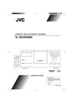
3DMed
3D MEDICAL IMAGE PROCESSING AND ANALYZING SYSTEM
3DMed User Manual
3DMed User Manual Medical Image Processing Group, Institute of Automation, Chinese Academy of Sciences
Web site: http://www.3dmed.net
Corresponding person: Professor Jie Tian
E-mail: [email protected]
3 D M E D
U S E R
M A N U A L
Chapter 1
Overview
3DMed stands for 3D Medical Image Processing and Analyzing System. It is
developed by the Medical Image Processing Group, Institute of Automation, the
Chinese Academy of Sciences. This software system is developed to provide
medical imaging community another available software to process and analyze the
medical image datasets. It is an free software, and can be downloaded from
www.mitk.net freely. In functions, it combines all the functions of Data I/O,
Data Format Converter, 2D Image Processing, Surface Rendering, Volume
Rendering, Image Segmentation, Image Registration, 3D Virtual Cutting and 3D
Measurement. The segmentation and registration functions are provided via the
plugins.
For more details, please visit our web site www.mitk.net.
Main Interface
The main interface of 3DMed is shown in the following figure.
1
3 D M E D
U S E R
M A N U A L
Menu Bar
The “Menu Bar” shows all of the menus of 3DMed, you can click one menu to call
its function. The “Filter”, “Segmentation”, “Registration”, “Visualization” menus
are dynamic menu. And their contents depend on the dynamically loaded plunins.
Tool Bar
The “Tool Bar” provides some frequently used general functions, and you can
access it quickly to click its icon.
Function Buttons and Function Panel
The “Function Buttons” groups the functions provided by 3DMed. Each button
has a corresponding “Function Panel” to provide the user interface to access this
function.
The “Document” button and its panel provide the management of the input data
and the management of the displayed contents in “3D View”.
The “Image Display” button and its panel provide the function of 2D image
processing, please see chapter 2 to get more details.
The “Surface Rendering” button and its panel provide the function of surface
rendering, please see chapter 3 to get more details.
The “Volume Rendering” button and its panel provide the function of volume
rendering, please see chapter 4 to get more details.
The “3D Measurement” button and its panel provide the function of 3dimensional measurement. In this alpha version of 3DMed, this function is not
provided, and it will be provided in later version.
The “3D Cutting” button and its panel provide the function of 3-dimensional
virtual cutting, please see chapter 4 to get more details.
The functions of segmentation and registration are also provided by 3DMed. The
“Segmentation” menu in “Menu Bar” provides the segmentation function. The
system will load segmentation plugins at startup. If there is any segmentation plugin,
a submenu will be added in the menu “Segmentation”. Please see chapter 5 to get
more details about the segmentation functions provide by 3DMed. In this alpha
version of 3DMed, the registration plugins are not provided, so the “Registration”
menu will has no submenu.
3D View
The “3D View” provides a view for displaying the result of surface rendering or
volume rendering, please see chapter 3 and chapter 4 to get more details.
2D Image View
The “2D Image View” provides a view for displaying the medical dataset slice by
slice, please see chapter 2 to get more details.
2
3 D M E D
U S E R
M A N U A L
Status Bar
The “Status Bar” provides a position for displaying some information, for example,
the image value in the mouse position, progress information, etc. Please see chapter
2 to get more details.
Image Input / Output
3DMed supports many formats of data, and new format can be supported by
adding a plugin. To load a medical dataset to 3DMed, you select the menu “File” > “Load Volume”, and several submenus appeared. Each submenu is
corresponding to a supported format in 3DMed. Now 3DMed supports the
loading of “BMP”, “JPEG”, “TIFF”, “DICOM”, “RAW”, “IM0” data files. The
submenus are showed in below.
Also you can left click Document panel , then right click Volumes ,and there will
be the same submenus appeared ,and you can do the samething ,as shown in the
following figure:
3
3 D M E D
U S E R
M A N U A L
When you loaded a dataset to 3DMed,
“Add to view”will display the result with a 3D image in the main window,shown as
following figure.
Before click :
After click :
4
3 D M E D
U S E R
M A N U A L
“Show information”will show some information about the data which has been
loaded, as shown in the following figure:
“Delete” will delete the data which has been loaded , shown in the following figure.
Before click:
5
3 D M E D
U S E R
M A N U A L
After click:
“Remove” will delete the 3D image in the main window , as shown in the
following figure .
Before click :
6
3 D M E D
U S E R
M A N U A L
:
After click:
“3-Dimensional View” will display the result of volume rendering, and “2D Image
View” will display the slices. In the “Document” panel, “New Document” listview
will add a volume in its “Volumes” listitem. It is shown in the following figure:
7
3 D M E D
U S E R
M A N U A L
To save a data in memory to disk, you select the menu “File” -> “Save Volume”,
and several submenus appeared. Each submenu is corresponding to a supported
format in 3DMed. Now 3DMed supports the writing of “BMP”, “JPEG”,
“TIFF”, “DICOM”, “RAW”, “IM0” data files. The submenus are showed in
below.
Image Format Converting
3DMed supports many formats of data, so you can use 3DMed as a image format
converter. You can load a data in the format that 3DMed supports, and save it to a
different format that 3DMed supports. With the adding of new data I/O pulgins,
3DMed will support more and more data formats, and its format converting
function will get more and more applications.
8
3 D M E D
U S E R
M A N U A L
Chapter 2
2D Image Processing
2-Dimensional image processing functions include examining all the slices along zaxis, x-axis and y-axis (X-Y Image, Y-Z image and X-Z Image); playing the slices
continuously; adjusting the window width and window center of the selected
images; displaying the arrow cursor and magnify the area around the center of the
cross; changing the layout of the views.
After loading a volume, click “Image Display” to enter the panel of 2D image
processing functions.
Browsing Slices
In the right-bottom of the main window, there are three kinds of image views of
the volume you can browse shown as follows:
9
3 D M E D
U S E R
M A N U A L
Current selected image view is surrounded by a red rectangle. The controls for slice
location are shown as follows:
Drag the slider to locate the slice of the selected image view. The middle number
below the slider shows the index of current slice. The right number shows the total
number of slices in the selected view.
Press the button “Play” to show the slices continuously. You can control the frame
speed via changing the number in the edit box beside the “Play” button. Press this
button again will stop playing.
Use the combo box to select the volume.
Adjusting Window Width/Center
The controls for adjusting the window width and window center (level) of the slice
in selected image view are shown as follows:
10
3 D M E D
U S E R
M A N U A L
Enter new value into the edit boxes beside label “Width” and label “Level” to
change the window width and window center. Press “Enter” will apply the changes.
11
3 D M E D
U S E R
M A N U A L
Use the combo box to decide whether the changes will apply to all image views or
just selected view.
Press the button “Reset W/L” to reset the window width and center to default
value.
Arrow Cursor
Click the check box to show or hide arrow cursor.
12
3 D M E D
U S E R
M A N U A L
Magnifier
When mouse cursor is moving on the image view, a rectangle area around the
current mouse position of the slice is magnified and shown at the left-bottom of
main window.
Layout Selection
Click the radio button in “Layout Selection” group box to select the layout of the
views (including three image views and one 3-dimensional view).
1*3 layout:
13
3 D M E D
U S E R
M A N U A L
2*2 layout:
14
3 D M E D
U S E R
M A N U A L
Mouse Manipulation for Image View
Parallel movement: Keep left mouse button down and drag on the image view.
15
3 D M E D
U S E R
M A N U A L
Adjusting window width and window center: Keep the middle mouse button
down and drag on the image view. (Vertical movement for window center and
horizontal movement for window width.)
After adjusting:
16
3 D M E D
U S E R
M A N U A L
Zoom: Keep the right mouse button down and drag on the image view.
Zoom in:
Zoom out:
17
3 D M E D
U S E R
M A N U A L
Information in Status Bar
When mouse cursor is moving on the image view, the 3-dimensional coordinates
and RGB value of the mouse cursor’s current position are shown in the status bar
at the bottom of main window.
Tools
18
3 D M E D
U S E R
M A N U A L
Image Tools :
Original image:
19
3 D M E D
U S E R
M A N U A L
Left :will rotate the image that has been chosen to the left with a angle of 90
degrees .result as shown in the following figure
Right:will roate the image that has been chosen to the right with a angle of 90
degrees
Reverse :will reverse the image that has been chosen ,as shown in the following
figure.
20
3 D M E D
U S E R
M A N U A L
Flip : will flip the image that has been chosen ,as shown in the following figure.
Inverse : will inverse the image with black and white .as shown in the following
figure.
Hist : will tell the information about scalar of each point of the current image, as
shown in the following figure.
21
3 D M E D
U S E R
M A N U A L
Widgets
Line :click one time and the bottom is on ,then you can make a line in the image
that you have chosen with the aid of the cross ,and the length of the line will be
shown on the panel ,with the unit of mm.click a second time and the on-bottom is
off ,and then you can choose a line , the line will change it’s color , and then you
make move ,change it’s length ,and even delete to the line .as shown in the
following figure .
22
3 D M E D
U S E R
M A N U A L
Angle:click one time and the bottom is on , the you can make a angle in the image
that you have chosen with the aid of the cross ,and also the degree of the angle will
be shown on the panle ,with the unit of degree ; click a second time and the onbottom is off ,and then you can choose a angle ,the angle will change it’s color ,and
then you can make move ,change it’s degree ,and even delete to the angle, as
shown in the following figure .
Pseudo : click the bottom ,draw a rect ,and the image in the chosen aera will be
transferred from scalar image into RGB image .as shown in the following figure .
23
3 D M E D
U S E R
M A N U A L
Rect : click the bottom , you can make recrangles in the image that you have
chosen with the aid of the cross .as shown in the following figure .
Poly : click the bottom ,you can make polyangles in the image that you have chosen
with the aid of the cross ,as shown in the following figure .
24
3 D M E D
U S E R
M A N U A L
Ellipse : click the bottom ,you can make ellipse in the image that you have chosen
with the aid of the cross ,as shown in the following figure .
25
Chapter 3
Surface Rendering
Surface rendering is a process after segmentation. It will use the result of
segmentation and the source volume data to build a 3-dimensional surface of the
volume, and then render this surface.
In segmentation interface, press “OK” to begin surface reconstruction after
segmentation process has finished. If the reconstruction process is done
successfully, you will see the result in the 3-dimensional view of the main window
as follows.
3 D M E D
U S E R
M A N U A L
Then press “Surface Rendering” button in the left to raise the surface rendering
panel. With this panel and mouse, you can manipulate the rendering of the surface
model.
Rotation, parallel movement and zoom
Keep the left mouse button down and drag on the 3D view to rotate the surface
model freely.
Keep the middle mouse button down and drag on the 3D view to move the
surface model in the scene.
27
3 D M E D
U S E R
M A N U A L
Keep the right mouse button down and drag on the 3D view to make the model
zoom in or zoom out.
Surface select
You can choose different surface from ,and then make transacts to it.
28
3 D M E D
U S E R
M A N U A L
Representation of the model
In the top of panel, three kinds of representation are provided: surface, wire frame
and points.
Surface is the default representation of the surface model shown above. You can
take this as the final result of the surface rendering.
29
3 D M E D
U S E R
M A N U A L
In wire frame representation, all the sides of triangles of the surface will be shown
in the scene. (The result is magnified.)
In points representation, all the vertices of the surface model will be shown in the
scene. (The result is magnified.)
30
3 D M E D
U S E R
M A N U A L
If the surface model is very big, it will take long time to render in surface
representation and mouse responses will be very slow. In this condition, you can
do mouse manipulation (rotation, parallel movement and zoom) in points
representation and see the result in surface representation.
Interpolation modes
31
3 D M E D
U S E R
M A N U A L
There are two interpolation modes in surface representation: flat and smooth. In
wire frame and points representation, the selection of interpolation modes is
disabled.
Flat interpolation mode uses a simple interpolation method to render the surface.
Compared with smooth mode, the result is rough but the rendering process is a
little faster.
Smooth interpolation mode uses a complicated interpolation method to render the
surface. The result is smooth but the speed is slow..
32
3 D M E D
U S E R
M A N U A L
Material properties
In this area, you can adjust the material (color) properties of the surface model.
From the menu ,you can choose different objects ,such as default ,bone ,skin and
muscle ,and then make transacts to it .
In surface representation, you can adjust ambient color, diffuse color, specular
color, emission color, specular power and opacity of the surface. To adjust color,
click the radio button of the color you want to adjust, and then drag the slider
beside “Red”, “Green”, “Blue” or “Alpha” to change the value of each channel.
You can also enter the value directly into the edit box to change the value (between
0.0 and 1.0). Focus leave the edit box or “Enter” is pressed will apply the changes.
The way to adjust specular power and opacity is the same as above.
33
3 D M E D
U S E R
M A N U A L
If the value of opacity is below 1.0, the result will be translucent.
34
3 D M E D
U S E R
M A N U A L
Note:
i. The value of specular power is between 0.0 and 128.0;
ii. The value of opacity is the same as the alpha value of diffuse color and these two value will
be changed together.
In wire frame representation, you can adjust the edge color and line width. (The
result is magnified.)
35
3 D M E D
U S E R
M A N U A L
In points representation, you can only adjust the size of point. The color of points
is decided by the surface materials. (The result is magnified.)
36
3 D M E D
U S E R
M A N U A L
Background Color
Click this bottom ,and you can select a background color for the main window. As
shown in the following figure .
Original background :
37
3 D M E D
U S E R
M A N U A L
Chosen background:
38
3 D M E D
U S E R
M A N U A L
Reverse Normals
It is a tool to correct the wrong direction of the normals calculated by the
reconstruction algorithm. Sometimes the direction is opposite to the right direction
and results in an abnormal display. You can press this button to get a proper
display.
One abnormal display:
39
3 D M E D
U S E R
M A N U A L
The proper display after reversed the normals:
40
Chapter 4
Volume Rendering
Volume rendering is a process to render a volume to an image directly. When you
loaded a volume into 3DMed, the result of volume rendering will be display in the
“3-Dimensional View” automatically. You can control and manipulate the process
of volume rendering in various ways.
Rotation, translation and zooming
Keep the left mouse button down and drag on the 3D view to rotate the volume
rendered image freely. See the following figure for a rotated image.
3 D M E D
U S E R
M A N U A L
Keep the middle mouse button down and drag on the 3D view to translate the
volume rendered image in the scene. See the following figure for a translated image.
Keep the right mouse button down and drag on the 3D view to make the model
zoom in (mouse move up) or zoom out (mouse move down). See the following
figures for zoomed images.
(Zoom in )
42
3 D M E D
U S E R
M A N U A L
(Zoom out )
Selection of Transfer Function
To select the transfer function, click the “Volume Rendering” button in the
“Function Buttons”. This will bring the volume rendering panel to the front panel
in the “Function Panel”. The volume rendering panel is shown in the following
figure:
43
3 D M E D
U S E R
M A N U A L
In the volume rendering panel, there are two tabs. One is “Transfer Function”, and
the other is “Shading”. To select the transfer function, click the “Transfer
Function” tab. The tab is shown in the following figure:
44
3 D M E D
U S E R
M A N U A L
In this tab, you can select the scalar-opacity, scalar-color, gradient-opacity transfer
functions. Each transfer function has some preset for choice. For example,
“Scalar-Color Transfer Function” provides two preset for the user choice. They are
“Gray scale” and “Rainbow”. If you select “Gray scale”, the volume rendered
image will be a gray image, as is shown in the following figure:
45
3 D M E D
U S E R
M A N U A L
And if you select “Rainbow”, the volume rendered image will be a color image, as
is shown in the following figure:
Control of shading parameters
To control the shading parameters, click the “Shading” tab in the volume rendering
panel. The tab is shown in the following figure:
46
3 D M E D
U S E R
M A N U A L
The “Enable Shading” check box is used to control if the shading is calculated. If
you check this option, then the shading calculation is took effect. Otherwise, there
is no shading calculation in the volume rendering process. When the shading is
turned on, you can control the shading parameters by setting the ambient, diffuse,
specular, power, or by selecting a preset material from the “Preset Material” listbox.
Cutting of Volume Rendered Image
To cut or clip a volume rendered image, click the the “3D Cutting” button in the
“Function Buttons”. This will bring the 3d cutting panel to the front panel in the
“Function Panel”. The 3d cutting panel is shown in the following figure:
47
3 D M E D
U S E R
M A N U A L
The “Enable Clipping” check box is used to control if the cutting (clipping) is
enabled. If you check this option, then the cutting (clipping) is took effect.
Otherwise, there is no cutting (clipping) in the volume rendering process. When
the cutting (clipping) is turned on, the “Plane Clipping” and “Cube Clipping” radio
button is enabled. You can turn “Plane Clipping” on, turn “Cube Clipping” on, or
turn both on.
When the “Plane Clipping” is turned on, you can add a clipping plane by click the
“Add” button. The initial direction can be selected in the “Initial Direction” listbox.
The following figure show a “YoZ” plane clipped image.
When the “Cube Clipping” is turned on, you can control the size of the cube by
adjusting the slider position of “Left”, “Right”, “Bottom”, “Top”, “Front” and
“Back” slider. The “Reserve Cube” and “Cut Cube” in the listbox are used to
control which part is cutted. The following figure show a “Reserve” cube clipped
image, the part of the specified cube is reserved.
The following figure show a “Cut” cube clipped image, the part of the specified
cube is cutted.
48
3 D M E D
U S E R
M A N U A L
49
3 D M E D
U S E R
M A N U A L
Chapter 5
Segmentation
After loading the volume, you can click the “Segmentation” item in the main menu
to begin the segmentation process. There are several items in the submenu of
“Segmentation”. Each of them represents a different segmentation method.
Threshold Segmentation
Click the “Threshold Segmentation” item in the “Segmentation” submenu, and
then you can begin the threshold segmentation process.
50
3 D M E D
U S E R
M A N U A L
After the “Threshold Segmentation” item is clicked, there will appear a dialog and
you can proceed the threshold segmentation in this dialog.
There two images on the top of the dialog. The left image is the “source image”
which represents the original image before segmentation. The right image is the
51
3 D M E D
U S E R
M A N U A L
“destination image” which represent the result image after segmentation. The
“Column Diagram” is in the middle of the dialog. It shows you the pixel
information of the original image. The “Slice Number Slide” is on the bottom of
the dialog. You can use it to change the current slide number among the volume.
You can drag the left or right arrow below the “Column Diagram” to select your
interest area.
The left arrow changes the “Low Thresh” value and the right arrow changes the
“High Thresh” value. After you change these values, the “Destination Image” will
show you the result after segmentation.
52
3 D M E D
U S E R
M A N U A L
If you are satisfied with the result and want to save it, click the “OK” button to
close the dialog, otherwise you can click the “Cancel” button to close the dialog
without saving the result of the segmentation.
53
3 D M E D
U S E R
M A N U A L
Interactive Segmentation
Click the “Interactive Segmentation” item in the “Segmentation” submenu, and
then you can begin the interactive segmentation process.
After the “Interactive Segmentation” item is clicked, there will appear a dialog
and you can proceed the Interactive segmentation in this dialog.
54
3 D M E D
U S E R
M A N U A L
There two images on the top of the dialog. The left image is the “source image”
which represents the original image before segmentation. The right image is the
“destination image” which represents the result image after segmentation. The
“Slice Number Slide” is on the bottom of the dialog. You can use it to change the
current slide number among the volume.
You can select your interest area in the “Source Image” by drawing a polygon.
You can begin drawing the polygon by clicking the left button of your mouse on a
point of the “Source Image”. And the point will become the first point of your
polygon. Select the second point by clicking on left button of your mouse on
another point in the “Source Image”. The same is to the third and forth point of
your polygon…
55
3 D M E D
U S E R
M A N U A L
When you want to end the polygon, click the right button of your mouse. It will
automatically link the last point to the first point to form a polygon. And the inter
area of the polygon will be segmented. The result of the segmentation will be
showed in the “Destination Image”.
56
3 D M E D
U S E R
M A N U A L
You have to segment the volume slice by slice. Use the “Slice Number Slide ” to
change the current slice. When you finish segmenting the whole volume, click the
“OK” button to save the segmentation result and close the dialog. Click the
“Cancel ” button to close the dialog without saving the result.
Fast Marching Segmentation
Click the “Fast Marching Segmentation” item in the “Segmentation” submenu,
and then you can begin the Fast Marching segmentation process.
57
3 D M E D
U S E R
M A N U A L
After the “Fast Marching Segmentation” item is clicked, there will appear a
dialog and you can proceed the Fast Marching segmentation in this dialog.
There two images on the top of the dialog. The left image is the “source image”
which represents the original image before segmentation. The right image is the
58
3 D M E D
U S E R
M A N U A L
“destination image” which represents the result image after segmentation. The
“Slice Number Slide” is on the bottom of the dialog. You can use it to change the
current slide number among the volume.
First, you should define the stop value by enter it into the “Stop Value” text edit.
Then check the “Fast Marching Segmentation” check button to tell the computer
that you are going to proceed the segmentation. Click the left button of your
mouse on one point of your interest area in the “Source Image”, the result of your
segmentation will be showed in the “Destination Image”.
You can also click the left button of your mouse on the point of your another
interest area. The result of the previous segmentation will be accumulated.
59
3 D M E D
U S E R
M A N U A L
If you are not satisfied with the result, click the “Clear Result” button, the
segmentation result will be cleared, and the “destination image” return to the
original one.
Note that the segmentation is carried out in 3 dimensions. When you finished the
segmentation, you can click the “OK” button to save the result and close the
60
3 D M E D
U S E R
M A N U A L
dialog. You can also close the dialog without saving the result by clicking the
“cancel” button.
61