1
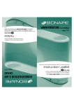
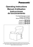
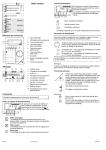
USER MANUAL
LX 420, 421
Table of contents
English ...................................................... 2
Français .................................................... 5
088L3353 - 01.01
57470
Product program
This user manual covers following thermostats with built-in GFCI
LXstat-420
Incl. floor sensor 3m
LXstat-421
With built-in room
sensor
between the two set points is easily done
with one push at the OK ( ) button.
Introduction
The thermostat is an electronic on/off thermostat for control of temperature by means
of an NTC sensor either placed externally
or internally in the thermostat. The thermostat has integrated a Ground Fault Circuit
Interrupter (GFCI, Class A). The thermostat
and the GFCI is a dual model suitable for
120/240 V 50/60 Hz supply.
The thermostat has a pin button marked R,
allowing you to reset the thermostat to factory settings. These are listed at the end of
this manual with space for you to record your
settings.
The temperature can be displayed in eigher
°C or in °F. Switching can be done on the pin
button marked with ( )
The thermostat type LXstat-420 has an
external temperature sensor that is normally
placed in the floor construction. In this configuration the thermostat
controls the temperature of the floor and
not the temperature within the room. The
thermostat type LXstat-421 has a built-in
temperature sensor. In this configuration the
thermostat controls the temperature of the
room.
The thermostat has two adjustable set
points, one for the day operation and one
for the night setback temperature. Switching
1. Getting started
Buttons
A
I
B
H
C
G
D
F
E
2
A:
B:
C:
D:
E:
F:
G:
H:
I:
Reset of GFCI
Red light indicating ground fault
Test of GFCI
Pin button ºC / ºF
Display
Reset to factory setting
Adjustment down
OK - accept
Adjustment up
Display symbols
J: Clock function
J
Wake
Night
K: Heating on
K
Setting the thermostat into operation
Actual temperature setting is shown in the display and the thermostat is ready for use.
Comfort mode
To change the temperature press UP ( ) or
DOWN ( ) to increase or decrease the temperature. The display will flash for 5 seconds, and will
then show the new temperature setpoint.
To jump between the two set points press the OK (
) button
Night, Setback
temperature
To change the temperature press UP ( ) or
DOWN ( ) to increase or decrease the temperature. The display will flash for 5 seconds, and will
then show the new temperature setpoint.
OFF
To turn the thermostat OFF, press DOWN (
OFF appears in the display.
) until
DO NOT USE THE TEST BUTTON ON THE GFCI
TO SWITCH OFF THE HEATING INSTALLATION.
The GFCI will automatically be reset after a disconnection of the mains supply
3
Checking GFCI
It is important that the GFCI has been
checked for correct installation and function.
the display will return to normal appearance.
If the test fails, check your heating cable and
the thermostat. The GFCI test should be carried out monthly.
To check the GFCI: Testing can only be
performed if the thermostat has a heating demand. Adjust the set point until the
heating symbol (SSS) appears, use the ( ),
to increase the heating demand. Wait 10
secs. to let the thermostat work according to
the new set point. Press the button “TEST”.
The test is conclusive if the red light on the
thermostat lightens, and the display signs
disappear. If this does not occur, check the
installation. Press on RESET button to reset
the GFCI. The red light should disappear and
If the GFCI trips in normal operation, without
pressing the TEST button, there could be a
ground fault! To check whether it is a ground
fault or a nuisance tripping, press RESET. If
this cause the red light to shot off and not
comes on again, it was a nuisance tripping
and the system is functioning. If this cannot
be done there is a ground fault! Check your
heating cable, the sensor cable and the thermostat. Exchange the defective part.
3. Reset to factory setting
Press the pin button for 3 secs. and the thermostat returns to factory
settings.
Factory settings
SCALE
With floor sensor
Built-in sensor
77˚F / 25˚C
68˚F / 20˚C
68˚F / 20˚C
59˚F / 15˚C
˚F
˚F
4. Failure codes
E0 = Internal failure, replace thermostat
E1 = Built-in sensor short-circuit or disconnected, replace thermostat
E2 = External sensor short-circuit or
disconnected
5. Technical data
Supply: 120/240 Vac 50/60 Hz
Load:
16A maximum (resistive load)
Power: 1.920 W at 120 Vac
3.840 W at 240 Vac
GFCI:
Class A (5 mA trip level)
4
Temperature range:
+5 to +40°C,
+40 to +104˚F
Amb. Temperature range:
Thermostat:
0 to +40°C,
+32 to +104˚F
GFCI:
-35 to +65°C,
-31 to +149˚F
Programmation du produit
Ce guide d’utilisation contient des renseignements sur les modèles de thermostat avec
disjoncteur de fuite à la terre intégré.
LXstat-420
avec capteur de
plancher 3 m
LXstat-421
avec capteur de pièce
Introduction
Le thermostat est du type électronique à
action par tout ou rien qui régule la température au moyen d’un capteur NTC placé soit
à l’extérieur, soit à l’intérieur du thermostat.
Il est doté d’un disjoncteur de fuite à la terre
(GFCI de classe A). Le thermostat et le GFCI
sont compatibles aux modes d’alimentation
120/240 V 50/60 Hz.
ment de jour et un pour la nuit. Pour passer
d’un point de consigne à l’autre, il suffit
d’appuyer une fois sur la touche OK ( ).
Il est possible d’afficher la température en
degrés Celsius ou Fahrenheit. Pour passer
d’une unité à l’autre, il suffit d’appuyer sur le
bouton miniature identifié du symbole ( ).
Le thermostat dispose d’un bouton miniature
identifié d’un R qui vous permet de le réinitialiser aux réglages de l’usine. Ces réglages
sont énumérés à la fin de ce guide.
Le modèle de thermostat LXstat-420
est muni d’un capteur de température
externe que l’on place normalement dans
le plancher. De cette façon, le thermostat
contrôle la température du plancher et non
celle de la pièce.
Le modèle de thermostat LXstat-421 est
doté d’un capteur de température intégré.
Dans cette configuration, le thermostat contrôle la température de la pièce.
Le thermostat dispose de deux points de
consigne réglables: un pour le fonctionne1. Début
Touches
A
I
B
H
C
G
D
F
A: Réinitialisation du disjoncteur de fuite à
la terre
B: Voyant rouge indicateur de mise à la
masse défectueuse
C: Vérification du disjoncteur de fuite à la
terre
D: ºC / ºF
E: Affichage
F: Remise aux réglages effectués en usine
G: Ajustement vers le bas
H: OK - acceptation
I: Ajustement vers le haut
E
5
Symboles de l’affichage
J
J: Symboles des événements:
Éveil
Nuit
K: Chauffageen circuit
K
Activation du thermostat
Le point de consigne de température actuel est affiché et le thermostat est prêt à être
utilisé.
2. Usage quotidien du thermostat
Mode confort
Pour modifier la température, appuyez sur les
touches de défilement vers le haut ( ) ou vers le
bas ( ), respectivement, pour élever ou abaisser
la température.
L’affichage clignotera pendant cinq secondes,
puis indiquera le nouveau point de consigne de
température.
Pour passer d’un point de consigne à l’autre, appuyez sur la touche OK (
6
).
Température de
nuit
Pour modifier la température, appuyez sur les
touches de défilement vers le haut ( ) ou vers le
bas ( ) , respectivement, pour élever ou abaisser
la température.
L’affichage clignotera pendant cinq secondes,
puis indiquera le nouveau point de consigne de
température.
Désactivation
Pour désactiver le thermostat, appuyez sur la
touche de défilement vers le bas ( ) jusqu’à ce
que le témoin « OFF » s’affiche.
N’UTILISEZ PAS LA TOUCHE D’ESSAI DU
DISJONCTEUR DE FUITE À LA TERRE POUR
DÉSACTIVER L’INSTALLATION DE CHAUFFAGE.
Le disjoncteur de fuite à la terre se réinitialisera
automatiquement par suite d’une coupure de
l’alimentation secteur.
Vérification du disjoncteur de fuite à la
terre (GFCI)
Il est important de vérifier l’installation et le
fonctionnement du disjoncteur de fuite à la
terre.
la terre. Le voyant rouge devrait s’éteindre
et l’affichage revenir à la normale. Si le test
échoue, vérifiez le câble chauffant et le thermostat. Le test du disjoncteur de fuite à la
terre devrait être effectué mensuellement.
Test du disjoncteur: Pour vérifier le fonctionnement du disjoncteur, il faut qu’il y ait
une demande de chauffage au thermostat.
Réglez le point de consigne au thermostat
jusqu’à ce que le symbole de chauffage
(SSS) s’affiche. Servez-vous de la touche
( ) pour augmenter la demande de chauffage. Patientez dix secondes pour laisser le
thermostat s’adapter à la nouvelle demande,
puis appuyez sur la touche TEST. L’essai est
concluant si le voyant rouge du thermostat
s’allume et que les signes sur l’affichage
disparaissent. Dans le cas contraire, vérifiez
l’installation. Appuyez sur la touche RESET
pour réenclencher le disjoncteur de fuite à
Si le disjoncteur se déclenche en mode
de fonctionnement normal, sans qu’il soit
nécessaire d’appuyer sur la touche TEST,
cela pourrait indiquer la présence d’une mise
à la terre défectueuse. Pour vérifier s’il s’agit
d’une mise à la terre défectueuse ou d’un
déclenchement intempestif, appuyez sur la
touche de réenclenchement (RESET). Si le
voyant rouge s’éteint et qu’il ne se rallume
pas, il s’agissait d’un déclenchement intempestif et le système fonctionne correctement.
Dans le cas contraire, il y a effectivement une
mise à la terre défectueuse ! Vérifiez le câble
chauffant, le câble du capteur et le thermostat, puis remplacez la pièce défectueuse.
3. Remise aux réglages effectués en usine
Appuyez sur le bouton miniature pendant trois secondes et le thermostat reviendra aux réglages effectués en usine.
Réglage en usine
Échelle
Avec capteur de
plancher
Capteur intégré
77˚F / 25˚C
68˚F / 20˚C
68˚F / 20˚C
59˚F / 15˚C
˚F
˚F
7
4. Codes de dérangement
E0 = Défectuosité interne; remplacez le
thermostat
E1 = Capteur interne court-circuité ou
déconnecté; remplacez le
thermostat
E2 = Capteur externe court-circuité ou
déconnecté
5. Fiche technique
Source d’alimentation
Charge
Puissance
GFCI:
Plage de témperature
120/240 V
c.a.50/60 Hz
16A maximum
(charge résistive)
1.920 W à 120 V c.a.
3.840 W à 240 V c.a.
Classe A
(seuil e déclenchement réglé à 5 mA)
+5 à +40°C,
+40 to +104˚F
Plage de témperature ambiante:
Thermostat:
de 0 à +40°C,
+32 à +104˚F
GFCI:
-35 à +65°C,
-31 à +149˚F
Danfoss can accept no responsibility for possible errors in catalogues, brochures and other printed material. Danfoss reserves the right to alter its products without notice. This also applies to
products already on order provided that such alterations can be made without subsequential changes being necessary in specifications already agreed.
All trademarks in this material are property of the respective companies. Danfoss and the Danfoss logotype are trademarks of Danfoss A/S. All rights reserved.
Danfoss A/S
DK-6430 Nordborg
Denmark
Tel.: +45 74 88 22 22
Telefax: +45 74 49 09 49
E-mail: [email protected]
8