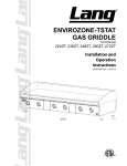
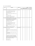
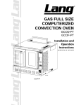
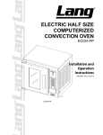
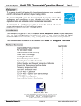
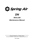
1
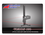
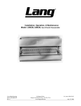
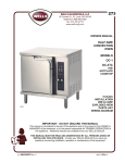
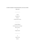
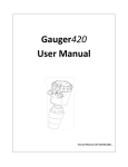
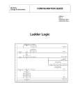
GAS CHARBROILER Installation and Operation Instructions 2M-W1649 Rev. A 4/07/11 IL1883a WARNING: Improper installation, adjustment, WARNING: This appliance shall be installed FOR YOUR SAFETY: Do not store or use In addition, there should be posted, in a prominent location, detailed instructions to be followed in the event the operator smells gas. Obtain the instructions from the local gas supplier. alteration, service or maintenance can cause property damage, injury or death. Read the installation, operating and maintenance instructions thoroughly before installing or servicing this equipment. in accordance with current regulations and used only in well-ventilated space. Refer to instructions before installing and using this appliance. gasoline or other flammable vapors or liquids in the vicinity of this or any other appliance. Retain This Manual for Future Reference. 1 SAFETY SYMBOL These symbols are intended to alert the user to the presence of important operating and maintenance instructions in the manual accompanying the appliance. FOR YOUR SAFTEY DO NOT STORE OR USE GASOLINE OR OTHER FLAMMABLE VAPORS AND LIQUIDS IN THE VICINTIY OF THIS OR ANY OTHER APPLIANCE. The installation of the Appliance must conform to the NATIONAL FUEL GAS CODE "ANSI Z223.1 - LATEST EDITION" AND ALL LOCAL GAS COMPANY RULES AND REGULATIONS. IN CANADA INSTALLATION SHALL BE IN ACCORDANCE WITH THE CURRENT CAN/CGA-B149.1 NATURAL GAS INSTALLATION CODE OR CAN/CGA-B149.2 PROPANE INSTALLATION CODE AND LOCAL CODES WHERE APPLICABLE. POST IN PROMINENT LOCATION INSTRUCTIONS TO BE FOLLOWED IN THE EVENT USER SMELLS GAS. THIS INFORMATION SHALL BE OBTAINED BY CONSULTING YOUR LOCAL GAS SUPPLIER. AS A MINIMUM, TURN OFF THE GAS AND CALL YOUR GAS COMPANY AND YOUR AUTHORIZED SERVICE AGENT. EVACUATE ALL PERSONNEL FROM THE AREA. WARNING IMPROPER INSTALLATION, ADJUSTMENT, ALTERATION, SERVICE OR MAINTENANCE CAN CAUSE PROPERTY DAMAGE, INJURY OR DEATH. READ THE INSTALLATION, OPERATION & MAINTENANCE INSTRUCTIONS THOROUGHLY BEFORE INSTALLING OR SERVICING THIS EQUIPMENT. WARNING RISK OF FIRE OR ELECTRIC SHOCK DO NOT OPEN WARNING, TO REDUCE THE RISK OF ELECTRICAL SHOCK, DO NOT REMOVE CONTROL PANEL. NO USER-SERVICABLE PARTS INSIDE. REPAIRS SHOULD BE DONE BY AUTHORIZED SERVICE PERSONNEL ONLY. NOTICE Using any part other than genuine Lang factory supplied parts relieves the manufacturer of all liability. Lang reserves the right to change specications and product design without notice. Such revisions do not entitle the buyer to corresponding changes, improvements, additions or replacements for previously purchased equipment. Due to periodic changes in designs, methods, procedures, policies and regulations, the specifications contained in this sheet are subject to change without notice. While Lang Manufacturing exercises good faith efforts to provide information that is accurate, we are not responsible for errors or omissions in information provided or conclusions reached as a result of using the specications. By using the information provided, the user assumes all risks in connection with such use. MAINTENANCE AND REPAIRS Contact your local dealer for service or required maintenance. Please record the model number, serial number, voltage and purchase & Installation Information in the area below and have it ready when you call to ensure a faster service. Model No.: Purchased From: Serial No.: Location: Voltage: Purchase Date: 1-Phase or 3 Phase: Installed Date: 22 PROBLEMS, QUESTIONS or CONCERNS Before you proceed consult you authorized Lang service agent directory or Call the Lang Technical Service & Parts Department at 314-678-6315. TABLE OF CONTENTS Specifications . . . . . . . . . . . . . . . . . . . . . . . . . . . . . .4 Equipment Description . . . . . . . . . . . . . . . . . . . . . . . . . 5 General Installation Data Exhaust Canopy. . . . . . . . . . . . . . . . . . . . . . . . . . .6 Air Supply . . . . . . . . . . . . . . . . . . . . . . . . . . . . . .6 Leveling Unit. . . . . . . . . . . . . . . . . . . . . . . . . . . . 7 Placing Radiants - RCB Series . . . . . . . . . . . . . . . . . . .8 Gas Piping. . . . . . . . . . . . . . . . . . . . . . . . . . . . . .8 Manual Shut-Off Valve . . . . . . . . . . . . . . . . . . . . . . . 8 Connecting Gas Supply Line . . . . . . . . . . . . . . . . . . . . 8 Propane Gas Conversion . . . . . . . . . . . . . . . . . . . . . .8 Checking for Gas Leaks. . . . . . . . . . . . . . . . . . . . . . .8 Pilot Lighting Instructions . . . . . . . . . . . . . . . . . . . . . .9 Burner Ignition & Adjustment . . . . . . . . . . . . . . . . . . . . 9 General Operating Instructions Water Pan. . . . . . . . . . . . . . . . . . . . . . . . . . . . . Burner Operation . . . . . . . . . . . . . . . . . . . . . . . . . . Lighting . . . . . . . . . . . . . . . . . . . . . . . . . . . . . . . Broiling . . . . . . . . . . . . . . . . . . . . . . . . . . . . . . . Tilting the Grate. . . . . . . . . . . . . . . . . . . . . . . . . . Shutting Down Instructions. . . . . . . . . . . . . . . . . . . . . Cleaning. . . . . . . . . . . . . . . . . . . . . . . . . . . . . . 10 10 10 10 10 10 10 Exploded View & Parts List . . . . . . . . . . . . . . . . . . . . . 11 - 17 NOTICE Service on this or any other Lang appliance must be performed by qualified personnel only. Consult your Lang Authorized Service Agent Directory. You can call our toll free number 314-678-6315 or visit our website www.langworld.com for the service agent nearest you. 3 SPECIFICATIONS ELECTRICAL CONNECTION 5 1/2 FT CORD 3 3/16" (81) 3" (77) 36" (913) 23" (584) 16 5/8" (422) IL1826a 4" (102) 4" (102) Top View/Plan Front View/Elevation EQUIPMENT SPECIFICATIONS GAS CHEFSERIES CHARBROILER Model 2124ZRCB 2136ZRCB 2148ZRCB 2160ZRCB 2172ZRCB Height x Width x Depth Clearance from (Not Including legs) combustible surface* Weight Actual Shipping 10-58” X 24” X 28-5/8” 165 lbs. 200 lbs. 422mm x 610mm x 727mm 75 kg 91 kg 10-5/8” x 36” x 28-5/8” 225 lbs. 265 lbs. 422mm x 914mm x 727mm 102 kg 120 kg 300 lbs 285 lbs 136 kg 130 kg 10-5/8” x 60” x 28-5/8” 385 lbs. 430 lbs. 422mm x 1524mm x 727mm 175 kg 195 kg 10-5/8” x 72” x 28-5/8” 470 lbs 520 lbs 422mm x 1829mm x 727mm 214 kg 236 kg 10-5/8” x 48” x 28-5/8” 422mm x 1219mm x 727mm Sides & Back: 4” * Noncombustible floor only Model Gas Requirement (3/4” NPT) 2124ZRCB 64,000 BTU/hr 2136ZRCB 96,000 BTU/hr 2148ZRCB 128,000 BTU/hr 2160ZRCB 160,000 BTU/hr 2172ZRCB 192,000 BTU/hr 4 Fright Class 65 65 65 65 65 EQUIPMENT DESCRIPTION Lighting Instructions On/Off Switch Hinged Front Panel 12” Section Knob 4” Adj. Legs Standard (Legs & Casters Optional) Grease Pan Grates Grease Trough Front IL1884 Power Cord Nameplate Gas Inlet 5 Wall Mounting GENERAL INSTALLATION DATA CAUTION This equipment is designed and sold for commercial use only by personnel trained and experienced in its operation and is not sold for consumer use in and around the home nor for use directly by the general public in food service locations. The Lang series gas charbroiler is equipped for the type of gas indicated on the nameplate mounted on the front panel. All units are shipped from the factory for use with natural gas. The unit can easily be converted for use with propane gas: see propane gas. -IMPORTANTBe sure to remove all paper protection and packing material from unit prior to lighting. INSTALL IN NON-COMBUSTIBLE LOCATIONS ONLY! Clearance from noncombustible construction must be 4" minimum from back and sides. For servicing, 6" is recommended from back of unit. The installation of the Appliance must conform to the NATIONAL FUEL GAS CODE "ANSI Z223.1 - LATEST EDITION" AND ALL LOCAL GAS COMPANY RULES AND REGULATIONS. IN CANADA INSTALLATION SHALL BE IN ACCORDANCE WITH THE CURRENT CAN/CGA-B149.1 NATURAL GAS INSTALLATION CODE OR CAN/CGA-B149.2 PROPANE INSTALLATION CODE AND LOCAL CODES WHERE APPLICABLE. NOTICE When this appliance is installed with casters, it must be installed with the casters supplied, a connector complying with either ANSI Z21.69 or CAN/CGA-6.16 and a quick-disconnect device complying with either ANSI Z21.41 or CAN1-6.9. It must also be installed with restraining means to guard against transmission of strain to the connector, as specified in the appliance manufacturer's instructions. For your protection, we recommend a qualified installing agency install this appliance. They should be familiar with gas installations and your local gas requirements. In any case, your gas company should be called to approve the final installation. This appliance, its pressure regulator and its individual shutoff valve must be disconnected from the gas supply piping system during any pressure testing of that system at test pressures in excess of 1/2 PSIG. This appliance and its pressure regulator must be isolated from the gas supply piping system by closing its individual manual shutoff valve during any pressure testing of the gas supply piping system at test pressures equal to or less than 1/2 PSIG. EXHAUST CANOPY Open hearth broilers inherently create a good deal of heat and smoke and should be installed under an efficient exhaust hood with flame proof filters. A vertical distance of not less than 48" shall be provided between the top of the appliance and filters or any other combustible material. Exhaust installation must conform to local codes. AIR SUPPLY Provisions for adequate air supply must be provided. CAUTION Air for combustion enters from the bottom of the unit. Do not obstruct this area. 6 GENERAL INSTALLATION DATA (continued) LEVELING UNIT This charbroiler is supplied with 4 feet or floor stand legs which must be screwed into the body. Unit must be level. Level unit by adjusting the (4) feet which have an adjustment of 1-3/4" for accurate and perfect line-up with other units. CAUTION DO NOT INSTALL WITHOUT ATTACHING FEET OR SUPPLIED STAND LEGS AND SHELF - DO NOT REMOVE FEET. IL1887a Model 2124ZRCB with tall legs. Tall legs and casters are optional. 7 GENERAL INSTALLATION DATA (continued) PLACING RADIANTS After the unit is unpacked and installed, place 1 radiant above each burner. Install each radiant on 2 slots of the rear wall and on the 2 pins of the front wall of the liner weld assembly. Refer to the exploded view in this manual for orientation of the radiants. GAS PIPING Gas piping shall be of such size and so installed as to provide a supply of gas sufficient to meet the full gas input of the appliance. If the appliance is to be connected to existing piping, it shall be checked to determine if it has adequate capacity. Joint compound shall be used sparingly and only on the male threads of the pipe joints. Such compounds shall be resistant to the action of L.P. gases. WARNING: Any loose dirt or metal particles which are allowed to enter the gas lines on this appliance will damage the valve and affect its operation. When installing this appliance, all pipe and fittings must be free from all internal loose dirt.. MANUAL SHUT OFF VALVE VENT SUPPLIED REGULATOR A manual shut off valve should be installed upstream from the manifold and within six feet of the charbroiler. OW FL CONNECTING GAS SUPPLY LINE The gas inlet of the charbroiler is sealed at the factory to prevent entry of dirt. Do not remove this seal until the actual connection is made to the gas supply line. GAS SHUT-OFF VALVE* BA CK OF UN IT DRIP LEG* PROPANE GAS - CONVERSION GAS This charbroiler is equipped with fixed * by others IL1828a SUPPLY* orifice hoods and is shipped from the factory for use with natural gas. To convert to propane gas, install the burner orifice hoods, located in the water pan, as follows: 1. 2. 3. 4. Remove grates, radiants and burners. Remove the burner orifice hoods and install the orifice hoods supplied. Replace the burners, radiants, and grates. Set manifold pressure to (10) inch water column. A 1/8" pipe plug on the burner manifold can be removed for attaching a pressure gauge. Remove the slotted, or hex-threaded plug from the pressure regulator. Invert the plug and re-install. The letters "LP" should now be visible on the plug. The regulator is now set for 10" (25.4 cm) water column. Attach the conversion label, supplied with the unit, close to the nameplate. CHECKING FOR GAS LEAKS Check entire piping system for leaks. Soap and water solution or other material acceptable for the purpose, shall be used in locating gas leakage. CAUTION Matches, candle flame or other sources of ignition shall not be used for locating gas leaks. 8 GENERAL INSTALLATION DATA (continued) PILOT LIGHTING INSTRUCTIONS The charbroiler is equipped with an automatic pilot/ignter with an electronic spark. Be sure all gas control knobs on the units front panel are turned OFF. Turn on main gas supply valve to unit. Turn "ON" the switch on front control panel to activate electonic pilot lighter. The pilot igniter tubes on this broiler have been pre-set at the factory. Turn the adjustable screw counterclockwise to open and clockwise to close. 5. Adjust pilot light flames, if necessary as small as possible, usually about 3/8" high, but high enough to light burner immediately when burner valve is turned on high. 6. Turn burner knobs to desired setting. 7. To turn burners off, turn knobs off and turn off switch on front control panel. 1. 2. 3. 4. BURNER IGNITION AND ADJUSTMENT 1. To ignite burners turn burner valve knob counter clockwise to "ON"position. 2. Slowly decrease openings of air shutters to give a soft blue flame having luminous tips, then slowly increase openings to a point where the yellow tips disappear and a hard blue flame is obtained. DO NOT ATTEMPT TO OPERATE UNIT DURING A POWER FAILURE. 9 GENERAL OPERATING INSTRUCTIONS WATER PAN The water pan is located at the bottom of the unit, and is easily removed from the front of the unit. Water should be added to the water pan to just cover bottom and replaced as necessary. The water pan helps prevent flare ups and catches grease. Keep Water Pan filled with water to Prevent Flare-ups IL2223 BURNER OPERATION Each burner is controlled by an individual high-low, on-off valve. A variety of broiling temperatures may be obtained by turning the burner valve knob to any position between ON and LO. It is possible through this arrangement to have a high heat or searing section, while having a low heat finishing or holding section. For the searing operation, turn the valve counter clockwise for the section to a position of "ON" or close to it. For holding or finishing, turn the valves closer to the "LO" position on the dial. You select the heat pattern you like, and set the valves accordingly. Be sure burners are staying fully lit when set in low positions. LIGHTING When broiler is first lit, it will smoke for approximately 20-30 minutes until the preservation OILS and impurities are burned off. BROILING Turn valves on and pre-heat unit on "ON" before attempting to broil. You will have to experiment with the grate settings and the valve settings for your particular food products. Check water pans frequently and add a sufficient amount of water when necessary. Hot water vapors rising from the water pans and through the combustion chamber helps reduce flare ups. Exercise care when using your broiler. TILTING THE GRATE Raise or lower the grate to the next step by lifting the grate at the back of the charbroiler where the grate rests. Use potholders or gloves to reposition. CAUTION CHARBROILERS ARE HOT! NEVER ATTEMPT TO CHANGE THE GRATE POSITION WHILE FOOD PRODUCTS ARE COOKING. FLARE UPS CAN OCCUR UNEXPECTEDLY. TURN OFF CHARBROILER, AND ALLOW THE CHARBROILER TO COOL. SHUTTING DOWN INSTRUCTIONS Turn "OFF" the pilot lighting switch on the front panel and put the burner valve knobs to the off position to turn burners off and close manual valve gas shutoff. CLEANING Clean regularly. Remove grate section to sink for washing. Brush out carboned particles. Remove and wash water pan. Wipe exterior surfaces with detergent and a cloth. A non-abrasive cleaner can be used on caked areas. 10 1 2 3 4 19 18 11 17 16 5 6 7 8 13 15 14 9 10 11 12 Model: 2124ZRCB CHEF SERIES GAS CHARBROILER SK2438 11 Rev. A 11/01/10 21 22 20 23 24 34 35 36 11 33 32 31 25 26 30 27 29 28 Model: 2124ZRCB CHEF SERIES GAS CHARBROILER - MANIFOLD SK2439 12 Rev. A 11/01/10 PARTS LIST June 25, 2012, Rev A MODEL: 2124ZRCB Chef Series Gas Charbroiler Fig No 1 2 3 4 5 6 7 8 9 10 11 12 13 14 15 16 17 18 19 20 21 22 23 24 25 26 27 28 29 30 31 32 33 34 35 36 36 NI NI NI Part No 2F-50800-W1 2C-Z5883 M9-144-702-2 M9-144-702-21 M9-144-225 M9-144-703-2 2E-31200-01 2E-31107-02-W2 2C-20119-01 M9-144-748-2 M9-144-187 2C-20102-12 2A-72500-20 2E-Z12020 2M-W728-W2 2R-W498-1 2M-60301-43 M9-144-215-21 M9-144-712 2C-20301-25 2E-30501-03 2J-80302-W1 2F-80002-W2 2J-80300-03 2F-80002-W1 2J-70101-104 2J-Z4686 2K-70302-24 2V-80502-06 2V-70402-06 2K-80100-25-1 2V-Z6939 2K-Z7519 2K-70104-03 2A-W1185 M9-144-180 2A-80404-29 2A-Z5542 2E-30303-05 2M-61119-02-1WL 2M-61119-02WL Description GRATE - 23.375 LG. CB 10-24 X 1/2 FZA SCREW TOP WELDED ASSY - 2’ CB TOP WELDED ASSY-2’ CB CS RADIANT,W-STYLE - CB BUCKET ASSY 2’ C.B. BOX CONNECTOR 3/8 CORDSET 14/3 15A 120V 10’ EYEBLTFORGD/SHLDR1/4-20X1 GREASE TRAY ASSY C.B.2FT GREASE TRAY SLIDE SCRW PHD ST 10-32X3/8 LEG 10.25 WITH ADJ HEX SWT TOG LABEL- CONTROL OFF-HI-LO KNOB-RED, METAL DIE CAST PLT LANG SATIN FRONT PNL 2’ CB GREASE SNOUT ASSY C.B. NUT HEX LOCK 10-32 PLTD TERM STRP 4 POLE W/PUSH IGNITOR ELECTRODE TUBE - IGNITOR .25 - CB SPRK IGNITR MODULE SM2 BURNER-1.25 DIA. FLT C.B. FLEX GAS HOSE 17 X 3/4 REGULATOR-3/4 X 3/4 PIPE NPL 3/4 X 1-1/2 BLK SLENOID VLVE 3/4, 120V VALVE PILOT 1/8NPTX1/4CC MANIFOLD 2’ CB VALVE HI-LO FITTING 1/8NPT X 3/8 COMP FLEXIBLE TUBE 3/8OD X 8 ORIFICE FITTING - 90 DEG ORIFICE MOUNT - C.B. ORIFICE - #51 BLACK ORIFICE HOOD #37 SWT PLATE ON/OFF LABEL-WIRING DIAGRAM LABEL-WIRING DIAGRAM IMPORTANT: WHEN ORDERING, SPECIFY VOLTAGE OR TYPE GAS DESIRED INCLUDE MODEL AND SERIAL NUMBER Qty 4 24 12 1 2 1 1 1 1 1 2 AR 4 1 2 2 1 1 1 2 1 1 1 1 2 1 1 1 1 1 1 2 2 2 2 2 2 2 1 1 1 Application ALL 2124ZRCB 2124ZRCBHG-N 2124ZRCB 2124ZRCBHG-N ALL ALL ALL ALL ALL ALL ALL ALL ALL ALL ALL ALL ALL ALL ALL ALL ALL ALL ALL ALL ALL ALL ALL ALL ALL ALL ALL ALL ALL ALL ALL ALL LP NAT 2124ZRCB 2124ZRCB 2124ZRCBHG-N Some items are included for illustrative purposes only and in certain instances may not be available. 13 PAGE OF 1 1 PARTS LIST Fig No 1 2 3 4 5 6 7 8 9 10 11 12 13 14 15 16 17 18 19 20 21 22 23 24 25 26 27 28 29 30 31 32 33 34 35 36 NI April 8, 2011, Rev A MODEL: 2136ZRCB Chef Series Gas Charbroiler Part No 2F-50800-W1 2C-Z5883 M9-144-702-3 M9-144-225 M9-144-703-3 2E-31200-01 2E-31107-02-W2 2C-20119-01 M9-144-748-3 M9-144-187 2C-20102-12 2A-72500-20 2E-Z12020 2M-W728-W2 2R-W498-1 2M-60301-43 M9-144-215-31 M9-144-712 2C-20301-25 2E-30501-03 2J-80302-W1 2F-80002-W2 2J-80300-03 2F-80002-W1 2J-70101-104 2J-Z4686 2K-70302-24 2V-80502-06 2V-70402-06 2K-80100-26-1 2V-Z6939 2K-Z7519 2K-70104-03 2A-W1185 M9-144-180 2A-Z5542 2A-80404-29 2E-30303-05 Description GRATE - 23.375 LG. CB 10-24 X 1/2 FZA SCREW TOP WELDED ASSY - 3' CB RADIANT,W-STYLE - CB BUCKET ASSY 2' C.B. BOX CONNECTOR 3/8 CORDSET 14/3 15A 120V 10' EYEBLTFORGD/SHLDR1/4-20X1 GREASE TRAY ASSY - C.B. GREASE TRAY SLIDE SCRW PHD ST 10-32X3/8 LEG 10.25 WITH ADJ HEX SWT TOG LABEL- CONTROL OFF-HI-LO KNOB-RED, METAL DIE CAST PLT LANG SATIN FRONT PNL 3' CB GREASE SNOUT ASSY C.B. NUT HEX LOCK 10-32 PLTD TERM STRP 4 POLE W/PUSH IGNITOR ELECTRODE TUBE - IGNITOR .25 - CB SPRK IGNITR MODULE SM2 BURNER-1.25 DIA. FLT C.B. FLEX GAS HOSE 17 X 3/4 REGULATOR-3/4 X 3/4 PIPE NPL 3/4 X 1-1/2 BLK SLENOID VLVE 3/4, 120V VALVE PILOT 1/8NPTX1/4CC MANIFOLD 3' CB VALVE HI-LO FITTING 1/8NPT X 3/8 COMP FLEXIBLE TUBE 3/8OD X 8 ORIFICE FITTING - 90 DEG ORIFICE MOUNT - C.B. ORIFICE HOOD #37 ORIFICE - #51 BLACK SWT PLATE ON/OFF Qty 6 27 1 3 1 1 1 1 1 2 AR 4 1 6 3 1 1 1 2 1 2 2 1 3 1 1 1 1 2 1 3 3 6 3 3 IMPORTANT: WHEN ORDERING, SPECIFY VOLTAGE OR TYPE GAS DESIRED INCLUDE MODEL AND SERIAL NUMBER Application 2136ZRCB 2136ZRCB 2136ZRCB 2136ZRCB 2136ZRCB 2136ZRCB 2136ZRCB 2136ZRCB 2136ZRCB 2136ZRCB 2136ZRCB 2136ZRCB 2136ZRCB 2136ZRCB 2136ZRCB 2136ZRCB 2136ZRCB 2136ZRCB 2136ZRCB 2136ZRCB 2136ZRCB 2136ZRCB 2136ZRCB 2136ZRCB 2136ZRCB 2136ZRCB 2136ZRCB 2136ZRCB 2136ZRCB 2136ZRCB 2136ZRCB 2136ZRCB 2136ZRCB 2136ZRCB 2136ZRCB NAT LP 2136ZRCB 3 1 Some items are included for illustrative purposes only and in certain instances may not be available. 14 PAGE OF 1 1 PARTS LIST April 8, 2011, Rev A MODEL: 2148ZRCB Chef Series Gas Charbroiler Fig No 1 2 3 4 5 6 7 8 9 10 11 12 13 14 15 16 17 18 19 20 21 22 23 24 25 26 27 28 29 30 31 32 33 34 35 36 NI Part No 2F-50800-W1 2C-Z5883 M9-144-702-4 M9-144-225 M9-144-703-4 2E-31200-01 2E-31107-02-W2 2C-20119-01 M9-144-748-2 M9-144-187 2C-20102-12 2A-72500-20 2E-Z12020 2M-W728-W2 2R-W498-1 2M-60301-43 M9-144-214-41 M9-144-712 2C-20301-25 2E-30501-03 2J-80302-W1 2F-80002-W2 2J-80300-03 2F-80002-W1 2J-70101-104 2J-Z4686 2K-70302-24 2V-80502-06 2V-70402-06 2K-80100-27-1 2V-Z6939 2K-Z7519 2K-70104-03 2A-W1185 M9-144-180 2A-Z5542 2A-80404-29 2E-30303-05 Description GRATE - 23.375 LG. CB 10-24 X 1/2 FZA SCREW TOP WELDED ASSY - 4 CB RADIANT,W-STYLE - CB BUCKET ASSY 4' C.B. BOX CONNECTOR 3/8 CORDSET 14/3 15A 120V 10' EYEBLTFORGD/SHLDR1/4-20X1 GREASE TRAY ASSY C.B.2FT GREASE TRAY SLIDE SCRW PHD ST 10-32X3/8 LEG 10.25 WITH ADJ HEX SWT TOG LABEL- CONTROL OFF-HI-LO KNOB-RED, METAL DIE CAST PLT LANG SATIN FRONT PNL WELD ASSY 4' CB GREASE SNOUT ASSY C.B. NUT HEX LOCK 10-32 PLTD TERM STRP 4 POLE W/PUSH IGNITOR ELECTRODE TUBE - IGNITOR .25 - CB SPRK IGNITR MODULE SM2 BURNER-1.25 DIA. FLT C.B. FLEX GAS HOSE 17 X 3/4 REGULATOR-3/4 X 3/4 PIPE NPL 3/4 X 1-1/2 BLK SLENOID VLVE 3/4, 120V VALVE PILOT 1/8NPTX1/4CC MANIFOLD 4' CB VALVE HI-LO FITTING 1/8NPT X 3/8 COMP FLEXIBLE TUBE 3/8OD X 8 ORIFICE FITTING - 90 DEG ORIFICE MOUNT - C.B. ORIFICE HOOD #37 ORIFICE - #51 BLACK SWT PLATE ON/OFF IMPORTANT: WHEN ORDERING, SPECIFY VOLTAGE OR TYPE GAS DESIRED INCLUDE MODEL AND SERIAL NUMBER Qty 8 8 1 4 1 1 1 1 2 4 AR 4 1 4 4 1 1 1 4 1 2 1 2 4 1 1 1 1 2 1 4 2 4 4 4 4 1 Application 2148ZRCB 2148ZRCB 2148ZRCB 2148ZRCB 2148ZRCB 2148ZRCB 2148ZRCB 2148ZRCB 2148ZRCB 2148ZRCB 2148ZRCB 2148ZRCB 2148ZRCB 2148ZRCB 2148ZRCB 2148ZRCB 2148ZRCB 2148ZRCB 2148ZRCB 2148ZRCB 2148ZRCB 2148ZRCB 2148ZRCB 2148ZRCB 2148ZRCB 2148ZRCB 2148ZRCB 2148ZRCB 2148ZRCB 2148ZRCB 2148ZRCB 2148ZRCB 2148ZRCB 2148ZRCB 2148ZRCB NAT LP 2148ZRCB Some items are included for illustrative purposes only and in certain instances may not be available. 15 PAGE OF 1 1 PARTS LIST April 8, 2011, Rev A MODEL: 2160ZRCB Chef Series Gas Charbroiler Fig No 1 2 3 4 5 6 7 8 9 10 11 12 13 14 15 16 17 18 19 20 21 22 23 24 25 26 27 28 29 30 31 32 33 34 35 36 NI Part No 2F-50800-W1 2C-Z5883 M9-144-702-5 M9-144-702-51 M9-144-225 M9-144-703-5 2E-31200-01 2E-31107-02-W2 2C-20119-01 M9-144-748-3 M9-144-187 2C-20102-12 2A-72500-20 2E-Z12020 2M-W728-W2 2R-W498-1 2M-60301-43 M9-144-215-51 M9-144-712 2C-20301-25 2E-30501-03 2J-80302-W1 2F-80002-W2 2J-80300-03 2F-80002-W1 2J-70101-104 Description GRATE - 23.375 LG. CB 10-24 X 1/2 FZA SCREW TOP WELDED ASSY - 5' CB TOP WELDED ASSY-5' CB CS RADIANT,W-STYLE - CB BUCKET ASSY 5' C.B. BOX CONNECTOR 3/8 CORDSET 14/3 15A 120V 10' EYEBLTFORGD/SHLDR1/4-20X1 GREASE TRAY ASSY - C.B. GREASE TRAY SLIDE SCRW PHD ST 10-32X3/8 LEG 10.25 WITH ADJ HEX SWT TOG LABEL- CONTROL OFF-HI-LO KNOB-RED, METAL DIE CAST PLT LANG SATIN FRONT PNL 5' CB GREASE SNOUT ASSY C.B. NUT HEX LOCK 10-32 PLTD TERM STRP 4 POLE W/PUSH IGNITOR ELECTRODE TUBE - IGNITOR .25 - CB SPRK IGNITR MODULE SM2 BURNER-1.25 DIA. FLT C.B. FLEX GAS HOSE 17 X 3/4 2J-Z4686 2K-70302-24 2V-80502-06 2V-70402-06 2K-80100-28-1 2V-Z6939 2K-Z7519 2K-70104-03 2A-W1185 M9-144-180-2 2A-Z5542 2A-80404-29 2M-60301-W1 REGULATOR-3/4 X 3/4 PIPE NPL 3/4 X 1-1/2 BLK SLENOID VLVE 3/4, 120V VALVE PILOT 1/8NPTX1/4CC MANIFOLD FOR C.B. 5' VALVE HI-LO FITTING 1/8NPT X 3/8 COMP FLEXIBLE TUBE 3/8OD X 8 ORIFICE FITTING - 90 DEG ORIFICE MNT LH C.B. 2FT ORIFICE HOOD #37 ORIFICE - #51 BLACK LABEL - CHARBROILER IMPORTANT: WHEN ORDERING, SPECIFY VOLTAGE OR TYPE GAS DESIRED INCLUDE MODEL AND SERIAL NUMBER Qty 10 33 1 5 1 1 1 1 2 4 AR 4 1 5 5 1 1 2 2 1 3 1 3 5 1 1 1 1 3 1 5 5 5 5 5 5 2 Application 2160ZRCB 2160ZRCB 2160ZRCB 2160ZRCBHG 2160ZRCB 2160ZRCB 2160ZRCB 2160ZRCB 2160ZRCB 2160ZRCB 2160ZRCB 2160ZRCB 2160ZRCB 2160ZRCB 2160ZRCB 2160ZRCB 2160ZRCB 2160ZRCB 2160ZRCB 2160ZRCB 2160ZRCB 2160ZRCB 2160ZRCB 2160ZRCB 2160ZRCB 2160ZRCB 2160ZRCB 2160ZRCB 2160ZRCB 2160ZRCB 2160ZRCB 2160ZRCB 2160ZRCB 2160ZRCB 2160ZRCB 2160ZRCB NAT LP 2160ZRCB Some items are included for illustrative purposes only and in certain instances may not be available. 16 PAGE OF 1 1 PARTS LIST April 8, 2011, Rev A MODEL: 2172ZRCB Chef Series Gas Charbroiler Fig No 1 2 3 4 5 6 7 8 9 10 11 12 13 14 15 16 17 18 19 20 21 22 23 24 25 26 27 28 29 30 31 32 33 34 35 36 NI Part No 2F-50800-W1 2C-Z5883 M9-144-702-6 M9-144-225 M9-144-703-6 2E-31200-01 2E-31107-02-W2 2C-20119-01 M9-144-748-3 M9-144-187 2C-20102-12 2A-72500-20 2E-Z12020 2M-W728-W2 2R-W498-1 2M-60301-43 M9-144-215-61 M9-144-712 2C-20301-25 2E-30501-03 2J-80302-W1 2F-80002-W2 2J-80300-03 2F-80002-W1 2J-70101-104 2J-Z4686 2K-70302-24 2V-80502-06 2V-70402-06 2K-80100-29-1 2V-Z6939 2K-Z7519 2K-70104-03 2A-W1185 M9-144-180 2A-Z5542 2A-80404-29 2E-30303-05 Description GRATE - 23.375 LG. CB 10-24 X 1/2 FZA SCREW TOP WELDED ASSY - 6' CB RADIANT,W-STYLE - CB BUCKET ASSY 2' C.B. BOX CONNECTOR 3/8 CORDSET 14/3 15A 120V 10' EYEBLTFORGD/SHLDR1/4-20X1 GREASE TRAY ASSY - C.B. GREASE TRAY SLIDE SCRW PHD ST 10-32X3/8 LEG 10.25 WITH ADJ HEX SWT TOG LABEL- CONTROL OFF-HI-LO KNOB-RED, METAL DIE CAST PLT LANG SATIN FRONT PNL 6' CB GREASE SNOUT ASSY C.B. NUT HEX LOCK 10-32 PLTD TERM STRP 4 POLE W/PUSH IGNITOR ELECTRODE TUBE - IGNITOR .25 - CB SPRK IGNITR MODULE SM2 BURNER-1.25 DIA. FLT C.B. FLEX GAS HOSE 17 X 3/4 REGULATOR-3/4 X 3/4 PIPE NPL 3/4 X 1-1/2 BLK SLENOID VLVE 3/4, 120V VALVE PILOT 1/8NPTX1/4CC MANIFOLD 6' CB VALVE HI-LO FITTING 1/8NPT X 3/8 COMP FLEXIBLE TUBE 3/8OD X 8 ORIFICE FITTING - 90 DEG ORIFICE MOUNT - C.B. ORIFICE HOOD #37 ORIFICE - #51 BLACK SWT PLATE ON/OFF IMPORTANT: WHEN ORDERING, SPECIFY VOLTAGE OR TYPE GAS DESIRED INCLUDE MODEL AND SERIAL NUMBER Qty 12 33 1 6 1 1 1 1 1 4 AR 4 1 6 6 1 1 2 2 1 3 1 3 6 1 1 1 1 3 1 6 2 6 6 6 6 1 Application 2172ZRCB 2172ZRCB 2172ZRCB 2172ZRCB 2172ZRCB 2172ZRCB 2172ZRCB 2172ZRCB 2172ZRCB 2172ZRCB 2172ZRCB 2172ZRCB 2172ZRCB 2172ZRCB 2172ZRCB 2172ZRCB 2172ZRCB 2172ZRCB 2172ZRCB 2172ZRCB 2172ZRCB 2172ZRCB 2172ZRCB 2172ZRCB 2172ZRCB 2172ZRCB 2172ZRCB 2172ZRCB 2172ZRCB 2172ZRCB 2172ZRCB 2172ZRCB 2172ZRCB 2172ZRCB 2172ZRCB NAT LP 2172ZRCB Some items are included for illustrative purposes only and in certain instances may not be available. 17 PAGE OF 1 1 Limited Warranty Commercial Cooking Equipment (Within the contiguous U.S., including Alaska and Hawaii, and Canada) Lang Manufacturing Equipment (“Lang Equipment”) has been skillfully manufactured, carefully inspected and packaged to meet rigid standards of excellence. Lang Manufacturing Company warrants products produced and sold by Lang Manufacturing Company and its duly authorized agents, against defects in materials and workmanship within the following limitations: • • • What is Provided: Limited replacement parts as specified below, including standard ground shipping from Lang or service parts center when required. Limited labor for repair as specified below, including authorized service agent’s transportation, portal to portal, up to one hundred (100) miles round trip and two (2) hours travel time. Lang, or an authorized service representative, will repair or replace, at Lang’s sole discretion, any Lang equipment, including but not limited to the listed exclusions. Coverage Period: Extending from the date of shipment from Lang manufacturing or its duly authorized dealer/distributor for the specified period. • • • • • • • PB12, PB24, PBE12, PBE24 PaneBella toasters for a period of 24 months from installation or 30 months from shipment from Lang (which ever comes first) limited to parts and labor. All removable parts and components including but not limited to: Burners, Racks, Valves, Grates, Grease Trays, Quartz Heaters for a period of three (3) months limited parts and labor, from date of shipment. All other Lang products and applications for a period of 12 months from installation or 18 months from the date of shipment from Lang (which ever comes first) limited parts and labor. Limited Life-time warranty on unison doors for ECOF, GCOF, ECSF and GCSF convection ovens. After a period of three (3) years from the date of shipment from Lang, the warranty will exclude labor, travel, mileage or any other incidental charges associated with the replacement of the oven door(s). Replacement parts shall be warranted for a period of ninety (90) days after installation by an authorized Lang service agent. Conditions: Covered equipment must be properly installed and according to the requirements of the installation manual and all applicable local codes. Equipment used under conditions of abuse, misuse, carelessness or abnormal conditions including equipment subjected to harsh or inappropriate chemicals, poor water quality or equipment with missing or altered serial numbers. The Lang Equipment Warranty Policy states that any water connected to a Lang appliance must be in compliance with the following WATER TREATMENT REQUIREMENTS o Cold water, 30 to 80 PSI o Maximum Salinity and Ion content: o pH between 6.8 and 7.6 Chlorine: < 0.5 ppm o Conductivity less than 1/500,000 Ω per Chlorides: < 30 ppm inch Sulfates: < 40 ppm o Total dissolved solids less than 100 ppm Iron: < 0.1 ppm o Hardness from 5.3 to 7.3 grains per Copper: < 0.05 ppm gallon Manganese: < 0.05 ppm Chloramines: < 0.5 ppm It is the responsibility of the purchaser to install and maintain the water supply to the appliance. Failure to provide satisfactory water quality of the appliance in accordance with the operating manual requirements can cause damage to internal components and will VOID the warranty. • Star Manufacturing International, 10 Sunnen Drive, St. Louis, MO 63143 314-678-6315 18 • • • • • Conditions (cont): All repair work is to be performed by a Lang authorized service agent. Equipment must be at the location of the original purchaser/user and shall not have been resold or reclaimed by another party. Lang equipment is for commercial use only. If sold as a component of another (OEM) manufacturer’s equipment, or if used as a consumer product, such equipment is sold AS IS and without any warranty. Conditions of sale of the equipment shall have been met in full. The request for repair shall be made within the limited period of the warranty. Failure to meet the above conditions will void this warranty • • • • • • • • • • • • • • • • • • • • Exclusions: This warranty does not cover the following: Routine general maintenance, or periodic adjustment Thermostat calibration after the first 30 days of use Air and gas burner adjustments Fuse replacement Cutting boards and work decks Cleaning and adjusting burners and pilot burners Retightening of screws and fasteners Failures caused by erratic or inadequate electrical, water, ventilation or gas service Unauthorized repairs Premature rusting, corrosion, or mineral build up caused by incoming water Attached water treatment systems Expedited freight on replacement parts other than standard ground shipments Ordinary wear and tear Use of the equipment for purposes other than those intended including non-commercial use such as residential or domestic Appliances installed outside the contiguous U.S., including Alaska and Hawaii, and Canada Incidental costs, charges, loss of business and damages as incurred by the user or others as a result of the use or failure of the equipment Work and workmanship of the authorized service agent or others in the repair of the equipment Other failures that are beyond the reasonable scope of this warranty Damages cause during shipment is to be reported to the carrier, is not covered under this warranty, and is the sole responsibility of the purchaser/user Natural disasters This warranty is exclusive and in lieu of all other warranties, expressed or implied, including expressed or implied warranties of merchantability or fitness for a particular purpose, each of which is hereby expressly disclaimed. The remedies described herein are exclusive and in no event shall Lang be liable for special, consequential or incidental damages for the breach or delay in the performance of this warranty. 2M-61207-02 Rev-02 11/06 19 STAR INTERNATIONAL HOLDINGS INC. COMPANY Star - Holman - Lang - Wells - Bloomfield - Toastmaster 10 Sunnen Drive, St.20 Louis, MO 63143 U.S.A. (314) 678-6303 www.star-mfg.com