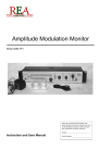
1
MAIB Control User Manual Application Note 1306 Revision: 1.3 October 2013 pei tel Communications GmbH A member of peiker group www.peitel.de Table of Contents 0 History.........................................................................................................................3 1 Introduction ................................................................................................................3 2 System Description .....................................................................................................3 2.1 System Requirements ................................................................................................... 4 2.2 Data Transfer between PC and MAIB ............................................................................. 4 2.3 Software Installation..................................................................................................... 5 2.3.1 MAIB Driver Installation .......................................................................................... 5 2.3.2 Microsoft® .NET Framework 2.0 Installation .............................................................. 8 2.3.3 MAIB Control Installation ........................................................................................ 8 3 Software Description...................................................................................................9 3.1 Initial Setup ................................................................................................................ 11 3.2 MAIB Configuration ..................................................................................................... 12 3.2.1 General Information .............................................................................................. 12 3.2.2 Configuration of the Radio Devices ......................................................................... 13 3.2.3 User Defined Configuration .................................................................................... 14 3.2.4 Setting up the Sensibility for Hands-Free Talking...................................................... 17 3.2.5 Active/Passive Volume Ratio ................................................................................... 18 3.2.6 Signal Tone On/Off................................................................................................ 18 3.2.7 MAIB Rundown Time ............................................................................................. 19 3.2.8 Key Priority ........................................................................................................... 19 3.2.9 LED Configuration ................................................................................................. 20 3.2.10 Forwarding of Hook Information ........................................................................... 21 3.2.11 Volume Level of External Loudspeakers ................................................................. 21 3.2.12 Accessory Volume................................................................................................ 22 3.3 Loading Settings from the MAIB ................................................................................... 22 3.4 Reset to Factory Defaults ............................................................................................. 23 3.5 Export and Import Settings .......................................................................................... 23 Application Note 1306 Page 2 MAIB Control User Manual 1.3 0 History Date Revision Author Comments 27.08.2012 04.06.2013 1.0 1.1 RN ME First Release Revision 28.06.2013 07.10.2013 1.2 1.3 RR CS Revision Revision/Translation Table 1: History 1 Introduction This document describes the program MAIB Control. The purpose of MAIB Control is to configure a MAIB (Migration Audio Interface Box). 2 System Description Settings that can be configured with MAIB Control are listed below: Adjustment of the volume level for all three radio devices Adjustment of the volume level for the hands-free microphone, as well as audio and control accessories Setting of parameters for the PTT buttons of the audio and control accessories Configuration of the power management Configuration of acoustic and optic signals Notice: Pre-defined configurations are available for several types of radio devices. Application Note 1306 Page 3 MAIB Control User Manual 1.3 2.1 System Requirements Minimal requirements: At least 25 MB free hard disk space Operating systems Microsoft® Windows® XP, Windows® Vista, Windows® 7 (64 bit versions are supported as well) A USB port Microsoft® .NET Framework 2.0 It is recommended to be connected to the internet during the installation of the MAIB drivers. Administrator permissions on your PC are necessary for the installation. 2.2 Data Transfer between PC and MAIB Data are transferred between PC and MAIB using a USB interface. The required USB cable is available as an optional accessory. This specific cable adds an RS232-interface to the PC (COMconnection). Application Note 1306 Page 4 MAIB Control User Manual 1.3 2.3 Software Installation 2.3.1 MAIB Driver Installation In Windows® XP, Windows® Vista and Windows® 7, just plug the USB cable into a free USB port on your PC. The Windows® operating system will download the drivers from the internet and install all necessary files automatically. If Windows® asks to install the drivers manually or if no internet connection is available, the drivers can be downloaded from: http://www.ftdichip.com/Drivers/VCP.htm After the installation, the COM port can be located in the device manager. It is listed as USB Serial Port (COMx)1. Please follow the instructions below, to configure the port in the device manager: Vista and Windows®7: Either use the search function of the START menu to find the Device Manager: Figure 1: Search function Windows® Vista and 7 1 "COMx" stands for the COM port number, which is automatically assigned by the PC; e.g. COM1, COM2, COM3, etc. Application Note 1306 Page 5 MAIB Control User Manual 1.3 Or open the Control Panel and select the Device Manager: Figure 2: Windows® 7 Control Panel In Windows® XP: The Device Manager is located in the Control Panel. Open the Control Panel, select the System icon > Hardware tab > Device Manager button. Figure 3: The COM port in the Device Manger window of Windows® 7 Application Note 1306 Page 6 MAIB Control User Manual 1.3 The new USB Serial Port (COMx) appears in the Ports (COM & LPT) section. Please note the COM port number (COMx) for later use during the MAIB Control set-up. It is recommended to reduce the Latency Timer of the COM port: Double-click USB Serial Port (COMx) > select the Port Settings tab > press the Advanced… button. Figure 4: "Port Settings" tab In the Advanced Settings for COMx window, change the Latency Timer to 1 msec. Figure 5: Advanced settings for the COMx port Application Note 1306 Page 7 MAIB Control User Manual 1.3 2.3.2 Microsoft® .NET Framework 2.0 Installation Framework version 2.0 is needed to run MAIB Control. MAIB Control will generate an error message at start-up, if this Framework version is not available. If necessary, Framework version 2.0 is available for download from: http://www.microsoft.com 2.3.3 MAIB Control Installation After the installation of the software packages (see also 2.3.1 MAIB Driver Installation and 2.3.2 Microsoft® .NET Framework 2.0 Installation), the installation of MAIB Control can begin. Execute the setup file and select the language for the installation dialog. Figure 6: Set-up language selection Go through the installation process by confirming the dialog windows on the screen. Figure 7: Welcome window of the setup assistant Application Note 1306 Page 8 MAIB Control User Manual 1.3 3 Software Description Figure 8: MAIB Control overview Application Note 1306 Page 9 MAIB Control User Manual 1.3 General information, like for example the software version, can be accessed in this way: Figure 9: Help menu Go to menu ? > Info about MAIB Control. Figure 10: About window Application Note 1306 Page 10 MAIB Control User Manual 1.3 3.1 Initial Setup If not already done during the installation process, select the program's language now. Go to menu Settings > Language, chose the language and confirm your selection. Next, configure the communication settings. Go to menu Settings > Serial Interface. The Communications Settings window opens. Figure 11: Communication settings Chose the correct COM port (see also 2.3.1 MAIB Driver Installation). Now the program is ready to configure the MAIB. This setting only needs to done once. To test the connection between MAIB and PC, select the button Read settings in the bottom left corner of the window (see also 3.3 Loading Settings from the MAIB). After the connection is established successfully, all settings stored in the MAIB are downloaded to the program and the status display shows: Figure 12: Status display after the MAIB's settings were downloaded to MAIB Control Application Note 1306 Page 11 MAIB Control User Manual 1.3 If the connection fails, the status display shows: Figure 13: Status display at failed connection Trouble-Shooting: If the connection fails … Check first, if the power supply of the MAIB is connected. Then check, if the 3.5 mm jack of the MAIB Programming Cable (USB) is plugged into the correct connector of the MAIB. Also make sure, that the correct COM port was selected in MAIB Control. 3.2 MAIB Configuration 3.2.1 General Information Once the connection between MAIB and PC was established, MAIB Control displays the following information in the Information section: Status Software version including release date Hardware revision of the MAIB Serial number Figure 14: Status display after setting connection settings The status display field confirms actions in green and gives error messages in red. Application Note 1306 Page 12 MAIB Control User Manual 1.3 3.2.2 Configuration of the Radio Devices Radio device types can be selected on the General tab > Connection configuration > Device connector 1 to 3. For every radio device type, volume levels are pre-defined, which are accepted by this selection. Before changing any settings, make sure, that the output volume levels at the radio devices themselves are set to full volume and are not getting changed afterwards. The option user defined radio device allows selecting volume levels separately. Please find instructions below. This procedure is required, if a radio device type is not listed in MAIB Control or if the pre-defined settings don't meet acoustic expectations. This might be the case if radio devices are programmed differently than standard. Figure 15: Drop-down-menu with various radio devices Application Note 1306 Page 13 MAIB Control User Manual 1.3 3.2.3 User Defined Configuration If a user defined radio device was selected in one of the drop down menus Device connector 1-3, it can be configured in more detail on the respective User defined device 1-3 tab. Figure 16: Tabs for user defined device settings Notice: For all pre-defined radio devices, the settings are stored on the MAIB and can't be customized by the user. The output amplification Audio out, the input sensitivity Audio in and the sidetone time must be configured. Output amplification stands for the AF level (Audio Frequency level), which is transmitted from the MAIB to the radio device. Input sensitivity stands for the AF level, which is transmitted from the radio device to the MAIB. Sidetone time stands for the period of time after transmission, during which the radio device transfers the incoming AF level directly to the output device. To avoid acoustic feedback with the hands-free microphone, the output amplification is set to mute for a period of time, which is defined as sidetone time. Notice: For the adjustment procedure, a working radio link is needed. Application Note 1306 Page 14 MAIB Control User Manual 1.3 Adjustment of the output amplification: Press the PTT button on the connected control accessory and start talking in a loud voice, holding the accessory in normal speaking distance. Judge the voice output quality on the other end of the radio link. The output volume should be increased slowly. Starting with 0 and increase the value until on the other end of the radio link, a clearly comprehensible voice without overmodulation arrives. Figure 17: Audio out, Audio in and Sidetone time For your orientation, some approximate values for the output volume: 0 equals about 5 mVrms 100 equals about 100 mVrms 255 equals about 1 Vrms (for R∞) Adjustment of the input sensitivity: Set the radio device to a volume level higher than zero and don't change it anymore. Some radio devices have a much higher harmonic distortion when set to full volume. Therefore we recommend setting the volume level to half of the maximum. Talk with normal voice on the other side of the radio link. Now adjust Audio in starting with 0 until the volume level displayed exceeds 0 dB. Peak volume levels should not exceed 12 dB. Application Note 1306 Page 15 MAIB Control User Manual 1.3 Figure 18: Volume level display (green-yellow bar) For your orientation, approximate values for the input sensitivity: 5 Vrms equals about 50 1 Vrms equals about 180 100 mVrms equals about 255 Please note the following draw-back: The AF level that goes into the radio device interface 1 of the MAIB, is only displayed on the User defined device 1-tab. Same applies to the radio device interfaces 2 and 3 and tabs User defined device 2 and 3. Setting of the sidetone time (in seconds): This setting is only necessary for radio devices, which create a sidetone, in transferring the input signal to the output device after the PTT button is released. This could lead to acoustic feedback with the hands-free microphone. During the sidetone time, the radio device interface is set to mute. In normal cases, this setting can remain at 0 seconds. The sidetone time can be adjusted from 0 s..60 s. Confirm the configuration by pressing the ENTER key. Application Note 1306 Page 16 MAIB Control User Manual 1.3 3.2.4 Setting up the Sensibility for Hands-Free Talking The settings for the hands-free microphone Volume hands-free are on the left side of the General tab in MAIB Control. Notice: For the adjustment procedure, the hands-free microphone must be built-in. The user must talk in a normal speaking position or distance. For the configuration, use the slider Volume hands-free microphone. The range is displayed in percent, 100 is equivalent to full volume. The volume level is measured below the volume level slider. Start from the lowest position and move the slider to a higher percentage until the volume level display reaches over 0 dB. The peaks of the volume level should not reach higher than the 20 dB mark. Figure 19: Volume level of the hands-free microphone Trouble-Shooting: If the volume level isn't displayed during talking, check, if the hands-free microphone is installed correctly and plugged in. Make sure that Show volume level is checked in MAIB Control. Application Note 1306 Page 17 MAIB Control User Manual 1.3 3.2.5 Active/Passive Volume Ratio When a PTT button is pushed, the selected radio device (active) comes on with full volume level and the other radio devices (passive) are audible with reduced volume level. For radio devices in duplex operation, the ongoing conversation is better comprehensible, while the other radio devices can be listened in as well. At the moment, radio devices with duplex operation are not supported yet. For updates, please contact the manufacturer or visit: http://www.peitel.de The Active/Passive volume ratio slider adjusts the passive volume level of the loudspeaker of the audio and control accessory as well as of the external loudspeaker. Figure 20: Active/Passive volume ratio slider 3.2.6 Signal Tone On/Off The check box Attention signal tone enables and disables signal tones. Events generating attention signal tones are: Reduction or increase of the total audio volume using external volume buttons. Switching-on the MAIB by using accessories, like for example the handset HA26. Figure 21: Attention signal tone check box Application Note 1306 Page 18 MAIB Control User Manual 1.3 3.2.7 MAIB Rundown Time The MAIB rundown time defines how long the MAIB stays active after the ignition is switched off. Within this period of time sending and receiving radio messages is still possible. After this time, the MAIB goes into power save mode and can only activated again by starting the ignition. Notice: This feature also depends on the configuration of the radio devices in use. Figure 22: Pull down menu "MAIB rundown time" 3.2.8 Key Priority The Key priority setting determines which PTT buttons (keys) connected to the MAIB have higher priority, external PTT buttons (for example a TF5) or the PTT buttons of a control accessory (for example a handset HA26). Figure 23: Pull down menu key priority The settings with PTT-key priority have in common: The device with higher priority is able to take the connection over from the other device. Application Note 1306 Page 19 MAIB Control User Manual 1.3 3.2.9 LED Configuration The MAIB has three connectors for LEDs, to make incoming radio messages visible (constant illumination) and to show, which radio device is engaged by a subscriber (flashing). The LED function is activated by checking LED On/Off. Figure 24: Settings for LEDs and LSB Additionally, there's a possibility to use a Loudspeaker Splitter Box (LSB, optional accessory of the MAIB). The LSB distributes the audio level on three loudspeakers, one for each connected radio device. Incoming radio messages are allocated to the respective radio device by spatial hearing. This functionality only works, if the use of the LEDs is disabled. The LSB option is selected by checking off the box LSB Control (see also Figure 24: Settings for LEDs and LSB). The LED rundown time is set by increments of 1 s. It determines, how long after a radio message came in, the respective LED is still illuminated. If the MAIB is set to LSB control, the LED rundown time determines, how long after a radio message came in, the signal of the external loudspeaker can still be allocated to a specific loudspeaker. Application Note 1306 Page 20 MAIB Control User Manual 1.3 3.2.10 Forwarding of Hook Information If an accessory with hook switch mechanism is connected to the MAIB (for example handset HA26), select radio devices, where hook information should be forwarded to, by checking the boxes. Figure 25: Selection of radio devices for hook forwarding 3.2.11 Volume Level of External Loudspeakers Use the slider to select the overall volume of the external loudspeaker in increments of 6 dB. Figure 26: Setting the overall volume of the external loudspeaker It is also possible to connect two external volume buttons to the MAIB (volume up and volume down). They are used to change the volume during normal operation. The volume adjustment of the accessories is also done with this buttons. For this reason, the use of the buttons is restricted to specific situations. The volume of external loudspeakers is only adjustable if either: A ME110 hand microphone is connected HA26 handset is connected and positioned in the cradle No accessory is connected Application Note 1306 Page 21 MAIB Control User Manual 1.3 3.2.12 Accessory Volume Use the slider to select the overall volume of the control accessory in increments of 6 dB. Figure 27: Setting the overall volume of the control accessory During normal operation, this volume can also be adjusted using two external buttons (volume up and volume down) connected to the MAIB if: A HA26 handset is connected and picked up from the cradle 3.3 Loading Settings from the MAIB Find the button Read settings in the left bottom corner of the window. If pressed, all parameters on the connected MAIB are collected and displayed on screen. When a MAIB is connected at start-up of the program, this happens automatically. Figure 28: Load settings from the MAIB Notice: The read-out of the MAIB settings can take up to 10 seconds. Application Note 1306 Page 22 MAIB Control User Manual 1.3 3.4 Reset to Factory Defaults Pressing the button Set to default settings will reset the MAIB to factory default settings. Notice: All settings done before will be lost. Figure 29: Reset to factrory defaults 3.5 Export and Import Settings The current configuration of the MAIB can be stored into a file on the computer and if required loaded onto another MAIB. This feature allows creating several profiles with different MAIB configurations, which can be quickly accessed when needed. To export settings, go to menu File > Export Settings and select a folder and type in a file name. To load settings onto the MAIB, go to menu File > Import Settings and select the required file. Figure 30: Export and import settings END OF DOCUMENT Application Note 1306 Page 23 MAIB Control User Manual 1.3