1
Support: 800-875-7243
How to Use This Manual
Acrobat provides various methods for navigating through a PDF document. The
recommended method of navigating this manual is through the use of the Bookmarks.
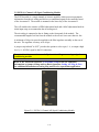
To browse using Bookmarks:
Show the Bookmarks list.
By default the manual will open with the Bookmarks list open on the left side of the
document. If you do not see the bookmarks list choose Window > Show Bookmarks to
open the list or click the Bookmarks tab to bring the list to the front of its group.
To expand the bookmark list
Bookmarks can be subordinate to other bookmarks in the list. If a bookmark has
subordinate bookmarks under it then it will have a plus sign next to it. To expand the book
mark list click the plus sign. After the list is expanded a minus sign will be displayed next
to the bookmark. To collapse the list click on the minus sign.
To jump to a topic using its bookmark
Click the bookmark’s text in the list and the document will jump to the corresponding page
in the manual.
Additional Navigation Methods:
• To go to the next page, click the Next Page button in the navigation toolbar or status
bar, press the Right Arrow key, press Ctrl (Windows) or Option (Mac OS) and the Down
Arrow key, or choose Document > Next Page.
• To go to the previous page, click the Previous Page button in the navigation toolbar
or status bar, press the Left Arrow key, press Ctrl (Windows) or Option (Mac OS) and the
Up Arrow key, or choose Document > Previous Page.
• To move down one line, press the Down Arrow key.
• To move up one line, press the Up Arrow key.
• To move down one screenful, press Page Down or Return.
• To move up one screenful, press Page Up or Shift+Return.
• To go to the first page, click the First Page button in the navigation toolbar or status
bar, press the Home key, or choose Document > First Page.
• To go to the last page, click the Last Page button in the navigation toolbar or the
status bar, press the End key, or choose Document > Last Page.
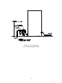
A
ccu-Setter II User’s Manual
GAGES
Edmunds
Table of Contents
Preface
Manual Revision History
Trademark Information
i
i
Introduction
Summary & Features
Document Conventions
Anti-Static Precautions
Glossary of Terms
Quick Start Guide
Programming Reference Guide
1-1
1-2
1-2
1-3
1-6
1-7
System Description
Number References
Specifications
Spare Parts
Overall Unit
Front Panel
Rear Panel
Rear Panel Pin Assignments
Input/Output Pin Assignments
RS-232C
E9310, (2) Channel LVDT Signal Conditioning Module
E9320, (4) Channel LVDT Signal Conditioning Module
E9330, (1) Channel A/E Signal Conditioning Module
E9340, (2) Channel A/E Signal Conditioning Module
Filter Regulator Assembly
2-1
2-2
2-2
2-3
2-4
2-6
2-8
2-8
2-10
2-11
2-12
2-13
2-14
2-15
Basic Operation
Setup & Operation Summary
Unpacking & Setting Up
Single Unit Setup
Multiple Unit Setup
Signal Conditioning Module Setup
Signal Conditioning Module Auto Recognition
Programming
Programming Guide
Gaging Formulas
Single Check Programming
Multiple Check Programming
Multiple Fixture Programming
System Programming
Inputs Setup
Setting A/E Mag & Zero
Setting LVDTs
3-1
3-2
3-2
3-5
3-6
3-6
3-7
3-9
3-10
3-15
3-22
3-31
3-39
3-45
3-45
3-47
Calibration
Single Check
Multiple Check
Multiple Fixture
3-48
3-48
3-50
3-52
Gage Operation
Single Check Measurement
Multiple Check or Multiple Fixture Measurement
Offloading Gage Results
3-54
3-54
3-56
3-58
Advanced Operation
A/E Module Setup
Output Jumpers
Module Installation
A/E Maintenance
LVDT Module Setup
Jumper Settings
Inputs/Outputs
Attenuation
Module Installation
Obsolete Signal Conditioning Modules
External Device Communication
RS232
Input/Output Board
Description
Typical I/O connections
Auto Air Shutoff (Optional)
Troubleshooting
4-1
4-2
4-3
4-4
4-6
4-7
4-7
4-9
4-10
4-11
4-12
4-12
4-22
4-22
4-23
4-25
4-28
Index
5-1
Warranty Information
Service & Support Information
6-1
6-1
Table of Figures
Figure 1.1 - Programming Reference Guide
1-7
Figure 2.1 - Overall Basic unit
Figure 2.2 - Front Panel
Figure 2.3 - Rear Panel
Figure 2.4 - I/O Pins
Figure 2.5 - I/O Connections
Figure 2.6 - RS232C Pins
Figure 2.7 - E9310, (2) Ch. LVDT Module
Figure 2.8 - E9320, (4) Ch. LVDT Module
Figure 2.9 - E9330, (1) Ch. A/E Module
Figure 2.10 - E9340, (2) Ch. A/E Module
Figure 2.11 - Supply Air Filter/Regulator
2-3
2-5
2-7
2-8
2-9
2-10
2-11
2-12
2-13
2-14
2-15
Figure 3.1 - Base Feet
Figure 3.2 - Filter Regulator Mounting
Figure 3.3 - Air Connections
3-3
3-3
3-4
Figure 4.1 - A/E Modules, E9330 & E9340
Figure 4.2 - Output Pin Jumpers
Figure 4.3 - A/E Block
Figure 4.4 - LVDT Modules, E9310 & E9320
Figure 4.5 - I/O Jumpers
Figure 4.6 - Attenuation Jumpers
Figure 4.7 - RS232C Pins
Figure 4.8 - Typical I/O Connections
4-1
4-2
4-5
4-6
4-8
4-9
4-12
4-23
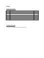
Preface
Manual Revision History
Revision Change
0
Original Issue
Date
6/3/04
Trademark Information
“Accusetter” is a registered trademark of Edmunds Gages
i
Introduction
1.0 Summary and Features
The Edmunds Gages Accusetter II offers many sophisticated features and benefits for
durable and robust shop floor operation.
The Accusetter II is a microprocessor based gaging column that combines a 101 discrete
tri-color LED bargraph display for easy visual monitoring of dimensional measurement
characteristics, with an eight digit alpha numeric display for precise size readings and
operator prompting messages. Illuminated range indicators identify which of the eight
inch or eight millimeter ranges have been selected. The tri-color LED bargraph conveys
both measurement size and status. A single rotary entry switch and six dedicated
pushbuttons provide all of the operator control functions.
The unit is housed in a heavy duty reinforced aluminum case with a module bay for
interchangeable plug in modules which will accommodate Edmunds LVDT type gaging
probes or Edmunds and nearly all major brands of air tooling. The rear panel of the
column contains two female DB25 connectors which provide 6 channels for input/output
bussing of analog signals. These connectors also provide various control/status signals
for the I/O accessory board. An RS-232C connector allows output of gage results to a
data collector. The Accusetter II will operate at any supply line voltage between 100
VAC to 240 VAC at either 50 or 60 HZ. An additional receptacle is provided for power
jumper cord connections for multiple column applications. The serial number with
revision letter is identified at the top of the rear panel of the Accusetter II.
The Accusetter II’s powerful microprocessor allows the user tremendous flexibility in
tailoring the column to match the gaging requirement. Each dimension can be
functionally displayed as a deviation from nominal, absolute size, +peak, -peak, TIR or
class functions. The automatic mastering provides precise calibration without the usual
need of precisely adjusting trim pots and knobs. The user is provided with three distinct
application gaging programs to choose from. The single check program simplifies the
operation of the Accusetter II to allow only a single check measurement. The multiple
check program is Accusetter II’s unique “4 in 1” feature that allows the user to configure
up to four dimensional checks to be gaged simultaneously in one column. In the multiple
fixture program, an enhanced single check measurement is available for up to four
separate gages. Whenever power is first turned on to the Accusetter II, the display will
scroll the software version and the present application program and the module ID.
1-1
1.1 Document Conventions
RUN = Shortcut Programming Key
“INCH” = Alphanumeric Display
1.2 Anti-Static Precautions
When working inside the Accusetter II cabinet or handling signal conditioning modules
use caution to protect against damage from static electricity. Use of an anti-static wrist
band or other grounding procedures are recommended.
Power to the column must be turned off prior to installing or removing a signal
conditioning module.
1-2
1.3 Glossary of Terms
Absolute displays the check size as the actual part size.
An A/E (Air to Electric) transducer converts changes in pneumatic pressure into an
electrical signal.
+APPROACH (or -APPROACH) are optional user defined programmable values
approaching the max and min part limits.
AVG (Average) is a function that returns the average check reading.
Bypass is a function that displays a live input reading
A part Check is an input or combination of inputs expressed with a gaging mode to
exhibit a part characteristic.
Calibration is a procedure used to automatically set the magnification and zero shift for
a check by comparing actual gage readings to known certified sizes of a master or
masters.
Deviation displays how much a check size deviates from the nominal size as a variation.
A gaging Formula allows the user to add, subtract, multiply, or divide inputs from
transducers A, B, C, and D.
A Function defines how an input or check will be displayed on the readout. Function
options are Bypass, Average, +Peak, -Peak, TIR, and TOL Check.
The Gain setting on the A/E signal conditioning module sets the amplification factor of
an input signal to a usable value that can be interpreted by the readout device
A Gage is a mechanical device used to measure part characteristics.
Gage Readings are the input values obtained during the gage cycle.
A High Level Signal is an amplified +/-2.5VDC signal that reflects the number of bars
illuminated on the bargraph display.
An Input is the assigned name given to a signal that is to be utilized in a gaging formula.
In LIVE RDG (Live Reading) mode the input signal is directly displayed on the
alphanumeric and bargraph displays in real time.
A Low Level Signal is the raw unamplified voltage from an LVDT or A/E transducer.
1-3
An LVDT (Linear Variable Differential Transformer) is an electromechanical
transducer that converts the linear motion of its contact tip to an AC voltage which can be
interpreted by a readout device.
Magnification is the enlargement of an input signal to a usable value that can be
interpreted by the readout device.
A Maximum (MAX) Master is a precision replica of the gaged part manufactured to the
upper specification limit of the part features, inspected and certified to size, for use in the
calibration of the gage.
A Minimum (MIN) Master is a precision replica of the gaged part manufactured to the
lower specification limit of the part features, inspected and certified to size, for use in the
calibration of the gage.
A Multiple Check Program allows the user to program up to four dimensional checks to
be gaged simultaneously in one column. All checks must use the same range.
A Multiple Fixture Program allows the user to program the Accusetter II with up to
four separate gages each consisting of a single check. The gages can use different ranges.
A Multiplier is part of the check formula. The input reading is multiplied by the this
factor. It is determined by the number of probes used to perform the measurement or to
correct any ratio that may be introduced by any contact arms or tooling.
Polarity is the signed value (+ or -) applied to the magnification of an input to determine
the direction of the input value change.
In +PEAK (or -PEAK) modes the largest (or smallest) size reading since the last reset is
displayed.
Range is the full scale value of the bargraph display.
An R & R is a statistical study performed on a gage to determine the gages repeatability
and reproducibility.
Repeatability is the measurement variation of a gage when used by one operator or
under one set of environmental conditions.
Reproducibility is the variation in measurement averages of a gage when used by more
than one operator or under varying environmental conditions.
The Resolution of a gage is the smallest significant digit of the measurement data that is
displayed.
In Run Mode the user can perform the actual part measurements.
1-4
A Signal Conditioner is a circuit board that modulates and amplifies the LVDT or A/E
signal used by the readout device.
A Single Check Program allows the user to program the Accusetter II for one
dimensional check.
In Setup Mode the user can program the required variables for the par checks and
transducers.
In TIR (Total Indicator Reading) mode the difference between the largest and smallest
readings measured is displayed.
TOL Check is a check function that displays the average reading measured when the
check is within the programmed tolerance limits and displays the +Peak or -Peak
readings when the check result is outside the programmed tolerance limits.
A Zero (or Mean) Master is a precision replica of the gaged part manufactured to the
nominal dimensions of the part features and calibrated to size for use in the calibration of
the gage.
A Zero adjustment knob allows operator to drive the displayed readout value to a
desired setting within a limited range.
1-5
1.4 Quick Start Guide
The following steps must be taken to prepare the Accusetter II for operation.
1) Unpack and setup the unit.
• Rotate the front foot 90° from its shipping position.
• For air gaging applications, rotate the rear foot 180° from its shipping position and
install the filter regulator assembly. Connect 60 psi min supply air to the filter
regulator assembly
Note: See "Basic Operations, Unpacking & Setup " for additional information, page 3-1
2) Setup and install the signal conditioning module if it was not installed before
shipment and connect the gage tooling.
Power to the column must be turned off prior to installing or removing a signal
conditioning module.
• Check that the jumpers and switches on the LVDT or A/E signal conditioning board
to be used are properly setup for the application to be run.
• Install the signal conditioning module into the lower bay and secure with the two
thumb screws on the front panel.
• Plug in the LVDT(s) or airline from the gaging fixture to the signal conditioning
module.
Note: See the "Advanced Operation, Module Setup" section for additional information,
page 4-1.
3) Program Accusetter II for the application.
• Plug the power cord into the rear of the unit and to a 100 VAC to 240 VAC 50/60 Hz
power supply. Turn the unit on using the on/off switch on the rear of the unit.
• Using the programming keys and the enter button program the variables such as
range, scale, and limits for the application.
Note: See the "Basic Operation, Programming" for additional information, page 3-7
4) Set up magnification and zero for the air inputs.
• Using the masters for the gage tooling and the mag and zero adjustments on the signal
conditioning module setup the air input(s).
Note: See "Basic Operation, Input Setup " for additional information, page 3-40
5) Master the gage using Calibration mode.
Note: See "Basic Operation, Calibration" for additional information, page 3-43
6) Select Run mode and the unit is ready for gaging.
1-6
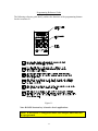
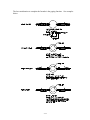
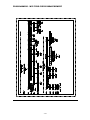
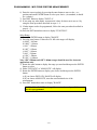
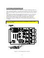
Programming Reference Guide
The following reference guide briefly outlines the functions of the programming buttons
for the Accusetter II.
Figure 1.1
Note: RANGE shortcut key is inactive for air applications.
NOTE: If the RANGE is changed the master sizes and part limits must also
be reprogrammed.
1-7
System Description
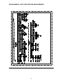
2.0 Number References
Component
Basic Accusetter II Unit
(2) Channel LVDT Signal Conditioning Module
(4) Channel LVDT Signal Conditioning Module
(1) Channel A/E Signal Conditioning Module
(2) Channel A/E Signal Conditioning Module
Power Cable
Air Filter/Regulator Assembly
Interface Cable
Printer Cable
Power Jumper Cable
I/O Accessory Board
Send Data Foot Switch*
TIR Reset Foot Switch*
Auto Air Shutoff Kit (Optional)
Includes: Valve Assembly
Shutoff Cable*
Edmunds Gages Number
E9300
E9310
E9320
E9330
E9340
4550111
5801302
4550200
5809060
4550120
5911013
5911100
5911101
5913250
5911200
5911018
*Note: Foot switch and air shutoff cables must be plugged into the "In/Out B" port.
A new Accusetter II will be supplied with an E9310, E9320, E9330, or E9340 signal
conditioning module, however the Accusetter II is compatible with the obsolete
signal conditioning modules listed below:
Obsolete Signal Conditioning Modules
(2) Channel LVDT Signal Conditioning Module
(4) Channel LVDT Signal Conditioning Module
(1) Channel A/E Signal Conditioning Module
(1) Channel A/E Signal Conditioning Module
(2) Channel A/E Signal Conditioning Module
(2) Channel A/E Signal Conditioning Module
Edmunds Gages Number
E9010
E9020
E9030
E9031
E9040
E9041
Power to the column must be turned off prior to installing or removing a signal
conditioning module.
2-1
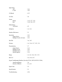
2.1 Specifications
Overall Dimensions
Power Requirements
Power Consumption
Air Requirements (E9330 or E9340 Module Only)
Pressure
Flow Rate
Environmental Operating Conditions
Max Temperature
21.25” x 2.50” x 9.00”
100 VAC to 240 VAC 50/60 Hz
12 Watts @ 120 VAC, 100 mA
60 psi
1.6 scfm/air tooling nozzle
50°C/120°F
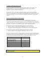
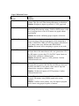
2.2 Recommended Spare Parts
Below is a list of recommended spare parts for the Accusetter II. These items may be
ordered separately from Edmunds Gages, they are not included with the basic unit.
Part
Edmunds Gages P/N
Qty.
Basic Unit
10 Amp Fuse
4190135
2
Limit Pointer Assembly
5809508-BM
2
E9310 & E9320 LVDT Modules
2 Position Shunt, .100 Spacing
4570117
1
E9330, (1) Ch. A/E Module
A/E Block
Needle Valve Assembly
O-Ring, Restriction Screw
O-Ring, Body
Bias Restrictor Assembly
Filter Disc
Bias Restrictor O-Ring
Transducer O-Ring
Air Filter Replacement Element
2 Position Shunt, .100 Spacing
3101500
3101045
5900026
5900027
3101188-B
3101130-B
5900026
5900043
SMC #KT-AF2000-5B
4570117
1
1
1
1
1
2
2
2
1
1
E9340, (2) Ch. A/E Module
A/E Block
Needle Valve Assembly
O-Ring, Restriction Screw
O-Ring, Body
Bias Restrictor Assembly
Filter Disc
Bias Restrictor O-Ring
Transducer O-Ring
Air Filter Replacement Element
2 Position Shunt, .100 Spacing
3101510
3101045
5900026
5900027
3101188-B
3101130-B
5900026
5900043
SMC #KT-AF2000-5B
4570117
1
2
2
2
1
2
2
4
1
1
2-2
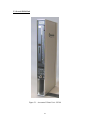
2.3 Overall E9300Unit
Figure 2.1 - Accusetter II Basic Unit - E9300
2-3
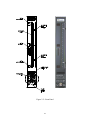
2.4 Front Panel
The Accusetter II front panel consists of the following items:
Bargraph display - The 10 inch, 101 point, three color LED bargraph display is the
primary readout for the Accusetter II. When over and under limits are programmed, the
bargraph will change colors to visually indicate over or under (red), approaching part
limits (yellow), or good parts (green).
Range Annunciators - Located next to the bargraph, the half scale indicators display the
bargraph values for the various ranges.
Adjustable Limit Pointers - Mechanically positioned limit indicators.
Range Indicator - Displays the currently selected full scale range. Inch ranges are
displayed in green. Metric ranges are displayed in amber.
Range Options:
Inch
.0002"
.0005"
.001"
.002"
.005"
.010"
.020"
.050"
Metric
.005mm
.01mm
.02mm
.05mm
.10mm
.20mm
.50mm
1.00mm
Alphanumeric Display - During gaging operation the alphanumeric display provides a
digital readout of the bargraph value. During programming the alphanumeric display
shows information on the current programming selections.
Programming Keys - Provide a shortcut to the various programmable options.
Rotary Enter Button - The enter button can be either pressed or rotated and is used
during the programming of the Accusetter II.
2-4
Figure 2.2 - Front Panel
2-5
2.5 Rear Panel
The Accusetter II rear panel contains the following items:
Serial Number - The Edmunds Gages serial number is listed at the top of the rear panel.
Fuse Locator - Contains a 10 Amp fuse.
Power Switch - Use to switch the unit on or off.
Power Connector - Plug the power cable (Edmunds #4550111) into the power connector
and connect to input line voltage from 100 to 240 VAC at 50 or 60 Hz. The Accusetter
II contains a universal power supply that will automatically adjust to any line voltage in
the above range.
Power Outlet Jumper - In a multiple Accusetter II setup, plug power jumper cables
(Edmunds #4550120) from the power outlet jumper on one unit to the power connector
on the next unit.
RS-232C Connector - Use to output gage results to an external data collector.
IN/OUT A (25 Pin) - Use to input/output parallel and analog signals from another
Accusetter II or to an external device using interface cable, Edmunds #4550203. See
figure 2-3 for pin assignments.
IN/OUT B (25 Pin) - Use to input/output parallel and analog signals from another
Accusetter II or to an external device using interface cable, Edmunds #4550203. See
figure 2-3 for pin assignments.
44 PSI Inlet - When the air to electric module is installed in the lower bay, an air hose
fitting will extend out the 44 psi inlet port on the rear of the Accusetter II. An air line is
connected to this fitting and to the outlet side of the air filter/regulator assembly.
2-6
Figure 2.3 - Rear Panel
2-7
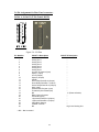
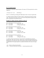
2.6 Pin Assignments for Rear Panel connectors
In/Out A, In/Out B (25 Pin Female DSUB)
Figure 2.4 - I/O Pins
Pin Number
1
2
3
4
5
6
7
8
9
10
11
12
13
14
15
16
17
18
19
20
21
22
23
24
25
IN/OUT A Description
IN/OUT B Description
Analog Out 1
Analog Out 2
Analog Out 3
Analog Out 4
Analog Out 5
Analog Out 6
Air shut off present (Input)
Spare 1 (Input)
Air off (Output)
Spare 2 (Output)
AGND
Over Relay/Class Bit 0 (Output)
Good Relay/Class Bit 1 (Output)
Under Relay/Class Bit 2 (Output)
Hold (Input)
Status/Class Request (Input)
Footswitch (Send Data/Input)
NC
Relay Output Common
TIR Reset (Input)
+Approach/Class Bit 3 (Output)
-Approach/Class Bit 4 (Output)
Class Bit 5 (Output)
Isolated Common
NC
• NC = Not connected
2-8
“
“
“
“
“
“
“
“
“
“
“
“
“
“
“
“
“
+V (External Switch)
“
“
“
“
“
“
High Level Analog Out
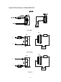
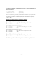
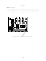
Typical IO Connections - I/O Board #5911013
OUTPUT "SINKING"
IO A/B
IO A/B
+24 VDC (+)
P13
LOAD
P13
LOAD
P19
GOOD
RELAY
CURRENT
FLOW
P19
0 VDC (-)
24VDC
Power Supply
+
OUTPUT "SOURCING"
IO A/B
IO A/B
P13
LOAD
P19
+24 VDC (+)
P19
GOOD
RELAY
CURRENT
FLOW
0 VDC (-)
LOAD
P13
+
24VDC
Power Supply
Figure 2.5
2-9
-
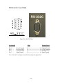
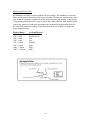
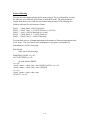
RS232C (9 Pin Female DSUB)
Figure 2.6 - RS-232C Pins
Accusetter II
Pin 1
Pin 2
Pin 3
Pin 5
=
=
=
=
Chassis Ground.
Receive (RXD)
Transmit (TXD)
Signal Ground
Cable
External Device
ß----------------------------à
ß----------------------------à
ß----------------------------à
ß----------------------------à
Chassis Ground.
(TXD) Transmit.
(RXD) Receive.
Signal Ground.
Note: Pin2 and 3 are jumper selectable based upon the application.
2-10
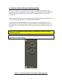
2.7 E9310 (2) Channel LVDT Signal Conditioning Module
The E9310 module is a two-channel signal conditioning amplifier for inductive type
transducers such as LVDTs that converts the outputs of the transducers into a conditioned
signal for the main controller board. The module is mounted in the lower bay of the
Accusetter II.
Input magnification must be set using jumpers allowing magnification reduction to be set
to 10x for long range transducers or 1x for standard transducers.
A jumper matrix on the board allows it to accept signals in or send signals out to the
analog output connector. By placing the jumper pin for the desired signal line on one of
the six buss lines, the signal can now be sent or received by any other units connected to
the buss.
Power to the column must be turned off prior to installing or removing a signal
conditioning module.
Refer to the Advanced Operation, LVDT Module Setup section for additional
information on jumper settings.
Figure 2.7 - E9310 (2) Channel LVDT Signal Conditioning Module
2-11
2.8 E9320 (4) Channel LVDT Signal Conditioning Module
The E9320 module is a four-channel signal conditioning amplifier for inductive type
transducers such as LVDTs that converts the outputs of the transducers into a conditioned
signal for the main controller board. The module is mounted in the lower bay of the
Accusetter II.
Input magnification must be set using jumpers allowing magnification reduction to be set
to 10x for long range transducers or 1x for standard transducers.
A jumper matrix on the board allows it to accept signals in or send signals out to the
analog output connector. By placing the jumper pin for the desired signal line on one of
the six buss lines, the signal can now be sent or received by any other units connected to
the buss.
Power to the column must be turned off prior to installing or removing a signal
conditioning module.
Refer to the Advanced Operation, LVDT Module Setup section for additional
information on jumper settings.
Figure 2.8 - E9320 (4) Channel LVDT Signal Conditioning Module
2-12
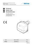
2.9 E9330 (1) Channel A/E Signal Conditioning Module
The E9330 module is a single channel air/electric amplifier which processes pneumatic
information from the air tooling and delivers a conditioned signal to the controller board
of the Accusetter II. The module is mounted in the lower bay of the Accusetter II.
The A/E module also contains a ZERO adjustment knob and a MAG adjustment knob for
initial input setup to accommodate the air tooling used..
The air tooling is connected to the air fitting on the front panel of the module. The
recommended length of air line from the module to the air tool is no more than six feet.
A minimum of 60 psi air must be supplied to the filter/regulator assembly on the rear of
the unit. The regulator is factory set to 44 psi.
A jumper strip labeled "A OUT" provides the option to select a pin, 1 -6, to output a high
level (+/-1.84VDC) signal to the I/O connectors.
Power to the column must be turned off prior to installing or removing a signal
conditioning module.
Refer to the Advanced Operation, A/E Module Setup section for additional
information on jumper settings and see Basic Operation, Setting A/E Mag & Zero
for additional information on setting Mag and Zero for a particular application.
Figure 2.9 - E9330 (1) Channel AE Signal Conditioning Module
2-13
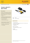
2.10 E9340 (2) Channel A/E Signal Conditioning Module
The E9340 module is a two channel air/electric amplifier which processes pneumatic
information from the air tooling and delivers a conditioned signal to the controller board
of the Accusetter II. The module is mounted in the lower bay of the Accusetter II
The A/E module also contains a ZERO adjustment knob and a MAG adjustment knob for
each input for initial input setup to accommodate the air tooling used..
The air tooling is connected to the air fitting on the front panel of the module. The
recommended length of air line from the module to the air tool is no more than six feet.
A minimum of 60 psi air must be supplied to the filter/regulator assembly on the rear of
the unit. The regulator is factory set to 44 psi.
A jumper strip labeled "A OUT" and "B OUT" provides the option to select a pin, 1 -6,
to output a high level (+/-1.84VDC) signal(s) to the I/O connectors.
Power to the column must be turned off prior to installing or removing a signal
conditioning module.
Refer to the Advanced Operation, A/E Module Setup section for additional
information on jumper settings and see Basic Operation, Setting A/E Mag & Zero
for additional information on setting Mag and Zero for a particular application.
Figure 2.10 - E9340 (2) Channel AE Signal Conditioning Module
2-14
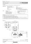
2.11 Supply Air Filter/Regulator Assembly
Any unit supplied with an A/E signal conditioning module will also be supplied with a
filter/regulator assembly. The assembly is mounted to the rear foot of the Accusetter II.
The regulator is factory preset to 44psi and requires a clean, dry air supply at 60psi min.
The regulator output is connected to a fitting on the A/E module that extends out of the
44psi inlet port on the rear panel of the Accusetter II.
Figure 2.11 - Supply Air Filter/Regulator
2-15
Basic Operation
3.0 Set up and Operation Summary
The following steps must be taken to prepare the Accusetter II for operation.
1) Unpack and setup the unit. See "Unpacking & Setup " below.
2) Setup signal conditioning module jumpers and install module. See the "Advanced
Operation" section.
Power to the column must be turned off prior to installing or removing a signal
conditioning module.
3) Program Accusetter II for the application. See the "Programming" section below.
4) Set up magnification and zero for the air gage input or inputs. See "Input Setup " below
or set up the LVDT probes. See "Input Setup " below.
5) Calibrate the gage(s). See "Calibration".
6) Select Run mode and unit is ready for gaging. See "Operation".
3-1
3.1 Unpacking & Setting Up
Unpacking
Ensure that the following items are received when the unit is unpacked:
• Basic Accusetter II unit (E9300)
• Signal Conditioning Module (E9310 or E9320 air module or E9330 or E9340 electronic
module)
• Power Cable #4550111
• Filter/Regulator (for air gaging modules E9310 or E9320 only) #5801302
• Hose Assembly (for air gaging modules E9310 or E9320 only) #3101053-B
Setup
The Accusetter II can be used as a stand alone unit or as part of a multiple Accusetter II
setup.
Single Accusetter II Setup
1) Turn the Accusetter II upside down and remove the front foot mounting screw.
2) Rotate the front foot 90° from its shipping position so that it is perpendicular to the
column and remount as shown below.
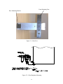
3) If air gaging is to be used, remove the two mounting screws for the rear mounting
bracket and rotate the rear foot 180° from its shipping position so that the air
filter/regulator assembly can be mounted as shown in figure 3.1.
4) Turn the unit right side up.
5) For air gaging applications only, attach the air line from the filter/regulator assembly to
the fitting extending from the rear of the column.
6) Ensure the power switch on the rear of the column is turned “OFF”.
7) Plug the power cord into the male electrical receptacle on the rear of the column.
8) Plug the power cord into a power source between 100VAC and 240VAC at 50 or 60
Hz.
9) For air gaging applications only, connect a source of clean, dry air at 60 psi min to the
air filter/regulator inlet. NOTE: The Accusetter II regulator is factory set to 44psi.
10) Connect the gage tooling to be used to the signal conditioning module. For air gaging
connect the air hose from the air plug, air ring, or air snap to the tooling port on the
front of the A/E module. For electronic gaging connect the one or two LVDTs to
inputs A and/or B on the front of the LVDT module.
11) Turn on the Accusetter II by turning the power switch on the rear of the unit to “ON”.
3-2
Front Mounting Foot
Rear Mounting Bracket
Figure 3.1 - Base Feet
Figure 3.2 - Filter/Regulator Mounting
3-3
Figure 3.3 - Air Connections
For Air Gaging Application Only
3-4
Multiple Accusetter II Setup
1) Turn the Accusetter II units upside down and remove the front foot mounting screws.
2) Rotate the front foot 90° from its shipping position so that it is perpendicular to the
column and remount as shown above. Up to three columns can be mounted on the
same front foot.
3) If air gaging is to be used, remove the two mounting screws for the rear foot and rotate
the rear foot 180° from its shipping position so that the air filter/regulator assembly can
be mounted as shown below. Repeat for all columns using air gaging.
4) Turn the units right side up.
5) For air gaging applications only, attach the air line from the filter/regulator assembly to
the fitting extending from the rear of the column.
6) Ensure the power switch on the rear of the column is turned “OFF”.
7) Plug the power cord into the male electrical receptacle on the rear of one of the
columns.
8) Plug a power jumper cable (#4550120) from the power outlet on the rear of the column
with the power cord to the male electrical receptacle on the next column. Repeat until
all columns are connected with power jumper cables.
9) Plug the power cord into a power source between 100VAC and 240VAC at 50 or 60
Hz.
10) For air gaging applications only, connect a source of clean, dry air at 60 psi min to all
the air filter/regulator inlets.
11) Connect the gage tooling to be used to the signal conditioning module. For air gaging
connect the air hose(s) from the air plug, air ring, or air snap to the tooling port(s) on
the front of the A/E module. For electronic gaging connect the LVDTs to the inputs on
the front of the LVDT module.
12) Turn on the Accusetter II by turning the power switches on the rear of the units to
“ON”.
3-5
3.2 Signal Conditioning Module Setup
For LVDT modules E9310 & E9320 attenuation jumpers must be set to either 1x for
standard transducers or 10x for long range transducers. Refer to the "Advanced
Operations" section for additional information.
For either an LVDT or A/E signal conditioning module a jumper matrix on the board
allows it to accept signals in or send signals out to the analog output connector. Refer to the
"Advanced Operations" section of the manual for additional information on setting these
jumpers.
Signal Conditioning Module Auto Recognition
When an E9310, E9320, E9330, or E9340 module is installed in the lower bay the
Accusetter II will automatically detect the type of signal conditioning module installed and
certain setup parameters will be programmed automatically based on the jumper settings on
the module. This feature is not available on legacy signal conditioning modules.
For an E9310 or E9320 module the following parameters will be detected:
• Under the "Xducer" menu the Signal Conditioning will be set to "Electric"
• The position of the attenuation jumpers J5-J8 and J10 (1x or 10X) will be detected
For an E9330 or E9340 module the following parameters will be detected:
• Under the "Xducer" menu the Signal Conditioning will be set to "Air"
When the Accusetter II is powered on the module ID code of the currently installed module
is displayed in the scroll of start up information. For the LVDT modules E9310 & E9320
the ID code will also identify the status of the "J10" attenuation jumper (1x or 10x).
Module
E9010, 20, 30, 40 Legacy Module
(no module recognition)
E9310, Jumper J10 = 1x
E9310, Jumper J10 = 10x
E9320, Jumper J10 = 1x
E9320, Jumper J10 = 10x
E9330
E9340
ID Code
FF
E1
E2
E3
E4
E5
E6
Power to the column must be turned off prior to installing or removing a signal
conditioning module.
3-6
3.3 Programming
Choose The Proper Program For Your Application:
1) Single-check — One feature is to be measured.
2) Multiple check — Up to four features are to be measured using one gage or fixture.
3) Multiple fixture — Up to four different gages may be used.
How To Select The Type Program The First Time:
1) Turn power on with toggle power switch in rear of unit, after the power cord has been
hooked-up.
2) Press RST button while "ACCUSETTER" is scrolling in the LED display.
3) The display will read "CHG PRG?" (change program).
4) Press the enter button and rotate until desired program is displayed, single check
("SNGL CHK"), multiple check ("MPL CHK"), and multiple fixture ("MPL FXT").
5) Press the ENTER button again to select the program you need.
6) Accusetter will scroll "PERFORM ACCUSETTER SETUP" or the program
description.
a) If a different program type is being selected from that previously stored,
"PERFORMING ACCUSETTER SETUP" will Scroll until the ENTER button is
pressed. The Accu-Setter will then display "SETUP". Continue with programming.
b) If the same type program is being selected, the Accu-Setter software S/N version &
program description will scroll and go automatically into the run mode after a (10)
second delay. If the Accu-Setter displays the type of program you want, but has not
been programmed for your application, you may need to change the program for
your application. To do that, press enter button. The Accu-Setter will display
"SETUP". Continue with programming.
3-7
How To Select A Stored Program From Part Database Memory
If a program has already been stored in the memory, and you wish to use it:
1) From Run mode, press the ENTER button and then rotate the ENTER button to display
"PART DB".
NOTE: This menu can also be accessed from the PART DB shortcut key
2) Press the ENTER button.
2) "PART #1" will display.
3) Rotate the ENTER button to display desired part program.
4) Press the ENTER button to select and load.
5) "PART DB" will display.
6) Press the RUN button, "CANCEL" will display.
7) Rotate the ENTER button to display "SAVE".
8) Press the ENTER button to save setup.
9) Proceed to Calibration and Operation sections of this manual.
How To Store A New Program In Part Database Memory
NOTE: Prior to storing, a part name must be programmed for each new program or the
database will store the default name, Part 1, for every program.
NOTE: This operation can not be accessed from the PART DB shortcut key, it must be
accessed through the System menu.
1) From Run mode, press the ENTER button and then rotate the ENTER button to display
"SYSTEM" and then press ENTER.
2) Rotate the ENTER button to display "PART DB".
3) Press the ENTER button. "PART #1" will display. Rotate the ENTER button to select
the desired data base location.
4) Press the ENTER button. "SELECT" will display.
5) Rotate the ENTER button until "SAVE" is displayed and then press the ENTER button.
6) Press the RUN button to return to run mode.
How To Clear a Program In Part Database Memory
NOTE: This operation can not be accessed from the PART DB shortcut key, it must be
accessed through the System menu.
1) From the Run mode, press the ENTER button and then rotate the ENTER button to
display "SYSTEM" and press ENTER.
2) Rotate the ENTER button to display "PART DB".
3) Press the ENTER button. "PART #1" will display. Rotate the ENTER button to select
the program to be cleared.
4) Press the ENTER button. "SELECT" will display.
5) Rotate the ENTER button until "CLEAR" is displayed and then press the ENTER
button.
6) Press the RUN button "CANCEL" will display.
7) Rotate the ENTER button to display "SAVE" and press the ENTER button to confirm
the program deletion.
8) Press the RUN button to return to run mode.
3-8
Accusetter II Programming Guide
The Accusetter II system programming guide provides a convenient table for recording
programming information.
A brief explanation of the program guide follows:
The top section of the programming guide lists the program type, signal conditioning
information, scale, and input magnification and polarity. Any signals bussed in or out are
also listed.
The next section list the setup information for each check including check name, function,
inputs, and range. The part limits for each check are also listed.
3-9
Gaging Formulas
The gaging formula under FUNCTION on the Accusetter II allows the user to add,
subtract, multiply, or divide inputs from transducers A, B, C, and D. The Accusetter II
requires a gaging formula for all applications programmed in the Multiple Check and
Multiple Fixture programs.
For air gaging applications, the gaging formula will always be 1.000 for Input A or Input B.
For electronic gaging applications using LVDTs, the gaging formula will be dependent
upon the specific gaging application.
Gaging probes used within any system are strategically mounted to contact the work piece
at specified locations to perform measurements. These probes, or their output values, must
be combined in an algebraic fashion to provide the measurements desired.
There are four elements required to developing a gaging formula. These include:
1. Input definition.
2. Polarity.
3. Multiplier.
4. Gaging Function.
Input definition is simply identifying the probes or “inputs” to the readout that will be used
to measure the part. As an example, let us use two opposing LVDT probes and assume that
these are the first inputs connected to the readout. These will be identified as inputs 1A and
1B.
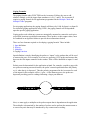
Polarity must be determined for the application at hand. For example, consider a gage with
two probes measuring an outer diameter, the probe’s normal operation defines the polarity
as (+) when the tip is depressed. Thus the polarity programmed in the Accusetter for each
of our inputs for this example will be (+) plus. As the diameter grows, the probes are
depressed providing positive readings indicating a larger part diameter.
Next, we must apply a multiplier to the probes outputs that is dependant on the application.
The multiplier is determined by the number of probes used to perform the measurement or
to correct any ratio that may be introduced by any contact arms or tooling.
3-10
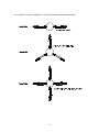
An example of various multipliers as related to diameter measurement follows:
3-11
The last consideration to complete the formula is the gaging function. See examples
below:
3-12
Multiple Check Formulas
If the Accusetter is programmed for multiple check operation then the results of checks 1,
2, and/or 3 can be combine algebraically. For an example of a multiple check application
consider and air plug that measures a part ID at two elevations. The large diameter is
measured with input A and displays the large diameter size as check #1. The small
diameter is measured with input B and displays the small diameter size as check #2. To
display the part taper check #3 can be defined as a multiple check to display the results of
check #1 minus check #2.
Check #1, Large Diameter
Function = AVG
Formula = A x (+)1.000
Check #2, Small Diameter
Function = AVG
Formula = B x (+)1.000
Check #3, Multiple Check, Taper
Function = AVG
Formula = CHK1 x (+)1.000 + CHK2 x (-)1.000
3-13
Selecting Full Scale Value
All Edmunds air tooling is marked with the full scale range it was intended to work with.
Since overall range of air tooling is limited, our tooling is designed to operate on one scale
only. Random switching of ranges may affect the performance and linearity of the tooling.
Using tooling manufactured for a type of system other than Edmunds’ back-pressure bleed
system may require trial and error to determine the optimum air amplification choice for
the most stable and linear readings. The following chart may be helpful is selecting the
proper magnifications.
Marked Range
.050” / 1mm
.020” / .5mm
.010” / .2mm
.005” / .1mm
.002” / .05mm
.001” / .02mm
.0005” / .01mm
.0002” / .005mm
Air Amplification
Not for air use
Not for air use
Low
Low
Medium
High
High
High
3-14
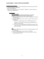
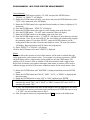
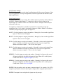
PROGRAMMING - SINGLE CHECK MEASUREMENT
3-15
PROGRAMMING - SINGLE CHECK MEASUREMENT
3-16
PROGRAMMING - SINGLE CHECK MEASUREMENT
Programming SETUP Options
1) With the column in RUN mode, Press the ENTER button and then rotate the ENTER
button until "SETUP" is displayed.
2) Press the ENTER button.
3) Rotate the ENTER button to select "XDUCER", "DEFINE" or "PART NAME" and
then press the ENTER button.
XDUCER Menu
Signal Conditioning
(Note: These parameters will be automatically set by module
recognition for E9310, E9320, E9330, or E9340 modules)
1) Rotate the ENTER button until "SIG COND" is displayed and then press
the ENTER button.
2) Rotate the ENTER button to select "AIR" or "ELEC" and then press the
ENTER button.
a) If "ELEC" was selected then rotate the ENTER button to select
"GAIN 1X" or "GAIN 10X" and then press the ENTER button to
return to the Xducer menu.
b) If "AIR" was selected then rotate the ENTER button to select LOW
MAG, MED MAG, or HIGH MAG and then press ENTER to return
to the Xducer menu.
Scale
1) Rotate the ENTER button until "SCALE" is displayed and then press the
ENTER button.
2) Rotate the ENTER button to select "INCH" or "METRIC".
3) Press the ENTER button and the Accusetter will return to the Xducer
menu and display "SCALE".
3-17
PROGRAMMING - SINGLE CHECK MEASUREMENT
Pol/Mag
1) Rotate the ENTER button until "POL/MAG" is displayed and then press
the ENTER button.
2) Rotate the ENTER button to select "INPUT A" or "INPUT B" and then
press the ENTER button. A numerical value with a polarity (+ or -)sign
will be displayed.
3) Enter the correct polarity and magnification. Refer to the Accusetter
program guide supplied with your gage.
4) After setting the polarity and mag for one input press RST and then
rotate the ENTER button to select the next input to be set up. Repeat
steps 2 - 4.
5) After programming all required inputs press RST until "XDUCER" is
displayed. All Xducer options are now programmed.
How To Enter Numerical Values and polarities
Enter the correct numeral or polarity by pressing the enter button to move
from one decimal place to another. To change numbers or polarity signs
rotate the ENTER button left or right until desired number or sign is
displayed.
DEFINE Menu
1) From Run mode press the ENTER button.
2) Rotate the ENTER button to display "SETUP" and then press ENTER.
3) Rotate the ENTER button to display "DEFINE" and then press ENTER.
Function
1) Rotate the ENTER button until "FUNCTION" is displayed and then
press ENTER.
2) Rotate the ENTER button to select from "BYPASS", "+PEAK", "PEAK", or "TIR". Refer to the Accusetter program guide for the
correct function for a given application.
3) Press the ENTER button and the Accusetter will return to the DEFINE
menu and display "FUNCTION".
3-18
PROGRAMMING - SINGLE CHECK MEASUREMENT
Range
1) Rotate the ENTER button until "RANGE" is displayed and then press
ENTER.
2) Rotate the ENTER button until the desired full scale value is displayed
and then press enter. Refer to the Accusetter program guide for the
correct range for a given application. NOTE: If the scale option of the
Xducer menu is set to INCH then only inch range options will be listed
and if the scale option of the Xducer menu is set to METRIC only
metric ranges will be listed.
Note: .020”/.500mm or .050”/1.00mm ranges should be used for electronic
applications only.
3) After the desired range is displayed press the ENTER button.
4) Rotate the ENTER button to select "DEVIATION" or "ABSOLUTE"
and then press the ENTER button.
5) If deviation was selected then the Accusetter will return to the define
menu and display "RANGE". If Absolute was selected then use the
ENTER button to program the nominal part size. After programming
the nominal size press the RST button until "RANGE" is displayed.
NOTE: If the RANGE is changed the master sizes and part limits must
also be reprogrammed.
Limits
1) Rotate the ENTER button until "LIMITS" is displayed and then press
the ENTER button.
2) Rotate the ENTER button until "MAX" is displayed and then press the
ENTER button.
3) Rotate the ENTER button to drive the bargraph until the max limit is
displayed and press the ENTER button.
4) Rotate the ENTER button until "MIN" is displayed and then press the
ENTER button.
5) Rotate the ENTER button to drive the bargraph until the min limit is
displayed and then press the RST button to display "LIMITS".
3-19
PROGRAMMING - SINGLE CHECK MEASUREMENT
Master
This menu allows the operator to select which masters will be used to
calibrate the gage and to program the correct master values. For example a
two master system uses a MAX and MIN master while a single master
system would use only the ZERO master. The auxiliary (AUX) master is
used to calibrate a TIR check mastered with a single master. Refer to the
Accusetter setup guide to determine what master or masters will be used to
calibrate the gage and refer to the master calibration reports for the actual
master values.
1) Rotate the ENTER button until "MASTER" is displayed and then press
the ENTER button.
2) Rotate the ENTER button until "MAX", "MIN", "AUX", or "ZERO" is
displayed and then press enter.
3) Rotate the ENTER button to select "ON" or "OFF" and then press
ENTER.
NOTE: If the auxiliary master ("AUX") is turned "ON" then "MAX" and
"MIN" are automatically turned "OFF" and if "MAX" or "MIN" is turned
"ON" then "AUX" is automatically turned "OFF".
4) If ON was selected then rotate the ENTER button to drive the bargraph
to the master value listed on the master certification report and then
press ENTER and return to step 2. If OFF was selected then return to
step 2.
5) After all required masters are programmed press RST to display
"MASTER".
Check Name
1) Rotate the ENTER button to display "CHK NAME" and then press
ENTER.
2) "PART 1" will display. Press the ENTER button.
3) The first character will flash. Rotate the ENTER button to change the
character and then press ENTER to move to the next character. Press
RST when done. The programmed name will display. Press RST again
to return to the define menu.
Part Names
Note:The part name of the program can be renamed if desired to store in memory.
1) From the Setup menu, rotate the ENTER button to display "PART NAME".
2) Press the ENTER button. "PART 1" will display.
3) Press the ENTER button. The first character will flash. To change, rotate the ENTER
button left or right until desired character is displayed.
4) Press the ENTER button to move to next character.
5) Press the RST button once, when done. The programmed name will display.
6) Press the RST button once.
3-20
PROGRAMMING - SINGLE CHECK MEASUREMENT
Saving the Program
1) Press the RUN button. "CANCEL" will display.
2) Rotate the ENTER button to display "SAVE" and then press the ENTER button to save
the setup.
3-21
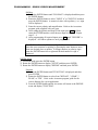
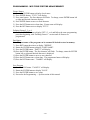
PROGRAMMING - MULTIPLE CHECK MEASUREMENT
3-22
PROGRAMMING - MULTIPLE CHECK MEASUREMENT
3-23
PROGRAMMING - MULTIPLE CHECK MEASUREMENT
Multiple Check Programming
Programming SETUP Options
1) With the column in RUN mode, Press the ENTER button and then rotate the ENTER
button until "SETUP" is displayed.
2) Press the ENTER button.
3) Rotate the ENTER button to select "XDUCER", "DEFINE" or "PART NAME" and
then press the ENTER button.
XDUCER Menu
Signal Conditioning
(Note: These parameters will be automatically set by module
recognition for E9310, E9320, E9330, or E9340 modules)
1) Rotate the ENTER button until SIG COND is displayed and then press
the ENTER button.
2) Rotate the ENTER button to select "AIR" or "ELEC" and then press the
ENTER button.
a) If "ELEC" was selected then rotate the ENTER button to select
"GAIN 1X" or "GAIN 10X" and then press the ENTER button to
return to the Xducer menu.
b) If "AIR" was selected then rotate the ENTER button to select LOW
MAG, MED MAG, or HIGH MAG and then press ENTER to return
to the Xducer menu.
Scale
1) Rotate the ENTER button until SCALE is displayed and then press the
ENTER button.
2) Rotate the ENTER button to select "INCH" or "METRIC".
3) Press the ENTER button and the Accusetter will return to the Xducer
menu and display "SCALE".
3-24
PROGRAMMING - MULTIPLE CHECK MEASUREMENT
Pol/Mag
1) Rotate the ENTER button until "POL/MAG" is displayed and then press
the ENTER button.
2) Rotate the ENTER button to select "INPUT A", "INPUT B", "INPUT
C", or "INPUT D" and then press the ENTER button. A numerical value
with a polarity (+ or -) sign will be displayed.
3) Enter the correct polarity and magnification. Refer to the Accusetter
program guide for the correct value and polarity.
4) After setting the polarity and mag for one input press RST and then
rotate the ENTER button to select the next input to be set up. Repeat
steps 2 - 4.
5) After programming all required inputs press RST until XDUCER is
displayed. All Xducer options are now programmed.
How To Enter Numerical Values and polarities
Enter the correct numeral or polarity by pressing the enter button to move from
one decimal place to another. To change numbers or polarity signs rotate the
ENTER button left or right until desired number or sign is displayed.
DEFINE Menu
# CHKS
Use this menu to define the total number of checks to be programmed from 1 to 4.
1) Rotate the ENTER button until "#CHKS" is displayed and then press ENTER.
2) Rotate the ENTER button to select "#CHK=1", "#CHK=2", "#CHK=3", or
"#CHK=4" and then press ENTER to return to the define menu.
3-25
PROGRAMMING - MULTIPLE CHECK MEASUREMENT
CHK 1, CHK 2, CHK 3, CHK 4
Select the check that is to be set up by:
1) Rotate the ENTER button until the desired check number is displayed and then
press ENTER.
2) For each check in the gage setup the FUNCTION, RANGE, LIMITS,
MASTERS, and CHECK NAME per the following instructions.
Function
1) Rotate the ENTER button until "FUNCTION" is displayed and then
press ENTER.
2) Rotate the ENTER button to select from BYPASS, AVG, +PEAK, PEAK, TOL CHK, or TIR. Refer to the Accusetter program guide for
the correct function for a given application and then press ENTER.
3) Rotate the ENTER button to select FORMULA or MPL CHK and then
press ENTER.
NOTE: Refer to the Accusetter setup guide for the gage formula or
multiple check formula to be programmed for this check.
Use the FORMULA menu if the check is a result of one or more gage
inputs and use the MPL CHK formula if this check a combination of the
results from two or more other checks.
Formula
1) Rotate the ENTER button to select input A, B, C, or D and then
press ENTER.
2) A numerical value with a polarity sign (+ or -) will display. Enter
the correct magnification numeral. If this input is not being used,
change number to 0. Enter the correct polarity by pressing the
enter button to move to the + or - position and rotate enter button
to select your choice.
3) Press the RST button to return to the formula menu and rotate
the ENTER button to select the next input, if any, used on the
current check and repeat steps 1 - 2. When all inputs for the
current check have been setup press the RST button until
"FUNCTION" is displayed.
3-26
PROGRAMMING - MULTIPLE CHECK MEASUREMENT
MPL CHK
1) Rotate the ENTER button to select "CHK 1", "CHK 2", or "CHK
3" and then press ENTER.
2) A numerical value with a polarity sign (+ or -) will display. Enter
the correct magnification numeral. If this check is not being
used, change number to 0. Enter the correct polarity by pressing
the enter button to move to the + or - position and rotate enter
button to select your choice.
3) Press the RST button to return to "CHK X" and rotate the
ENTER button to select the next check, if any, used on the
current check and repeat steps 1 - 2. When all check for the
current multiple check have been setup press the RST button
until FUNCTION is displayed.
Range
1) Rotate the ENTER button until "RANGE" is displayed and then press
ENTER.
2) Rotate the ENTER button until the desired full scale value is displayed
and then press enter. Refer to the Accusetter program guide for the
correct range for a given application. NOTE: If the scale option of the
Xducer menu is set to INCH then only inch range options will be listed
and if the scale option of the Xducer menu is set to METRIC only
metric ranges will be listed.
Note: .020”/.500mm or .050”/1.00mm ranges should be used for electronic
applications only.
3) After the desired range is displayed press the ENTER button.
4) Rotate the ENTER button to select "DEVIATN" or "ABSOLUTE" and
then press the ENTER button.
5) If "Deviation" was selected then the Accusetter will return to the define
menu and display "RANGE". If "Absolute" was selected then use the
ENTER button to program the nominal part size. After programming
the nominal size press the RST button until RANGE is displayed.
NOTE: If the RANGE is changed the master sizes and part limits must
also be reprogrammed.
3-27
PROGRAMMING - MULTIPLE CHECK MEASUREMENT
Limits
MAX, MIN, +APPR, -APPR
1) Rotate the ENTER button until "LIMITS" is displayed and then
press the ENTER button.
2) Rotate the ENTER button until "MAX", "MIN", "+APPR", or" APPR" is displayed and then press the ENTER button.
3) Rotate the ENTER button to select whether the limit will be "ON" or
"OFF" and then press ENTER.
4) Rotate the ENTER button to drive the bargraph until the limit value
is displayed and press the ENTER button.
5) Repeat steps 2 - 4 for any limits that are required.
CLASS
1) Rotate the ENTER button until "LIMITS" is displayed and then
press the ENTER button.
2) Rotate the ENTER button until "CLASS" is displayed and then press
ENTER.
3) Rotate the ENTER button to select "EQUAL" or "SELECT" and
then press ENTER.
Note: If you chose "EQUAL", the Accu-Setter will automatically
program the classes after the first class size is programmed. If you
chose SELECT, the operator can program each class size
independently.
4) "QTY" with a numerical value will display. Rotate ENTER button
until desired number of classes is displayed, 39 maximum, and press
the ENTER button.
5) "STRT. PT." will display. Rotate the ENTER button to set the
starting point of first class and then press the ENTER button.
6) "CLASS" with a numerical value will display. Rotate the ENTER
button to set the ending point of the first class and then press the
ENTER button.
7) "CLASS 02" will display if more than one class has been selected.
If EQUAL was selected in step 3 then the Accusetter will
automatically program the remaining classes. If SELECT was
chosen in step 3 then rotate the ENTER button to set the ending
point of the next class, press ENTER and repeat until all classes
have been programmed.
8) Press the RST button until "LIMITS" is displayed to return to the
define, checks menu.
3-28
PROGRAMMING - MULTIPLE CHECK MEASUREMENT
Master
This menu allows the operator to select which masters will be used to
calibrate the gage and to program the correct master values. For example a
two master system uses a MAX and MIN master while a single master
system would use only the ZERO master. The auxiliary (AUX) master is
used to calibrate a TIR check mastered with a single master. Refer to the
Accusetter setup guide to determine what master or masters will be used to
calibrate the gage and refer to the master calibration reports for the actual
master values.
NOTE: If a check is programmed as a "Multiple Check" then master
values do not need to be programmed and "MASTER" will not appear
as a choice on the check setup menu.
1) Rotate the ENTER button until "MASTER" is displayed and then press
the ENTER button.
2) Rotate the ENTER button until "MAX", "MIN", "AUX", or "ZERO" is
displayed and then press enter.
3) Rotate the ENTER button to select "ON" or "OFF" and then press
ENTER.
NOTE: If the auxiliary master ("AUX") is turned "ON" then "MAX"
and "MIN" are automatically turned "OFF" and if "MAX" or "MIN"
is turned "ON" then "AUX" is automatically turned "OFF".
4) If "ON" was selected then rotate the ENTER button to drive the
bargraph to the master value listed on the master certification report and
then press ENTER and return to step 2. If "OFF" was selected then
return to step 2.
5) After all required masters are programmed press RST to return to the
define menu.
Check Name
1) Rotate the ENTER button to display "CHK NAME" and then press
ENTER.
2) "PART 1" will display. Press the ENTER button.
3) The first character will flash. Rotate the ENTER button to change the
character and then press ENTER to move to the next character. Press
RST when done. The programmed name will display. Press RST again
to return to the define menu.
Part Names
Note:The part name of the program can be renamed if desired to store in memory.
1) From the Setup menu, rotate the ENTER button to display "PART NAME".
2) Press the ENTER button. "PART 1" will display.
3) Press the ENTER button. The first character will flash. To change, rotate the ENTER
button left or right until desired character is displayed.
4) Press the ENTER button to move to next character.
5) Press the RST button once, when done. The programmed name will display.
6) Press the RST button once.
3-29
PROGRAMMING - MULTIPLE CHECK MEASUREMENT
Saving the Program
1) Press the RUN button. "CANCEL" will display.
2) Rotate the ENTER button to display "SAVE" and then press the ENTER button to save
the setup.
3-30
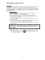
PROGRAMMING - MULTIPLE FIXTURE MEASUREMENT
3-31
PROGRAMMING - MULTIPLE FIXTURE MEASUREMENT
3-32
PROGRAMMING - MULTIPLE FIXTURE MEASUREMENT
Multiple Fixture Programming
Programming SETUP Options
1) With the column in RUN mode, Press the ENTER button and then rotate the
ENTER button until "SETUP" is displayed.
2) Press the ENTER button.
3) Rotate the ENTER button to select "XDUCER", "DEFINE" or "PART NAME" and
then press the ENTER button.
XDUCER Menu
Signal Conditioning
(Note: These parameters will be automatically set by module
recognition for E9310, E9320, E9330, or E9340 modules)
1) Rotate the ENTER button until "SIG COND" is displayed and then press
the ENTER button.
2) Rotate the ENTER button to select "AIR" or "ELEC" and then press the
ENTER button.
a) If "ELEC" was selected then rotate the ENTER button to select
"GAIN 1X" or "GAIN 10X" and then press the ENTER button to
return to the Xducer menu.
b) If "AIR" was selected then rotate the ENTER button to select LOW
MAG, MED MAG, or HIGH MAG and then press ENTER to return
to the Xducer menu.
Scale
1) Rotate the ENTER button until "SCALE" is displayed and then press the
ENTER button.
2) Rotate the ENTER button to select "INCH" or "METRIC".
3) Press the ENTER button and the Accusetter will return to the Xducer
menu and display "SCALE".
3-33
PROGRAMMING - MULTIPLE FIXTURE MEASUREMENT
Pol/Mag
1) Rotate the ENTER button until "POL/MAG" is displayed and then press
the ENTER button.
2) Rotate the ENTER button to select INPUT A, INPUT B, INPUT C, or
INPUT D and then press the ENTER button. A numerical value with a
polarity (+ or -)sign will be displayed.
3) Enter the correct polarity and magnification. Refer to the Accusetter
program guide for the correct value and polarity.
4) After setting the polarity and mag for one input press RST and then
rotate the ENTER button to select the next input to be set up. Repeat
steps 2 - 4.
5) After programming all required inputs press RST until XDUCER is
displayed. All Xducer options are now programmed.
How To Enter Numerical Values and polarities
Enter the correct numeral or polarity by pressing the enter button to move from
one decimal place to another. To change numbers or polarity signs rotate the
ENTER button left or right until desired number or sign is displayed.
DEFINE
1) Rotate the ENTER button to display "DEFINE".
2) Press the ENTER button. "# FXTS" will display.
3) Press the ENTER button.
5) Rotate the ENTER button to display the number of fixtures in your application.
6) Press the ENTER button to select the correct number of checks. "#FXTS" will
display.
Defining Fixture 1
1) Rotate the ENTER button to display "FXT 1".
Select Function
1) Press the ENTER button to display "FUNCTION".
2) Press the ENTER button.
3) Either "BYPASS", "+PEAK", "-PEAK", "TIR", "AVG", or "TOL CHK" will
display. Rotate the ENTER button to display the proper function for your
application.
4) Press the ENTER button to select.
Program Formula
1) "FORMULA" will display.
2) Press the ENTER button. "INPUT A" will display.
3) Rotate the ENTER button to display the INPUT to be programmed for
FIXTURE #1. You will have a choice of A, B, C, or D.
4) Press the ENTER button. A numerical value with a polarity sign (+ or -) will
display.
5) Enter the correct magnification numeral. (As standard, 1 is the correct number.
If this input is not being used, change number to 0).
3-34
PROGRAMMING - MULTIPLE FIXTURE MEASUREMENT
6) Enter the correct polarity by pressing the enter button to move to the + or position and rotate ENTER button to select your choice. (As standard, it should
be + polarity).
7) Press RST button to display "INPUT A".
8) If not using any other inputs, set numerical values for those not in use to 0 by
using the same procedure described in steps 4. - 9.
9) If other inputs need to be programmed, follow the same procedure described in
steps 4. - 9.
10) Press the RST button three times to display "FUNCTION".
Select Range
1) Rotate the ENTER button to display "RANGE".
2) Press the enter button. Either one of 8 full scale ranges will display:
a) .0002” / .005mm
b) .0005” / .010mm
c) .001” / .020mm
d) .002” / .050mm
e) .005” / .100mm
f) .010” / .200mm
g) .020” / .500mm
h) .050” / 1.000mm
Note: .020”/.500mm and .050”/1.00mm ranges should be used for electronic
applications only.
3) Rotate the enter button to display the range you need and then press the ENTER
button to select.
4) Either "DEVIATN" or "ABSOLUTE" will display.
5) Rotate the ENTER button to display your choice and then press the ENTER
button.
a) If you choose DEVIATN, RANGE will display
b) If you choose ABSOLUTE, enter the actual nominal size of the
measurement.
6) Press RST button three times to display "RANGE".
NOTE: If the RANGE is changed the master sizes and part limits must
also be reprogrammed.
3-35
PROGRAMMING - MULTIPLE FIXTURE MEASUREMENT
Select Limits
1) Rotate the ENTER button to display LIMITS.
2) Press the ENTER button.
MAX/MIN
1) "MAX" will display.
2) Press the ENTER button. "ON" or "OFF" will display.
3) Rotate the ENTER button to display ON and then press the ENTER button.
4) Rotate the ENTER button until the maximum size or deviation is displayed.
5) Position the upper mechanical pointer at that location on the bargraph display. To move
the pointer, loosen the thumbscrew.
6) Press the ENTER button. "MAX" will display.
7) Rotate the ENTER button to display "MIN".
8) Press the ENTER button. "ON" or "OFF" will display.
9) Rotate the ENTER button to display "ON" and then press the ENTER button.
10) Rotate the ENTER button until the minimum size or deviation is displayed.
11) Position the lower mechanical pointer at that location on the bargraph display.
12) Press the ENTER button.
13) "MIN" will display.
Approach (Optional)
1) Rotate the ENTER button to display "+APPRCH".
2) Press the ENTER button. "ON" or "OFF" will display.
3) Rotate the ENTER button to display your choice. (Select ON if using this limit
function. Select OFF if not using this limit function).
4) Press the ENTER button.
5) If ON, rotate the enter button until the +APPRCH size or deviation is displayed and
then press the ENTER button.. "+ APPRCH" will display.
6) Rotate the ENTER button to display "-APPRCH". Press the ENTER button "ON" or
"OFF" will display.
7) Rotate the ENTER button to display your choice. (Select ON if using this limit
function. Select OFF if not using this limit function). Press the enter button to select.
8) If ON, rotate the enter button to display the "-APPRCH" numerical value.
9) Press the ENTER button. "- APPRCH" will display.
3-36
PROGRAMMING - MULTIPLE FIXTURE MEASUREMENT
Class (Optional)
1) Rotate the ENTER button to display "CLASS" and press the ENTER button.
"EQUAL" or "SELECT" will display.
2) Rotate the ENTER button to display your choice and press the ENTER button to select.
"QTY" with a numerical value will display.
3) Rotate the ENTER button left or right until desired number of classes is displayed. (39
maximum).
4) Press the ENTER button. "STRT PT" will display.
5) Rotate the ENTER button left or right to set the starting point of the first class.
6) Press the ENTER button. "CLASS" with a numerical value will display.
7) Rotate the ENTER button to set the ending point of the first class.
8) Press the ENTER button to select. "CLASS 02" will display if more than one class has
been selected. Note: If you chose EQUAL, the Accu-Setter will automatically program
the remaining classes. If you chose SELECT, rotate the ENTER button to set the
ending point of the next class. Press the enter button to select. The next class number
will display. Repeat procedure until all classes are programmed.
9) Either "SELECT" or "EQUAL" will display.
10) Press the RST button twice until "LIMITS" is displayed.
Master
This menu allows the operator to select which masters will be used to calibrate the gage
and to program the correct master values. For example a two master system uses a MAX
and MIN master while a single master system would use only the ZERO master. The
auxiliary (AUX) master is used to calibrate a TIR check mastered with a single master.
Refer to the Accusetter setup guide to determine what master or masters will be used to
calibrate the gage and refer to the master calibration reports for the actual master values.
1) Rotate the ENTER button until "MASTER" is displayed and then press the ENTER
button.
2) Rotate the ENTER button until "MAX", "MIN", "AUX", or "ZERO" is displayed and
then press enter.
3) Rotate the ENTER button to select "ON" or "OFF" and then press ENTER.
4) NOTE: If the auxiliary master ("AUX") is turned "ON" then "MAX" and "MIN" are
automatically turned "OFF" and if "MAX" or "MIN" is turned "ON" then "AUX" is
automatically turned "OFF".
5) If "ON" was selected then rotate the ENTER button to drive the bargraph to the master
value listed on the master certification report and then press ENTER and return to step
2. If "OFF" was selected then return to step 2.
6) After all required masters are programmed press RST to return to the define menu.
3-37
PROGRAMMING - MULTIPLE FIXTURE MEASUREMENT
Fixture Names
1) Rotate the ENTER button to display check name.
2) Press ENTER button. "FXT 1" will display.
3) Press enter button. The first character will flash. To change, rotate ENTER button left
or right until desired character displays.
4) Press ENTER button to move to next character.
5) Press the RST button twice when done. Fixture name will display.
6) Press the RST button twice to display "FXT 1".
Defining Fixture 2, 3, or 4
1) Rotate the ENTER button to display FXT 2, 3, or 4 and follow the same programming
procedure beginning with “Defining Fixture 1” section until all fixtures are
programmed.
Part Names
Note:The part name of the program can be renamed if desired to store in memory.
7) Press RST button three times to display "DEFINE".
8) Rotate the ENTER button to display "PART NAME".
9) Press the ENTER button. "PART 1" will display.
10) Press the ENTER button. The first character will flash. To change, rotate the ENTER
button left or right until desired character is displayed.
11) Press the ENTER button to move to next character.
12) Press the RST button once, when done. The programmed name will display.
13) Press the RST button once. "NAMES" will display.
Save Program
1) Press the RUN button. "CANCEL" will display.
2) Rotate the ENTER button to display "SAVE".
3) Press the ENTER button to save setup.
4) Proceed to the Programming — System section of this manual.
3-38
PROGRAMMING - SYSTEM OPTIONS
Programming SYSTEM Options
This area of programming allows you to conduct Accu-Setter system tests, program
information downloading (communication), passwords, check names, the auto reset timer,
and part databases. If you will not be using any of these features, proceed to the Calibration
section of this manual.
To access the system menu use the following procedure:
1) From Run mode, press the ENTER button and then rotate the ENTER button until
"SYSTEM" is displayed.
2) Press the ENTER button. If a password is required the Accusetter will prompt the
operator to enter the password to access the system menu. If no password is
programmed the Accusetter will proceed to the system menu.
TESTS Menu
Note: This is a hardware check. The alphanumeric display will prompt you through
various tests.
1) Rotate the ENTER button until "TESTS" is display and then press ENTER.
2) The Accu-Setter version number will scroll across the alphanumeric display.
Press the ENTER button.
3) "RAM TESTS" will display. Cycle 1 - 9 will process automatically, the range
LEDs will light up one at a time, the bargraph will cycle thru three colors, (red,
green, yellow), and the alphanumeric display will cycle for light intensity and
numerical values. After the automatic tests are completed "KEY TEST" will be
displayed. Proceed with the key test as described below. If the key test is not
performed the automatic test will repeat.
4) Press any key, RUN, CAL, RST, INPUTS, RANGE, or PAR DB. IF the key is
working properly then the key name will appear in the alphanumeric display.
5) Press the RUN key. "CANCEL" will display. Press the ENTER button to exit
the test sequence.
3-39
PROGRAMMING - SYSTEM OPTIONS
COMM Menu
The communications menu allows the operator to program the Accusetter to download data
to, or receive communications from, an external device and ,with multiple check or
multiple fixture programs, to setup signals to buss to other columns. NOTE: See section
4.4, Communication in the Advanced Operation section of the manual for additional
technical specification.
External Device Setup
1) Rotate the enter button to display "COMM" and then press ENTER.
2) RS-232 will display. Press the ENTER button.
3) Rotate the ENTER button to select "DEVICE" and then press ENTER.
4) Rotate the ENTER button to select "NO COMM", "PRINTER", or "DATA
COL" and then press ENTER.
5) "DEVICE" will display. Rotate the ENTER button to display "BAUD" and
then press ENTER.
6) Rotate the ENTER button to select 600, 1200, 2400, 4800, 9600, or 19,200 and
then press ENTER. NOTE: The default baud rate is 600.
7) "BAUD" will display. Rotate the enter button to display "STATION" and then
press ENTER.
NOTE: If multiple columns are daisy chained by the RS-232C connector then
communication to a specific column requires the identification of the column
by station number. Use the following procedure to program the column
"Station" number.
8) "STAT" with a numerical value will display. Rotate the enter button to display
desired station number, 0 to 9, to identify the column and then press ENTER.
9) "STATION" will display. Press the RST button to return to the system menu,
"COMM" will be displayed.
3-40
PROGRAMMING - SYSTEM OPTIONS
Buss In/Buss Out Setup
Note: For multiple check and multiple fixture programs BUSS IN and BUSS OUT
options are available, for column to column communications. These signal are used
with the I/O "A" and "B" 25 pin connections.
1) From the COMM menu rotate the enter button to display "BUS OUT" and then
press ENTER.
2) Rotate the ENTER button to select the name of the check or fixture to be bussed
out and then press ENTER.
3) "BUS OUT" will display. Rotate the enter button to display "BUS IN" and
press the ENTER button.
4) Rotate the ENTER button to select "INPUT C" or "INPUT D" and press the
ENTER button.
5) Rotate the ENTER button to select "AIR" if the signal to be bussed in is from an
air gage or "ELEC" if the signal to be bussed in is from an electronic gage.
6) Press the ENTER button.
7) Press the RST button. If a second bussed in signal is to be set up repeat steps 4
- 6.
8) When all inputs have been setup press the RUN button.
9) Rotate the ENTER button to display "SAVE" and then press ENTER to save the
current setup.
3-41
PROGRAMMING - SYSTEM OPTIONS
SECURITY Menu
1) Rotate the enter button to display "SECURITY" and then press the ENTER
button.
2) "MAST" with a numerical value will display. Note: Master password must be
entered now to allow programming your own password. Contact Edmunds
Gages if master password is unknown.
3) Press the ENTER button after entering the master password.
4) "PASS" with a numerical value will display. Enter your password number.
Note: if no password is required, program 000.
5) Press the ENTER button to return to the system menu, "SECURITY" will
display.
How To Enter Numerical Values
Enter the correct numeral by pressing the enter button to move from one decimal
place to another. To change numbers rotate enter button left or right until desired
number is displayed.
AUTO RST Menu
If the gaging application uses a +PEAK, -PEAK, or TIR function the display will
normally stay latched on the peak reading until the RST button is pressed. The auto
reset option allows the operator to program a timer to automatically reset the
display without hitting the RST button. To program the auto reset feature from the
system menu:
1) Rotate the enter button to display "AUTO RST" and then press ENTER.
2) Rotate the enter button to select "ON" or "OFF" and then press the ENTER
button.
3) If OFF was selected then the Accusetter will return to the system menu and
display "AUTO RST". If ON was selected then "DELAY" with a numeric
value will be displayed.
4) Rotate the ENTER button to display your choice of 0 - 10 seconds time delay.
5) Press the ENTER button and ON will be displayed.
6) Press the RST button to return to the system menu and "AUTO RST" will be
displayed.
3-42
PROGRAMMING - SYSTEM OPTIONS
AUTO AIR Menu (Optional)
If the optional automatic air shutoff is installed then this menu is available to
program the time delay before air shutoff or to disable the auto air shutoff.
See the Auto Air Shutoff in the Advanced Operation section 4.6 for more
information.
PART DB
The part database menu allows the operator to select an existing program to load or
save the current setup for future use
1) Rotate the ENTER button to display "PART DB" or press the PART DB
shortcut button.
2) Press the ENTER button.
3) "PART" and a number will be displayed.
4) Rotate the ENTER button to display the desired setup number.
5) Press the ENTER button.
6) "SELECT" will display.
7) Rotate the ENTER button to choose from "SAVE", "CLEAR", or "SELECT".
8) Press the ENTER button.
9) "PART" and a number will be displayed.
10) Press the RST button once. "PART DB" will be displayed.
RANGE
If Range is "ON" then the range menu is accessible from the level 0 menu.
1) From the System menu, rotate the ENTER button to select "RANGE OP" and
then press ENTER.
2) Rotate the ENTER button to select "ON" or "OFF" and then press ENTER.
3) Press the RUN button.
4) Rotate the ENTER button to select "SAVE" and then press ENTER.
3-43
3.4 Input Setup
Setting A/E Mag and Zero for Air Gage
NOTE: Inputs MUST be setup from the Calibration, Inputs menu not in RUN mode.
In Run mode the master corrections are applied. In Calibration mode the raw input
readings are displayed.
If the gage tooling is an airplug or air ring using an (1) channel or (2) channel A/E module
use the following procedure to set zero and magnification for each input(s) using a set of
max and min masters.
1) Press the CAL button.
2) Rotate the ENTER button until "INPUTS" is displayed and then press the ENTER
button.
3) Rotate the ENTER button to select the full scale value to be displayed on the bargraph
and then press the ENTER button.
4) Rotate the ENTER button to select an input, check, or fixture to display as a live
reading on the bargraph. Note: The live input, check, or fixture readings are always
displayed as deviations from nominal.
5) Load the MAX master into gage position.
6) Refer to the master calibration report to determine the master value of the MAX master.
7) Adjust the ZERO knob on the signal conditioning module until the digital display reads
the master value of the MAX master for the check being setup from the calibration
report.
8) Remove the MAX master and load the MIN master into gage position.
9) Calculate the difference between the reading with the MIN master loaded and the
reading with the MAX master from step 7.
a) If the calculated difference is less than the actual difference between the MAX and
MIN master values from the calibration sheet for the check being setup, the
magnification needs to be increased. This is done by turning the mag knob
clockwise.
b) If the calculated difference is greater than the actual difference between the MAX and
MIN master values from the calibration sheet for the check being setup, the
magnification needs to be decreased. This is done by turning the mag knob counter
clockwise.
NOTE: Use a factor of 3X for adjusting the display readings. For example: If the
displayed reading is +.0005 and the calibrated value is +.0001 the difference is .0004
greater. Therefore, you turn the "MAG" knob counter clockwise so that the reading
changes by .0012.
IMPORTANT: THE DIRECTION YOU TURN THE MAG KNOB DETERMINES
WHETHER YOU ARE INCREASING OR DECREASING THE
MAGNIFICATION. YOU SHOULD BE CONCERNED WITH HOW MUCH THE
DISPLAY CHANGES, NOT THE DIRECTION THE NUMBERS CHANGE!
(Cont)
3-44
For example, for the above example after turning the mag knob the displayed reading
may be (+.0005) + (.0012) = +.0017 or it could read (+.0005) - (.0012) = -.0007. This
depends on the polarity of the check.
10) After adjusting the mag knob, turn the zero knob in the same direction as the mag knob to
adjust the displayed reading to equal the deviation of the MIN master value on the
calibration sheet.
11) Remove the MIN master and load the MAX master onto the gage.
12) Repeat steps 5 through 12 until the displayed readings for the each master corresponds to
the max and min master deviation values on the calibration sheet for the check being
setup.
3-45
Setting up LVDT Inputs
Prior to calibrating the gage the LVDT inputs must be properly positioned in the tooling.
Use the following procedure to setup each LVDT input.
1) Press the CAL button.
2) Rotate the ENTER button until "INPUTS" is displayed and then press ENTER.
3) Rotate the ENTER button to select the desired full scale value to use for input setup
and then press ENTER.
4) Rotate the ENTER button until the input to be setup is displayed. The bargraph and
alphanumeric display will show a live reading of the selected input.
5) If the gage uses two masters for calibration load the MAX master into gage position. If
the gage uses a single zero master for calibration load the ZERO master into gage
position.
6) Determine the target size that the LVDT will be set to using the known calibrated size
of the master from the master certification report and the total number of probes used to
measure the specific feature. Use the following chart as a guide, however,
individual gage tooling varies depending on many factors and the actual target
size may be different depending on the tooling configuration. Refer to
documentation supplied with the gage tooling for additional information.
Number of Probes
1
2
3
4
Target Setup Size
100% of master value
50% of master value
33% of master value
25% of master value
7) Loosen the clamping screw holding the LVDT in position and, while observing the
bargraph display, reposition the LVDT until a value as close to the target setup size as
possible is displayed.
8) Tighten the clamp screw to secure the LVDT. NOTE: Do not over tighten the
clamp screw.
3-46
3.5 Calibration
NOTE: Prior to performing the automatic calibration procedure, the Air to Electric or
LVDT inputs need to be properly setup, see Input Setup.
Single Check Application
Two Master System
1) Press the CAL button.
2) Rotate the ENTER button until "MASTER" is displayed and then press ENTER. The
check name will be displayed.
3) Press the ENTER button. "INS MAX" will be displayed.
4) Place the MAX master into gage position and press ENTER. "GAGE MAX" will be
displayed.
5) Press the ENTER button. The MAX master will be gaged and then the display will
update to "INS MIN".
6) Remove the MAX master, place the MIN master into gage position and press ENTER.
"GAGE MIN" will be displayed.
7) Press the ENTER button. The MIN master will be gaged and then the display will
update to "MASTERED" if the calibration was successful. If the calibration was
successful the gage is ready to measure parts, see Operation. Remove the MIN master
and press RUN. If the calibration was not completed successfully then see the
Troubleshooting section of this manual.
Zero Master Systems
1) Press the CAL button.
2) Rotate the ENTER button until "MASTER" is displayed and then press ENTER. The
check name will be displayed.
3) Press the ENTER button. "INS ZERO" will be displayed.
4) Place the ZERO master into gage position and press ENTER. "GAGE ZERO" will be
displayed.
5) Press the ENTER button. The ZERO master will be gaged and then the display will
update to "MASTERED" if the calibration was successful. If the calibration was
successful the gage is ready to measure parts, see Operation. Remove the ZERO
master and press RUN. If the calibration was not completed successfully then see the
Troubleshooting section of this manual.
3-47
Auxiliary Master Systems
1) Press the CAL button.
2) Rotate the ENTER button until "MASTER" is displayed and then press ENTER. The
check name will be displayed.
3) Press the ENTER button. "INS AUX" will be displayed.
4) Place the Auxiliary master into gage position and press ENTER. "GAGE AUX" will
be displayed.
5) Press the ENTER button and rotate the auxiliary master as required. The Auxiliary
master will be gaged and then the display will update to "MASTERED" if the
calibration was successful. If the calibration was successful the gage is ready to
measure parts, see Operation. Remove the ZERO master and press RUN. If the
calibration was not completed successfully then see the Troubleshooting section of this
manual.
3-48
Multiple Check Applications
In a multiple check program the Accusetter II will automatically turn mastering "ON" for
all checks with masters programmed when calibration mode is activated. During the
calibration procedure the Accusetter will automatically detect which checks are returning
valid results, that is the inputs are not off scale and a different max and min reading is
detected, and will record the calibration results for those checks. If all of the checks are not
calibrated then the Accusetter II will prompt the operator to continue the calibration
procedure until all checks have been mastered or the operator presses the RUN button. If
all checks have not been successfully mastered "NOT MAST" will display when the RUN
button is pressed.
Use the following procedure to perform the gage calibration:
1) Press the CAL button.
2) Rotate the ENTER button until "MASTER" is displayed and then press ENTER. "INS
MAX" will be displayed.
3) Place the MAX master(s) into gage position and press ENTER. "GAGE MAX" will be
displayed.
4) Press the ENTER button. The MAX master(s) will be gaged and then the display will
update to "INS MIN".
5) Remove the MAX master(s), place the MIN master(s) into gage position and press
ENTER. "GAGE MIN" will be displayed.
6) Press the ENTER button. The MIN master(s) will be gaged. If only some of the checks
programmed with Max/Min masters were mastered then the Accusetter II will prompt
the operator to "INS MAX" to continue the calibration sequence by mastering the
remaining checks with Max/Min masters. Repeat steps 3 - 6 until all checks have been
mastered. NOTE: By rotating the ENTER button when the Accusetter II prompts the
operator to "INS MAX" the check numbers that still need to be calibrated will be
displayed.
7) If any checks are programmed with auxiliary masters, then "INS AUX" will be
displayed. Load the auxiliary master into gage position.
8) Press the ENTER button and "GAGE AUX" will be displayed.
9) Rotate the auxiliary master as required and then press ENTER.
10) The display will update to "MASTERED" if the calibration of all checks was
completed successfully.
a) If there are no ZERO masters programmed then the gage is ready to measure
parts. Press RUN and see Operation. If there are ZERO masters programmed
see Zero master calibration below.
3-49
Zero Master Calibration
1) From RUN mode, press the CAL button.
2) Rotate the ENTER button until "ZERO" is displayed and then press ENTER. "INS
ZERO" will be displayed.
NOTE: All checks that are programmed with a ZERO master will be turned "ON"
by default and will therefore be gaged at the same time. If the ZERO masters are to
be gaged separately then the checks must be turned "OFF" manually from the "CHK
SEL" menu.
3) Place the ZERO master into gage position and press ENTER. "GAGE ZERO" will be
displayed.
4) Press the ENTER button. The ZERO master will be gaged and then the display will
update to "MASTERED" if the calibration was successful. If the calibration was
successful the gage is ready to measure parts, see Operation. Remove the ZERO
master and press RUN. If the calibration was not completed successfully then see the
Troubleshooting section of this manual.
3-50
Multiple Fixture Application
In a multiple fixture program the Accusetter II will automatically turn mastering "ON" for
all checks with masters programmed when calibration mode is activated. During the
calibration procedure the Accusetter will automatically detect which checks are returning
valid results, that is the inputs are not off scale and a different max and min reading is
detected, and will record the calibration results for those checks. If all of the checks are not
calibrated then the Accusetter II will prompt the operator to continue the calibration
procedure until all checks have been mastered or the operator presses the RUN button. If
all checks have not been successfully mastered "NOT MAST" will display when the RUN
button is pressed.
Use the following procedure to perform the gage calibration:
1) Press the CAL button.
2) Rotate the ENTER button until "MASTER" is displayed and then press ENTER. "INS
MAX" will be displayed.
3) Place the MAX master(s) into gage position and press ENTER. "GAGE MAX" will be
displayed.
4) Press the ENTER button. The MAX master(s) will be gaged and then the display will
update to "INS MIN".
5) Remove the MAX master(s), place the MIN master(s) into gage position and press
ENTER. "GAGE MIN" will be displayed.
6) Press the ENTER button. The MIN master(s) will be gaged. If only some of the checks
programmed with Max/Min masters were mastered then the Accusetter II will prompt
the operator to "INS MAX" to continue the calibration sequence by mastering the
remaining checks with Max/Min masters. Repeat steps 3 - 6 until all checks have been
mastered. NOTE: By rotating the ENTER button when the Accusetter II prompts the
operator to "INS MAX" the check numbers that still need to be calibrated will be
displayed.
7) If any checks are programmed with auxiliary masters, then "INS AUX" will be
displayed. Load the auxiliary master into gage position.
8) Press the ENTER button and "GAGE AUX" will be displayed.
9) Rotate the auxiliary master as required and then press ENTER.
10) The display will update to "MASTERED" if the calibration of all checks was
completed successfully.
b) If there are no ZERO masters programmed then the gage is ready to measure
parts. Press RUN and see Operation. If there are ZERO masters programmed
see Zero master calibration below.
3-51
Zero Master Calibration
1) From RUN mode, press the CAL button.
2) Rotate the ENTER button until "ZERO" is displayed and then press ENTER. "INS
ZERO" will be displayed.
NOTE: All checks that are programmed with a ZERO master will be turned "ON"
by default and will therefore be gaged at the same time. If the ZERO masters are to
be gaged separately then the checks must be turned "OFF" manually from the "FIX
SEL" menu.
3) Place the ZERO master into gage position and press ENTER. "GAGE ZERO" will be
displayed.
4) Press the ENTER button. The ZERO master will be gaged and then the display will
update to "MASTERED" if the calibration was successful. If the calibration was
successful the gage is ready to measure parts, see Operation. Remove the ZERO
master and press RUN. If the calibration was not completed successfully then see the
Troubleshooting section of this manual.
3-52
3.6 Operation
Single Check Operation
To place the Accusetter in Run mode for normal gaging operation press the RUN button.
The operation of the Accusetter in Run mode is dependant on the function that is selected
in the define, function menu. For a single check measurement the function options are
Bypass, +Peak, -Peak, or TIR.
If max and min limits are programmed then the bargraph display will change colors to
indicate the part status. If the check result is within the programmed sizes then the
bargraph will be green, if the check results is over the max limit or under the min limit the
bargraph will be red. If approach limits are programmed the bargraph will be amber when
check results are within the programmed approach limits.
Bypass
1) Place the part to be checked in gage position. The alphanumeric display and bargraph
will display the actual live reading of the check results. NOTE: The part or gage can
be repositioned to explore the part.
+PEAK
1) Place the part to be checked in gage position.
2) Press RST.
3) Rotate the part or reposition the gage depending on the particular application. The
bargraph and alphanumeric displays will show the maximum reading since the RST
button was pressed.
For example to check the maximum diameter of a shaft:
1) Place the part in an air ring connected to the Accusetter II .
2) Press RST.
3) Rotate the part through at least one revolution.
4) Read the +PEAK value from the alphanumeric display or the bargraph.
NOTE: The Accusetter can be programmed to automatically reset the display using AUTO
RST menu. See System Programming Auto Reset.
3-53
-PEAK
1) Place the part to be checked in gage position.
2) Press RST.
3) Rotate the part or reposition the gage depending on the particular application. The
bargraph and alphanumeric displays will show the minimum reading since the RST
button was pressed.
For example to check the maximum diameter of a hole:
1) Place the part in an air plug connected to the Accusetter II .
2) Press RST.
3) Rotate the part through at least one revolution.
4) Read the -PEAK value from the alphanumeric display or the bargraph.
NOTE: The Accusetter can be programmed to automatically reset the display using AUTO
RST menu. See System Programming Auto Reset.
TIR
1) Place the part to be checked in gage position.
2) Press RST.
3) Rotate the part or reposition the gage depending on the particular application. The
bargraph and alphanumeric displays will show the difference between the maximum
and minimum reading since the RST button was pressed.
For example to check roundness of a hole:
1) Place the part on an air plug connected to the Accusetter II .
2) Press RST.
3) Rotate the part through at least one revolution.
4) Read the TIR value from the alphanumeric display or the bargraph.
NOTE: The Accusetter can be programmed to automatically reset the display using AUTO
RST menu. See System Programming Auto Reset.
3-54
Multiple Check or Multiple Fixture Operations
To place the Accusetter in Run mode for normal gaging operation press the RUN button.
The operation of the Accusetter in Run mode is dependant on the function that is selected
in the define, function menu. For a multiple check or multiple fixture measurement the
function options are Bypass, Avg, +Peak, -Peak, TOL Check, or TIR.
If two or more checks or fixtures are programmed in the Accusetter the operator can view
the results of the various checks one at a time by rotating the ENTER button to select what
check results to display on the bargraph and alphanumeric display.
Bypass
1) Place the part to be checked in gage position. The alphanumeric display and bargraph
will display the actual live reading of the check results. NOTE: The part or gage can
be repositioned to explore the part.
2) Rotate the ENTER button to display the other checks or fixtures.
Tolerance Check (TOL CHK)
If the Accusetter is programmed for a TOL Check function the average reading measured
will be displayed when within the programmed tolerance limits and +peak and -peak
readings will be displayed when outside of the programmed tolerance limits.
+PEAK
1) Place the part to be checked in gage position.
2) Press RST.
3) Rotate the part or reposition the gage depending on the particular application. The
bargraph and alphanumeric displays will show the maximum reading since the RST
button was pressed.
For example to check the maximum diameter of a shaft:
1) Place the part in an air ring connected to the Accusetter II .
2) Press RST.
3) Rotate the part through at least one revolution.
4) Read the +PEAK value from the alphanumeric display or the bargraph.
NOTE: The Accusetter can be programmed to automatically reset the display using AUTO
RST menu. See System Programming, Auto Reset.
3-55
-PEAK
1) Place the part to be checked in gage position.
2) Press RST.
3) Rotate the part or reposition the gage depending on the particular application. The
bargraph and alphanumeric displays will show the minimum reading since the RST
button was pressed.
For example to check the maximum diameter of a hole:
1) Place the part in an air plug connected to the Accusetter II .
2) Press RST.
3) Rotate the part through at least one revolution.
4) Read the -PEAK value from the alphanumeric display or the bargraph.
NOTE: The Accusetter can be programmed to automatically reset the display using AUTO
RST menu. See System Programming, Auto Reset.
TIR
1) Place the part to be checked in gage position.
2) Press RST.
3) Rotate the part or reposition the gage depending on the particular application. The
bargraph and alphanumeric displays will show the difference between the maximum
and minimum reading since the RST button was pressed.
For example to check roundness of a hole:
1) Place the part on an air plug connected to the Accusetter II .
2) Press RST.
3) Rotate the part through at least one revolution.
4) Read the TIR value from the alphanumeric display or the bargraph.
NOTE: The Accusetter can be programmed to automatically reset the display using AUTO
RST menu. See System Programming Auto Reset.
3-56
Offloading Gage Results
You may opt to offload the readings to a data collector, personal computer, or printer.
NOTE: Prior to offloading data, the external device variables under the
Communication section of the system programming menu must be setup. See System
Programming, External Device.
If a printer is connected to the Accusetter:
1) From the Run mode, press the ENTER button to display PRINT.
2) Press the ENTER button again to send the results to the printer. The values of all
defined checks will begin printing if using single check or multiple check program. If
multiple fixture, only the displayed reading will be printed. Checks other than those
being displayed, can be viewed or offloaded by rotating the enter button
If a data collector or PC is connected to the Accusetter:
1) From the Run mode, press the ENTER button to display "DATA COL" or "PC DATA".
2) Press the ENTER button again to send the results to the data collector or PC.
For data offloading the ENTER button function can also be performed remotely using the
optional footswitch.
The offloaded data consist of the check name, check results, scale, check status, and class
(if applicable).
3-57
Advanced Operation
4.0 A/E Signal Conditioning Module Setup
The E9330 (1) channel and E9340 (2) channel Air/Electronic modules convert pneumatic
pressure from air gage tooling into a calibrated electrical signal. The module contains an
air/electronic transducer assembly for each input and an output pin selection jumper.
Figure 4.1 - A/E Module E9330 or E9340
Power to the column must be turned off prior to installing or removing a signal
conditioning module.
4-1
Output Pin Selection Jumper
The electronic signal from the A/E transducer may be output to another Accusetter II or
to an external device connected to the analog buss. The pin on which the signal is output,
from 1 to 6, can be selected using the "A OUT" jumper. The "B OUT" jumper is not
used on the E8303 module.
To select an output pin position the "A OUT" jumper so that it is on the desired number
pin and the center pin in the three pin group. For example, to output the signal on pin 5
place the jumper on the pin below marked "5" and the center pin between the "5" and "6".
Any device connected to the analog buss can now access the signal from pin number 5.
The "A OUT" jumper only has to be set if the signal is to be bussed to another column. If
the signal is not to be output the jumper should be place on one pin only.
NOTE: To buss a signal from one Accusetter II to another connect an interface cable,
Edmunds #4550203, from the "Output" connector on the rear of one column to the
"Input" connector on the rear of the next column. Multiple columns can be connected in
this way.
See LVDT Module E8302, Input Jumper Setup below for information on inputting
signals from other columns.
Shown in idle position. Does not output signal to buss.
Figure 4.2 - Output Pin Jumper
4-2
A/E Module Installation
1) Turn off the main power switch on the rear of the Accusetter II and unplug the power
cord.
Power to the column must be turned off prior to installing or removing a signal
conditioning module.
2) Ensure all jumpers are properly set for the application to be run. The A & B Out
jumper only needs to be set if the signal is to be used on another column or external
device.
3) Slide the A/E module into the lower bay and secure it in position with the two thumb
screws on the front panel. Note: Ensure the card is fully inserted into the bay and that
the connector on the rear of module is properly seated in the mating plug in the
Accusetter II.
4) Install the filter/regulator assembly, #5801302, to the Accusetter II if it is not already
installed. See Basic Operation, Unpacking and Setup.
5) The air fitting on the rear of the A/E module should be extending from the hole on the
back of the Accusetter II labeled “44 PSI”. Connect the output from the
filter/regulator assembly to the air fitting using a short length of tubing.
6) Connect the air gaging tool to the fitting on the front of the A/E module using a
length of tubing not to exceed 6 feet in length. Note: Longer lengths of tubing will
affect the response time of the column. The shortest length of tubing that is practical
should be used.
7) Connect 60 psi supply air to the filter/regulator assembly.
8) Plug in the Accusetter II power cord.
9) Turn on the power switch on the rear of the Accusetter II.
10) If necessary reprogram the scale, range, mode, etc. for the new application. See the
Basic Operation, Programming section of the manual.
11) Perform the air gage mag and zero setup procedure for each input used. See the
Basic Operation, Input Setup section of the manual.
12) Perform the gage calibration procedure. See the Basic Operation, Calibration section
3.5 of the manual.
13) The unit is now ready for operation.
4-3
4.1 Air/Electronic Maintenance
Maintenance of the A/E transducer may be required if there is extreme difficulty in setup
or erratic readings on the Accusetter II.
Power to the column must be turned off prior to installing or removing a signal
conditioning module.
Mag & Zero Needle Valves
If oil is present, it is helpful to clean out each needle valve. With the gage set on a master,
unscrew the mag knob and remove. Allow the air to blow freely. Inspect the “O” ring on
the needle valve body: replace if necessary. Reinsert the mag needle valve and screw
down until the point on the Accusetter II scale comes back to the master point. Repeat
the procedure on the zero knob. By only cleaning one needle at a time, the gage setting is
not lost. Re-check the mastering points before gaging.
Bias Restriction
Remove restrictor bleed screw with a 1/4" allen wrench and the metallic filter, see figure
4.3. Insert #1/4-28 screw into bias restrictor and pull out restrictor assembly. Remove
bottom metallic filter. Wash out in cleaning spirits. The bias restrictor holes may be
cleaned out (very carefully) with a toothpick if necessary. Inspect and replace the two orings if required. Blow dry from central hole in restrictor assembly, and reinsert
components in reverse order.
Needle Valve Assembly
When an extremely dirty air condition is encountered, it may be necessary to remove the
needle valve assembly and clean it. Unscrew the set screw holding the valve assembly.
Pull out the complete valve assembly. Unscrew the needle body, clean and inspect the
“O” ring. Check the “O” ring on the outer valve body and also at the bottom of the bore
in the aluminum restriction block. If they have deteriorated, replace.
Note: See section 2.2, Spare Parts.
Re-assemble the needle to the body. If the threads appear to be loose, carefully spring the
split threads open. This is best done using the wedge effect of the screwdriver tip. Pick
one so that the spread is only slightly larger than the existing slot and do not over bend.
With the valve assembled and all “O” rings in position, reinsert the valve, taking care to
go slowly so as not to nick the top “O ring, as it passes the set screw hole. If pressure is
felt to build up and suddenly release during insertion, the “O” ring may possibly be cut.
Pull out, inspect and replace if necessary. Push assembly down hard to seat the bottom
“O ring, tighten the set screw to retain.
4-4
Figure 4.3 - A/E Block
4-5
4.2 LVDT Signal Conditioning Module Setup
The E9310 (2) channel and E9320 (4) channel LVDT signal conditioning modules are
signal conditioning amplifiers. The module plugs into the lower bay of the Accusetter II
and converts the outputs of the transducers into a useable format for the main controller
board.
The modules have jumpers allowing magnification reduction to be set to 10x for long
range transducers or 1x for standard transducers, see figure 4.4. Jumpers are also
available to buss signals in or out to another Accusetter II or an external device.
When an E9310 or E9320 module is used on an Accusetter II the column will
automatically recognize the setting of the 1X/10X jumper and program the column
accordingly.
Power to the column must be turned off prior to installing or removing a signal
conditioning module.
Figure 4.4 - LVDT Module E9310 or E9320
4-6
LVDT Jumper Settings
The following may be set on the signal conditioning module by means of jumpers: Buss
out pin assignments, buss in pin assignments, bussed in signal sum and difference, and
input amplification.
Input/Output Jumpers
To buss a signal from one Accusetter II to another connect an interface cable, Edmunds
#4550203, from the Input/Output "A" connector on the rear of one column to the
Input/Output "B" connector on the rear of the next column. Multiple columns may be
connected in this way.
If a signal is to be bussed out to another Accusetter II or external device the pin
assignment, from 1 to 6, must be set using the jumpers as follows. Note: To avoid buss
contention, assign one pin per signal. See figure 4.5.
A OUT - Use this jumper to assign a pin number, 1 through 6, to buss out the signal from
input A. This is a low level signal.
B OUT - Use this jumper to assign a pin number, 1 through 6, to buss out the signal from
input B. This is a low level signal.
C I/O - Use this jumper to assign a pin number, 1 through 6, to buss out the signal from
input C to another Accusetter or external device or to buss in a signal from
another Accusetter to input C. This is a low level signal.
D I/O - Use this jumper to assign a pin number, 1 through 6, to buss out the signal from
input D to another Accusetter or external device or to buss in a signal from
another Accusetter to input D. This is a low level signal.
SUM HI - Use this jumper to assign a pin number, 1 through 6, to buss out the sum of
all inputs included in the check designated as being "Buss Out" on the System,
Comm menu. This is a high level signal (+/-2.5V).
SUM LO - Use this jumper to assign a pin number, 1 through 6, to buss out the sum of
all inputs included in the check designated as being "Buss Out" on the System,
Comm menu. This is a low level signal.
NOTE: Each pin can have only one input or output assigned. For example, if A OUT is
assigned to pin number 6 then no other input or output can be assigned to pin number 6.
NOTE: If an output is not used place the jumper on only one pin .
4-7
Figure 4.5 - Input/Output Jumpers
4-8
Attenuation Jumpers
Jumpers J3, J4, and J10 allow the input attenuation to be set to 10x or 1x. For standard
transducers the jumpers should be set to 1x. If long range transducers are to be used the
jumpers should be set to 10x.
When an E9310 or E9320 module is used on an Accusetter II the column will
automatically recognize the setting of the 1X/10X jumper and program the column
accordingly. See figure 4.6.
NOTE: Jumpers J5, J6, J7, J8, and J10 must all be set to the same value.
Figure 4.6 - Attenuation Jumpers
4-9
LVDT Module Installation
1) Turn off the main power switch on the rear of the Accusetter II and unplug the power
cord.
Power to the column must be turned off prior to installing or removing a signal
conditioning module.
2) Ensure all jumpers and switches are properly set for the application to be run.
3) Slide the LVDT module into the lower bay and secure it in position with the two
thumb screws on the front panel. Note: Ensure the card is fully inserted into the
lower bay and that the connector on the rear of module is properly seated in the
mating plug in the Accusetter II.
4) Connect from one to four LVDTs to the A, B, C, and/or D plugs on the front of the
module.
5) Plug in the Accusetter II power cord.
6) Turn on the power switch on the rear of the Accusetter II.
7) If necessary reprogram the scale, range, mode, etc. for the new application. See the
"Basic Operation, Programming" section 3.3 of the manual.
8) Perform the gage calibration procedure. See the Basic Operation, Calibration section
3.5 of the manual.
9) The unit is now ready for operation.
4-10
4.3 Obsolete Signal Conditioning Modules
A new Accusetter II will be supplied with an E9310, E9320, E9330, or E9340 signal
conditioning module, however the Accusetter II is compatible with the obsolete signal
conditioning modules listed below:
Obsolete Signal Conditioning Modules
(2) Channel LVDT Signal Conditioning Module
(4) Channel LVDT Signal Conditioning Module
(1) Channel A/E Signal Conditioning Module
(1) Channel A/E Signal Conditioning Module
(2) Channel A/E Signal Conditioning Module
(2) Channel A/E Signal Conditioning Module
Edmunds Gages Number
E9010
E9020
E9030
E9031
E9040
E9041
Notes Regarding the use of obsolete modules:
1) Obsolete signal conditioning modules do not support the module recognition feature.
In the start up message the Accusetter will display "Module ID = FF" for obsolete
module with out module recognition.
2) For LVDT modules if the magnification jumpers are set to 10x then the operator must
also program the Accusetter using menu Setup, Xducer, Signal Conditioning,
Electric.
3) Obsolete modules may have I/O jumpers numbered 1-10. Do not use I/O jumpers 710 when used in an Accusetter II.
Power to the column must be turned off prior to installing or removing a signal
conditioning module.
4-11
4.4 Communications
RS232 Communications
Figure 4.7- RS-232C
The Accusetter II's RS232C serial port provides a path to communicate to external
devices such as a Data Collector, Personal Computer (PC), or serial printer. The RS232C
connector is a standard 9-pin “D” style and is located on the back of the Accusetter II.
The following pins on the connector are utilized for communications:
Accusetter II
Pin 1
Pin 2
Pin 3
Pin 5
=
=
=
=
Chassis Ground.
Receive (RXD)
Transmit (TXD)
Signal Ground
Cable
External Device
ß----------------------------à
ß----------------------------à
ß----------------------------à
ß----------------------------à
Chassis Ground.
(TXD) Transmit.
(RXD) Receive.
Signal Ground.
Note: Pin2 and 3 are jumper selectable based upon the application.
Serial Port Settings
The Serial Port Parameters on the external device need to be configured as follows:
Baud
Bits/Character
Stop Bits
Start Bits
Parity
600 (Default)
8
1
1
None
Note: Baud rate is programmable from the menu "System", "Comm", "RS232", "Baud".
4-12
Offloading Data
Current measurement results can be offload through the RS232C connection. The
offloaded data consist of the check name, measured numeric value, scale (inch or
metric), status (good, over or under), and class.
There are three ways of initiating data offload from the Accusetter II. They are as
follows:
1.
The operator can initiate offload by pressing the “ENTER” push-button on the
Accusetter II.
2.
An external device (PC or Data Collector) can automatically solicit the data
offload by sending an ASCII ‘E’ character ( HEX code <45H> ) to the
Accusetter II through the RS232C connection. This will simulate the
“ENTER” push-button as explained in the EXTERNAL COMMAND
section.
3.
The offload can be initiated though the I/O Board. The board contains a
Footswitch control line input that when activated initiates the data offload.
This input can be toggled with a footswitch or other external device (see I/O
Board section).
Data Packet
The offloaded data packet will contain five fields. Each field will be separated by a
semicolon (;) delimiter. A semicolon delimiter will also be included after the last field
along with a <carriage return > and < line feed>. (HEX code<0DH> and <0AH>).
Field 1 Field 2 Field 3 Field 4 Field 5 -
Check Name
Measured Numeric Value, 4-8 ASCII Characters.
Scale Type, 2 ASCII Characters (in, mm).
Status, 0 – 5 ASCII Characters (GOOD, UNDER, OVER).
Class
Note: If the programmable limits are turned off, the status field will be blank but the
delimiter will still be included.
4-13
RS-232 Data Collector Offloading
The operator can initiate the data offload to a Data Collector, or data can be solicited by a
data collector automatically. This is performed by *pressing the enter button twice while
the Accu-Setter is in the RUN mode. For the data collector to automatically solicit data,
an “EEH” code or “44H” 00 to 09 code for multiple column applications needs to be sent.
The offloaded data packet will contain five fields for each feature being measured. Each
field will be separated by a semicolon (;) delimiter. If there is no data for a particular
field, the delimiter will still be included in the response. The following five fields are
allocated for each measured feature:
Field 1 — Check Name, 8 ASCII Characters
Field 2 — Check Value, 5 - 8 ASCII Characters
Field 3 — Scale Type, 2 ASCII Characters (in. or mm)
Field 4 — Check Status, 0 - 7 ASCII Characters
Field 5 — Check Class, 0 - 8 ASCII Characters
The data packet can vary in length depending on the number of features programmed in
the Accu-Setter. Each data packet will end with a <carriage return> and <line feed>
character. (HEXcode<ODH> and <OAH>
Example:
NAME
<check 1>;
VALVE
<-1.00>;
SCALE
<inches>;
STATUS
<good>;
CLASS
<1>
HEX Code version:
(c) (h) (e) (c) (k) (;)
43H 48H 45H 4BH 3BH
(-) (1) (.) (0) (0) (;) (i) (n) (c) (h) (e) (s) (;)
2DH 31H 2EH 3OH 3OH 3BH 69H 6EH 63H 69H 65H 73H 3BH
(g) (0) (0) (d) (;) (1) (cr) (lf)
47H 4FH 4FH 44H 3BH 31H ODH OAH
*This function can be performed remotes by using the optional footswitch, which
connects to the 25 pin “I/O B” connector on the back of the column.
4-14
RS-232 Personal Computer
The PC Data protocol allows someone with knowledge of RS-232 communications to
write a software program to communicate to the Accu-Setter. The PC Data protocol
consists of two main categories:
1. Uploading measurement data
2. Downloading command codes
The PC is considered the Master in the system. This means that the PC must send or
request data to or from the Accu-Setter. The PC can communicate with up to ten AccuSetters. This is accomplished by implementing a daisy chain configuration on the AccuSetter’s RS-232 port. In a daisy chain configuration, each Accu-Setter must be
preprogrammed to have its own unique station number to prevent data collisions. The PC
request packet must specify the station number for the Accu-Setter that contains the
desired data.
The Accu-Setter must be in the RUN mode to communicate to any external device.
When the Master PC wants to transmit a block of data to one of several AccuSetters, it
first sends a command byte followed by a station number which identifies the target
Accu-Setter. The command byte and the station number must be transmitted using Mark
parity. The block of data that follows must be transmitted using Space parity.
The PC can determine if an Accu-Setter is online by transmitting a 2 byte packet:
EXAMPLE
PC -> Accusetter
HEX CODE
41H
RANGE
30H-39H
(Mark Parity)
BYTE
1st
2nd
HEX CODE
41H
30H-39H
CHAR
A
0-9
DESCRIPTION
Online Request
Station Number
If the Accu-Setter is online it will respond with a 1-byte packet:
PC <- Accu-Setter 06H
4-15
(RS-232 Personal Computer, continued)
The PC can request two types of numeric measurement data from the AccuSetter:
1. Current Data — Current measurement readings being displayed on the Accu-Setter.
2. Saved Data — Measurement readings stored in the Accu-Setter’s memory. The AccuSetter can store the active reading. The storage function is initiated by the operator.
To request current measurement data, a 2-byte request packet must be transmitted to the
Accu-Setter:
PC -> Accu-Setter <44H><30H - 39H> (Mark Parity)
BYTE
1
2
HEXCODE
44H
30H - 39H
CHAR
D
0-9
DESCRIPTION
Current Measurement Data
Station Number
To request saved measurement data, a 2-byte request packet must be transmitted to the
Accu-Setter:
PC -> Accu-Setter <4EH><30H-39H> (Mark Parity)
BYTE
1
2
HEXCODE
4EH
30H - 39H
CHAR
N
0-9
DESCRIPTION
Saved Measurement Data
Station Number
The transmission packet received in response to the data measurement request packet is a
function of the number of measurement features programmed in the Accu-Setter and also
the selected program mode. The Accu-Setter can be programmed to measure up to 4
features on a part. The response packet will contain data for all of the programmed
features.
4-16
(RS-232 Personal Computer, continued)
If the Accu-Setter is executing the MPF FXT program, then the response packet will just
contain the displayed fixture. The response packet will contain five fields for each feature
being measured. Each field will be separated by a semicolon (;) delimiter. If their is no
data for a particular field, the delimiter will still be included in the response packet. The
following five fields are allocated for each measured feature.
Field 1 — Check Name, 8 ASCII Characters
Field 2 — Check Value, 5 - 8 ASCII Characters (+0.12345)
Field 3 — Scale, 2 ASCII Characters (in. or mm)
Field 4 — Check Status, 0 - 7 ASCII Characters (over, +apprch, good, -apprch, under)
Field 5 — Check Class, 0 - 8 ASCII Characters (class xx)
The response packet can vary in length depending on the number of features programmed
in the Accu-Setter. the end of each response packet will contain the following five bytes:
Example:
1
<cr>
<0dh>
2
<lf>
<0ah>
3
<ext>
<03h>
4
<bcc>
<??h>
5
<eot>
<04h>
The BCC is calculated by XOR all bytes in the response packet up to and including the
<ext> character. The response packet will be transmitted using Marked parity.
Example of an offloaded data packet for a 3-feature application:
Check 1; +.0010; In; Good; 0
Check 2; +.0005; In; Good; 0
Check 3; +.0005; In; Good; 10
4-17
(RS-232 Personal Computer, continued)
The PC can also simulate the push-button panel on the Accu-Setter through command
codes. Command codes consist of a single byte which is not station dependent. The
Accu-Setter does not transmit a response packet on receipt of a command code.
Command codes transmitted from the PC will affect all of the Accu-Setters connected to
the daisy chain serial link. This feature is useful in automatic applications where a bank
of Accu-Setters can be controlled from a single source. The command codes are
transmitted using Mark parity. There are five command codes available to the PC:
HEX CODE
52H
43H
45H
47H
48H
CHAR
R
C
E
G
H
DESCRIPTION
Simulates RST key
Simulates CAL key
Simulates ENTER key
Simulates RUN key
Holds the current measurements. Xducer input
scanning is disabled.
RS-232 Personal Computer Upload/Download
The PC can Upload and Download all of the programmable setup parameters stored in
the Accu-Setter. For this upload/download to occur, the Accu-Setter will need the E-prom
with the special software version for this ability. Also, the special software will be needed
to be loaded onto the personal computer that will be used with the Accu-Setter.
Note: Only the active part program in the Accu-Setter will be offloaded to the personal
computer. If a stored program needs to be offloaded, this program will have to be loaded
into the active memory of the Accu-Setter prior to offloading. Also the program loaded
from the personal computer will go into the active memory of the Accu-Setter.
To complete a successful upload or download, four parameter packets of 192 bytes each
in length must be transferred. The PC Upload/Download is station dependent, therefore a
station number must be specified in the parameter packet for both the Upload and
Download. The setup parameters are transferred serially in a binary format.
The format for a parameter upload request consists of three bytes:
<U> <STATION#> <PACKET#> (Mark Parity)
4-18
RS-232 Upload/Download
The format for a parameter upload response will consist of 192 bytes plus the bcc and eot
characters:
<192 bytes><bcc><eot>
(Mark Parity)
The bcc is calculated by performing the XOR function on the 192 bytes of packet data.
A complete parameter upload will consist of the PC requesting four parameter packets
(30h - 33h) from the Accu-Setter. The PC must wait for the parameter response packet
before requesting the next parameter packet.
Example of a complete parameter upload for station #0:
Successful Upload for Parameter Packet 0
PC -> Accu-Setter
<75h><30h><30h>
PC <- Accu-Setter
<192 bytes><bcc><04h>
Successful Upload for Parameter Packet 1
PC -> Accu-Setter
<75h><30h><31h>
PC <- Accu-Setter
<192 bytes><bcc><04h>
Successful Upload for Parameter Packet 2
PC -> Accu-Setter
<75h><30h><32h>
PC <- Accu-Setter
<192 bytes><bcc><04h>
Successful Upload for Parameter Packet 3
PC -> Accu-Setter
<75h><30h><33h>
PC <- Accu-Setter
<192 bytes><bcc><04h>
A complete parameter download will consist of the PC transmitting four parameter
packets (30h - 33h) to the Accu-Setter. The PC must wait for the response packet before
transmitting the next parameter packet. The parameter packets must also be transferred in
sequential order. The response packet for a parameter download will consist of a single
byte:
<ack> - 06h successful packet download
<nak> - 15h unsuccessful packet download — retransmit parameter packet
4-19
The format for a parameter download packet will consist of 192 bytes including the bcc
and the eot characters:
<d><station#<packet#>
<192 bytes><bcc><eot>
(Mark Parity)
(Space Parity)
The bcc is calculated by performing the XOR function on the 192 bytes of packet data.
The format for a parameter download response packet will consist of a single byte:
<ack> or <nak>
Example of a complete parameter download for Station #0
Successful Download for Parameter Packet 0
PC -> Accu-Setter
<64h><30h><30h><192 bytes><bcc><04h>
PC <- Accu-Setter
<06h>
Successful Download for Parameter Packet 1
PC -> Accu-Setter
<64h><30h><31h><192 bytes><bcc><04h>
PC <- Accu-Setter
<06h>
Successful Download for Parameter Packet 2
PC -> Accu-Setter
<64h><30h><32h><192 bytes><bcc><04h>
PC <- Accu-Setter
<06h>
Successful Download for Parameter Packet 3
PC -> Accu-Setter
<64h><30h><33h><192 bytes><bcc><04h>
PC <- Accu-Setter
<06h>
Note: If the response for the downloaded packet is a “nak”, then retry the download.
4-20
Printer Offloading
The operator must initiate printing for the print protocol. This is performed by pressing
the enter key twice while the Accu-Setter is in the RUN mode. The print format can
contain from three to five fields for each feature being measured. The following five
fields are allocated for each measures feature:
Field 1 — Check Name, 8 ASCII Characters
Field 2 — Check Value, 5 - 8 ASCII Characters (+0.12345)
Field 3 — Scale, 2 ASCII Characters (in. or mm)
Field 4 — Check Status, 0 - 7 ASCII Characters
Field 5 — Check Class, 0 - 8 ASCII Characters
The print data can vary in length depending on the number of features programmed in the
Accu- Setter. The Accu-Setter will communicate to any generic serial printer by
transmitting an “ACSII” data string.
Print Format:
•
at the top of each new page:
EDMUNDS GAGES <cr><lf>
ACCU-SETTER II<cr><lf>
•
for each initiated PRINT:
<cr><lf>
<check 1 name> <check value> mm GOOD CLASS 01 <cr><lf>
<check 2 name> <check value> mm +APPRCH
<cr><lf>
<check 3 name> <check value> mm
CLASS 79 <cr><lf>
4-21
4.5 Input/Output Board
Accusetter I/O Board (P/N 5911013) Functions
The Accusetter I/O board provide the user with various I/O functions. All I/O functions
are optically isolated from the rest of the Accusetter electronics and are available at the
rear panel I/O A and B connectors.
Summary of I/O signals
Inputs
• Air Shutoff Present : Control line to detect connection of automatic air shutoff
assembly #5913250.
• Footswitch: Control line to externally send data via the RS232C port.
• TIR/PEAK Reset: Control line to externally reset TIR or PEAK detectors.
• Status/Class Request: Control line to select output of over, good, under relay or
class bit 0, 1, or 2. See Outputs below.
Inputs are activated by applying a 5-24 VDC signal to the appropriate input line. These
signals must be positive in respect to the Isolated Common P24. See “Typical
Connections” section for examples.
Outputs
• Air Off: Shuts off air flow to tooling using automatic air shutoff assembly
#5913250.
• Over Relay/Class Bit 0: Normally open Over relay or classification bit 0
• Good Relay/Class Bit 1: Normally open Good relay or classification bit 1
• Under Relay/Class Bit 2: Normally open Under relay or classification bit2
• Class Bit 3: Classification bit 3
• Class Bit 4: Classification bit 4
Outputs are normally open Solid State Relays (SSR) and can sink or source current up to
250ma (AC, DC). Maximum load voltage is 120V. Typical “on resistance” (Ron) is 5
ohms. All outputs are referenced to the Relay Output Common P19. See “Typical
Connections” section for examples.
4-22
Typical IO Connections - I/O Board #5911013
OUTPUT "SINKING"
IO A/B
IO A/B
+24 VDC (+)
P13
LOAD
P13
LOAD
P19
GOOD
RELAY
CURRENT
FLOW
P19
0 VDC (-)
24VDC
Power Supply
+
OUTPUT "SOURCING"
IO A/B
IO A/B
P13
LOAD
P19
+24 VDC (+)
P19
GOOD
RELAY
CURRENT
FLOW
0 VDC (-)
LOAD
P13
+
24VDC
Power Supply
Figure 4.8
4-23
-
Figure 4.8
E8204 Connections
The Accusetter Relay Interface board (5911013) board contains a programmable jumper (J2) that
connects the Relay Output Common P19 to the Isolated Common P24. This option allows the
relay interface board (5911013) to connect to legacy relay interface boxes (E8204, etc.). This
jumper should be placed in the idle position during all other times.
Relay Output Common P19 to Isolated Common P24 jumper
4-24
4.6 Automatic Air Shutoff (Optional)
The optional automatic air shutoff can be used with any air gaging application. The
automatic air shutoff will shut the air flow to the tooling to a minimal level when the
tooling is not being used to measure a part and return the air flow to the normal operating
level when the tooling is place in gage position in a part.
NOTE: The auto air shutoff only operates in the RUN mode. In calibration mode the
auto air shutoff is disabled so air inputs can be set up.
Required Hardware:
• Auto Air Shutoff Assembly #5913250
Installation
1) Turn off the power to the Accusetter II.
2) Remove the existing filter/regulator assembly from the back of the Accusetter II and
install the filter/regulator assembly with the shutoff valve, Edmunds #5911200.
3) Plug 25 pin connector on the shutoff cable, Edmunds #5911018, into I/O port "B" on
the rear of the Accusetter II and connect the other end to the solenoid valve.
4) Turn on the power to the Accusetter II.
5) Proceed to the Setup section below.
4-25
Auto Air Setup
NOTE: The air check(s) mag and zero must be properly setup and the gage
calibrated before setting up the auto air shutoff.
1) From Run mode press the ENTER button and then rotate the ENTER button until
"SYSTEM" is displayed and then press ENTER.
2) Rotate the ENTER button until "AUTO AIR" is displayed and then press ENTER.
3) Rotate the ENTER button until "5", "10", or "15" seconds is displayed and press
ENTER to select the time delay before auto air shutoff.
4) Press "RUN" to return to run mode.
5) After the programmed delay the air will shutoff and the display on the column will
flash "WAIT" for several seconds and then display "AIR OFF". NOTE: During the
time that the display is flashing "WAIT" DO NOT reinsert the air tool into the
part.
6) Close the flow control on the air shutoff valve so that a minimal amount of air is
allowed to flow to the air tooling.
7) Place the air tooling in the least material condition master. For an air plug the LMC
master is the max master and for an air ring the LMC master is the min master.
8) If the column readout detects two light bars of deviation when the air tool is loaded in
the master it will automatically turn on the full air flow to the gage and a
measurement can be made. If the column readout does not detect two light bars of
deviation when the air tool is loaded in the master then slowly open the flow control
valve on the air shutoff valve until a two bar deviation is detected and the air turns on.
9) Remove the air tool from the LMC master. After the programmed delay the air will
shutoff and the display on the column will flash "WAIT" for several seconds and then
display "AIR OFF". NOTE: During the time that the display is flashing
"WAIT" DO NOT reinsert the air tool into the part.
10) Load the air tool back in the LMC to ensure the air turns on. If it does not turn on
open the flow control until the air turns on.
11) Repeat steps 9 and 10 until the air turns on and off correctly. NOTE: If the gage is
used to measure parts with greater clearance than the LMC master it may be
necessary to open the flow control valve more to ensure that the column detects a two
light bar deviation when the air tool is loaded.
4-26
Selecting Time Delay for Auto Air Shutoff
1) With the column in RUN mode press the ENTER button.
2) Rotate the ENTER button until the display reads "SYSTEM" and then press the
ENTER button.
3) Rotate the ENTER button until the display reads "AUTO AIR" and then press the
ENTER button.
4) Rotate the ENTER button to select a "5 SEC", "10 SEC", or "15 SEC" second delay
before air shutoff and then press the ENTER button.
5) Press the "RUN" button to return to run mode.
Disabling Auto Air Shutoff
1) With the column in RUN mode press the ENTER button.
2) Rotate the ENTER button until the display reads "SYSTEM" and then press the
ENTER button.
3) Rotate the ENTER button until the display reads "AUTO AIR" and then press the
ENTER button.
4) Rotate the ENTER button to select "DISABLED" and then press the ENTER button.
5) Press the "RUN" button to return to run mode.
Operation
1) Place the air tooling in gage position in a part. The air flow will automatically
increase to the normal operating level.
2) Gage the part.
3) Remove the air tooling from the part. After the programmed time (5, 10, or 15
seconds) expires the air flow will be reduced to a minimal flow.
4-27
4.7 Troubleshooting
Error
Unit will not turn on
Cause/
Corrective Action
Incorrect or no input line voltage/
Check that the power cable is connected to connector on the rear
panel and to the correct line voltage, 100-240 V, 50-60 Hz.
Blown fuse/
Check the fuse in the rear panel above the power connector.
Fault in power switch/
Check operation of power switch.
Can not set mag & zero
for air tooling
Dirty A/E block/
Perform A/E maintenance procedures
Damaged air tooling/
Inspect air tooling for damage or wear on nozzles. If repair
required contact Edmunds Gages.
Incorrect Air Supply Pressure/
Check air supply to filter/regulator assembly is 60 psi min.
Check Accusetter II regulator set to 44 psi.
Air Leak /
Check air lines and connections from air tooling to air module.
Xducer Mag Set Incorrectly/
Check the mag setting under the Xducer menu.
LVDT input not
responding
Polarity Set Incorrectly/
Check for proper setting of polarity under the Xducer menu.
Improper connection to signal conditioning module/
Ensure LVDT cable is securely plugged into signal conditioning
port.
Signal conditioning card not properly installed/
Check that signal conditioning card is properly seated in lower
bay.
Faulty LVDT/
Check function of LVDT on another readout device.
Input setup incorrectly programmed/
Check that "POL/MAG" under Xducer menu is not programmed
4-28
to 0.000 for the input & "Formula" under define is not 0.000.
A/E input not
responding
Signal conditioning card not properly installed/
Check that signal conditioning card is properly seated in lower
bay.
Incorrect air supply pressure/
Ensure the air supply to the filter/regulator assembly is at least 60
psi.
Damaged air tooling/
Check the air tooling for damaged or plug nozzles. If repair is
required contact Edmunds Gages.
Improper connection to signal conditioning module/
Ensure the air line from the tooling is securely connected to the
correct signal conditioning port and that there are no air leaks in
the line.
Mag and Zero not properly setup for the application./
Perform air check mag and zero setup procedure.
Gage reads opposite of
expect value
Input setup incorrectly programmed/
Check that "POL/MAG" under Xducer menu is not programmed
to 0.000 for the input & "Formula" under define is not 0.000.
Input polarity set incorrectly/
Check polarity settings under Xducer menu.
Bargraph reading off
scale high or low
Range set incorrectly/
Reset range to larger full scale value.
Part is out of tolerance/
If the part being gaged is out of tolerance by a large enough
amount the bargraph will read off scale high or low
Bargraph indicates out
of tolerance condition
for good part
Over/Under LIMITS not set properly/
Reprogram over and under limits.
Incorrect gage setup or damaged gage tooling/
Ensure the column is programmed correctly and that there is no
physical damage to the gage.
Bargraph not
responding in real time
Incorrect mode selected/
If the unit is programmed for TIR, +PEAK, or -PEAK the display
may not respond in real time until the RESET button is pressed.
4-29
Input/Output signal not
reading properly
If the unit is programmed for LIVE RDG it will always display
the results in real time.
Interface cable not connected properly/
Ensure the interface cable is securely connected form the
"Output" plug on the first column to the "Input" plug of the
second column.
Incorrect Input/Output jumper settings/
Ensure the Input and Output jumpers on the signal conditioning
modules are set properly
4-30
Gage Calibration Errors
Error
SAT HEAD
Cause/
Solution
Cause: Reading from gage is too far beyond full scale display of
column. This can occur either during adjustment or calibration.
Solution: Readjust air inputs or position of LVDT gage head.
MAX = MIN
Cause: The gaged value of MAX equaled the gaged value of the
MIN during the mastering routine. A MIN or MAX master could
have been gaged twice or an AUX master was gaged without
repositioning.
Solution: Re-master confirming proper sequence of masters.
NOT MAST
Cause: Indicates that the check(s) have not been mastered under
the present setup. If this message appears while attempting to
master, a MASTER, CHK# or FXT# may not have been turned
on or master values were defined under PROGRAM.
Solution: Re-master before attempting to operate in run mode.
MAG ERR
Cause: The MAG value calculated by the Accu-Setter to correct
the input data to the entered master sizes was greater than 15%
for AIR inputs or greater than 25% for ELEC inputs. Input not
adjusted close enough to calibrated value.
Solution: Readjust air inputs or LVDT positions. Confirm
calibrated master sizes.
ZERO ERR
Cause: The zero value calculated by the Accu-Setter to correct
the input data was greater than the allowed difference between
the MAX and MIN, or zero master values entered. Input not
adjusted close enough to calibrated value.
Solution: Readjust air inputs or LVDT positions. Confirm
calibrated master sizes.
POLS <>
Cause: The polarities of the gaged MAX and MIN masters are
reversed. The masters were possibly gaged in the wrong
sequence.
Solution: Confirm correct polarity valve for inputs in program
and re-master using proper sequence of masters.
4-31
Index
Anti-Static Precautions
1-2
Auto Air Shutoff
Disable
Installation
Setup
Time Delay
Operation
3-43, 4-25
4-27
4-25
4-26
4-27
4-27
Calibration
Error Messages
Single Check
Master Sizes
Multiple Check
Multiple Fixture
1-3
4-31
3-47
3-19, 3-27, 3-34
3-49
3-51
Class
3-28, 3-37
E9310 (2) Ch. LVDT Module
Installation
Jumper Settings
2-11, 4-6
4-10
4-7
E9320 (2) Ch. LVDT Module
Installation
Jumper Settings
2-12, 4-6
4-10
4-7
E9330 (1) Ch. A/E Module
Installation
Output Jumpers
2-13, 4-1
4-3
4-2
E9340 (2) Ch. A/E Module
Installation
Output Jumpers
2-14, 4-1
4-3
4-2
Gaging Formulas
3-10
Function
+PEAK
-PEAK
Bypass
TIR
TOL CHK
3-12, 3-18, 3-26, 3-34
1-4, 3-12, 3-53, 3-55
1-4, 3-12, 3-54, 3-56
1-4, 3-12, 3-53, 3-55
1-5, 3-12, 3-54, 3-56
1-5, 3-12
Input Setup
A/E
LVDT
3-44
3-46
I/O Board
4-15
I/O Pins
2-8
Limits
Master
Part
3-19, 3-27, 3-34
3-18, 3-26, 3-33
Maintenance
A/E Block
4-5
Multiplier
1-4, 3-11
Number References
2-1
Operation
Single Check
Multiple Check or Fixture
3-53
3-53
3-55
Part DB
3-8, 3-43
Polarity
1-4, 3-10, 3-17, 3-23, 3-31
Programming
Single Check
Multiple Check
Multiple Fixture
System Options
3-7
3-15
3-22
3-31
3-39
Range
1-4, 2-4, 3-18, 3-25, 3-32
RS232C
2-6, 2-10, 4-12
Signal Conditioning Modules (See also E9310, E9320, E9330, E9340)
Auto Recognition
3-6
Obsolete Modules
2-1, 4-11
Spare Parts
2-2
Specifications
2-1
Troubleshooting
4-28
Warranty Information
A one year warranty covering materials and workmanship when used under the intended use
of the product. Repairs of air gage modules and columns due to contaminated air supplies
are not considered warranty items. We will, at our option, repair or replace any part(s)
found defective, provided said part(s) are returned to us transportation prepaid. In no event
shall Edmunds be liable for special, incidental, or consequential damages, including but not
limited to loss of profits or revenues, loss of use of the products of other equipment, down
time costs, or claims of buyers customers for such damages, including non-contractual
liabilities for personal injuries or property damage.
Service & Support Information
If service or support is required contact:
B.C. MacDonald & Co.
Phone: (800) 875-4243
Fax: (314) 993-0405
Email [email protected]
Internet: www.bcmac.com
6-1