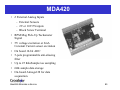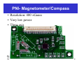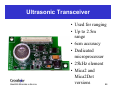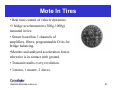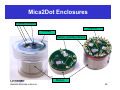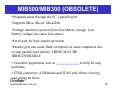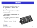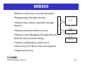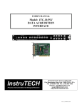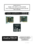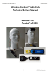
1
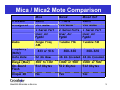
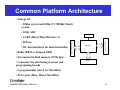
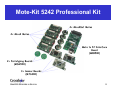
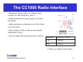
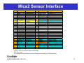
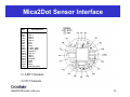
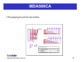
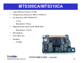
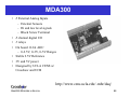
Mote Hardware Session
Overview:
•Platforms & Interfaces
•Sensor Boards and Design
•Programming Boards
•Gateways
SMARTER SENSORS IN SILICON
1
Family of Motes
SMARTER SENSORS IN SILICON
2
Mica / Mica2 Mote Comparison
Processor
Atmega128
Radio
Frequency
(MHz)
Data Rate
Range (Max)
On-Board
Flash
Unique ID
Mica
4MHz
103 Mode
1 Serial Port
Over Air
Pgmbl
Single Freq
AM
433 or 916
433 or 916
Mica2
7.7MHz
128 Mode
2 Serial Ports
Over Air
Pgmbl
Tunable FM
Mica2 Dot
4MHz
128 Mode
1 Serial Port
Over Air
Pgmbl
Tunable FM
52 Kb Raw
432-434 or
432-434 or
300-320
300-320
902-928
902-928
38 Kb Encoded 38 Kb Encoded
300’ to 100’
512 Kbytes
1000’ or 500’
512 Kbytes
1000’ or 500’
512 Kbytes
No
Yes
Yes
SMARTER SENSORS IN SILICON
3
Common Platform Architecture
• Atmega uP
• 32Khz crystal and 4Mhz (7.3728Mhz Mica2)
crystal.
• 10 bit ADC
LEDS
• UART (Mica2/Mica2Dot have 2)
• Radio (RFM or Chipcon 1000)
Atmega uP
SERIAL FLASH
• I2C bus (hardware for mica2/mica2dot)
51 PIN I/O CONNECTOR
• SPI bus
• External serial flash memory (512K byte)
• Connectors for interfacing to sensor and
programming boards
RADIO
• 3 programmable leds (1 for Mica2Dot)
• JTAG port (Mica, Mica2, Mica2Dot)
SMARTER SENSORS IN SILICON
4
Mote-Kit 5242 Professional Kit
4× Mica2Dot Motes
4× Mica2 Motes
Mote to PC Interface
Board
(MIB500)
2× Prototyping Boards
(MDA500)
3× Sensor Boards
(MTS300)
SMARTER SENSORS IN SILICON
5
The CC1000 Radio Interface
• Dedicated cpu bus (lines) to configure radio
registers for radio frequency, power,…..
• Dedicated SPI bus for data transfer. CC1000 is
bus master.
• Radio generates one interrupt every 8 bits when
in receive mode.
• Runs usually at 38K or 19K bit rate (default)
Manchester (2x bit)
• More in-depth radio discussion later in session.
Baud Rate
Xmt or Rcv Time(*)
19K
~40msec
38K
~20msec
(*) Does not include random delay
SMARTER SENSORS IN SILICON
6
The Flash Memory Interface
• 512 K bytes of flash (non-volatile) storage
• Useful for data logging.
• Used by GSK (Generic Sensor Kit) and TinyDB for data
logging.
• Used by XNP for code download.
• Serial interface to Atmega uP
• TinyOS driver (Logger..) bit bangs interface
• Attached to 2nd uart port on Mica2. Another driver (UCB)
uses synchonous usart for high speed data transfer.(5KB/Sec
driver)
•Beware, device consumes 15 ma when storing to memory
SMARTER SENSORS IN SILICON
7
The ADC Interface
• Eight channels of 10 bit ADC, multiplexed.
• Dedicated channels (Mica2):
• ADC0 : Radio’s RSSI
• Shared Mica2 Channels
• ADC7 : Battery monitor (can be shared with another
channel but will have ~10K ohm impedance.
• ADC4..ADC7: JTAG. If using JTAG debug these
channels won’t work as ADC inputs.
• Shared Mica2Dot Channels
• ADC1: Shared for both thermistor and battery voltage
• ADC4..ADC7: JTAG. If using JTAG debug these
channels won’t work as ADC inputs
SMARTER SENSORS IN SILICON
8
Mica2 Sensor Interface
Pin
1
2
3
4
5
6
7
Name
GND
VSNR
INT3
INT2
INT1
INT0
BAT_MON
8
9
10
11
12
13
14
15
16
17
18
19
20
21
22
23
24
25
26
LED3
LED2
LED1
RD
WR
ALE
PW7
USART1_CLK
PROG_MOSI
PROG_MISO
SPI_CLK
USART1_RXD
USART1_TXD
I2C_CLK
I2C_DATA
PWMO
PWM1A
AC+
AC-
Description
Ground
Voltage(battery)
GPIO
GPIO
GPIO
GPIO
Battery Monitor
Voltage
Green Led
Yellow Led
Red Led
GPIO
GPIO
GPIO
GPIO
Usart clock
Programmer Pin
Programmer Pin
Radio Clock
Usart1 receive
Usart1 xmit
I2C bus clock
I2C bus data
GPIO
GPIO
GPIO
GPIO
Pin
27
28
29
30
31
32
33
Name
UART_RXDO
UART_TXDO
PWO
PW1
PW2
PW3
PW4
Description
Uart0 Rcv
Uart0 Tx
GPIO/PWM
GPIO/PWM
GPIO/PWM
GPIO/PWM
GPIO/PWM
34
35
36
37
38
39
40
41
42
43
44
45
46
47
48
49
50
51
PW5
PW6
ADC7
ADC6
ADC5
ADC4
ADC3
ADC2
ADC1
ADC0
THERM_PWR
THRU1
THRU2
THRU3
RSTN
PWM1B
VCC
GND
GPIO/PWM
GPIO/PWM
GPIO/ADC CH7, JTAG
GPIO/ADC CH6, JTAG
GPIO/ADC CH5, JTAG
GPIO/ADC CH, JTAG
GPIO/ADC CH3
GPIO/ADC CH2
GPIO/ADC CH1
GPIO/ADC CH0
GPIO
Thru user connect
Thru user connect
Thru user connect
uP reset
GPIO
Voltage (battery)
ground
Blue: OK to use
Yellow: OK to use but has shared functionality
Red: Do no use
See Atmega128 specification for more information regarding signal functionality.
SMARTER SENSORS IN SILICON
9
Mica2 Sensor Interface
SMARTER SENSORS IN SILICON
10
Mica2Dot Sensor Interface
P IN
TP1
TP2
TP3
TP4
TP5
TP6
TP7
TP8
TP9
T P10
T P11
T P12
T P13
T P14
T P15
T P18
T P19
T P20
T P21
D E S C R IP T IO N
GND
ADC7
ADC6
ADC5
ADC4
VCC
PW 1
PW 0
U AR T_TX D
U AR T_R X D
RESETN
S P I_ C K
ADC3
ADC2
PW M 1B
GND
IN T 1
IN T 0
T H ER M _PW R
• 6 ADC Channels
• 6 I/O Channels
SMARTER SENSORS IN SILICON
11
Battery Life Computation
• Two models:
•1% duty cycle
•0.5% duty cycle
• Conclusion:
• To achieve multiyear battery life, must
sleep most of the time.
SYSTEM SPECIFICATIONS
Currents
Duty Cycles
Model 1
Model 2
value
units
Micro Processor (Atmega128L)
current (full operation)
6 ma
current sleep
8 ua
Radio (Chipconn 1000)
current in receive
8 ma
current xmit
12 ma
current sleep
2 ua
Flash Serial Memory (AT45DB041)
write
15 ma
read
4 ma
sleep
2 ua
Sensor Board
current (full operation)
5 ma
current sleep
5 ua
Battery Specifcations
3%
Capacity Loss/Yr
L if e
T im e
v s
units
1
99
0.5 %
99.5 %
0.75
0.25
99
0.4 %
0.1 %
99.5 %
0
0
100
0%
0%
100 %
1
99
0.5 %
99.5 %
B a t t e r y C a p a c it y
3 5 .0 0
• Spread Sheet in on CD
3 0 .0 0
Battery Life (months)
2 5 .0 0
2 0 .0 0
M o d e l 1
M o d e l 2
1 5 .0 0
1 0 .0 0
5 .0 0
0 .0 0
SMARTER SENSORS IN SILICON
0
1 0 0 0
2 0 0 0
B a tte r y
C a p a c it y
3 0 0 0
(m
a -h r )
4 0 0 0
12
MICAz (Coming Soon)
• Chipcon CC2420, 802.15.4, Zigbee Radio
• Same platform (Atmega128,flash…) as MICA2
•2.4 Ghz (same as Wi-Fi and Bluetooth)
• Direct Spread Spectrum
• 250 kps throughput
• Range:
• Indoors 60’ (~80% of 916 Mhz mica2)
• Outdoors 150’ (~50% of 916Mhz mica2)
• Hardware MAC encryption
• 128 byte Rx/Tx fifo
• FCC certified
SMARTER SENSORS IN SILICON
13
MICA3 (Coming Soon)
• Chipcon CC1020 Radio
• Same platform (Atmega128,flash…) as MICA2
• 433Mhz and 916 Mhz bands
• GFSK
• 76 kps throughput
• 27dbm output for extended range
• FCC certified
SMARTER SENSORS IN SILICON
14
Next Generation Atmega (2004)
• 0.1 uA power down (10uA for ATmega128)
• 1.8 volt operation ( 2.4 for ATmega128)
• Atmega256: 256K flash, 8K ram
SMARTER SENSORS IN SILICON
15
Crossbow Sensor Boards
Part #
Mote Support
Sensors
MTS101CA
MICA,MICA2
Light (photo resistor)
Temperature (Thermistor)
Prototyping area
MDA300CA
MICA2DOT
Protoyping
MTS300CA
MICA, MICA2
Light, Temperature, Acoustic, Sounder, 2Axis Accelerometer (ADXL202), and 2-Axis
Magnetometer
MTS500CA
Mica2Dot
Prototyping
MDA300CA
Mica2
On board humidity/temp. External sensors.
MTS400/420
Mica2
GPS weatherboard
MDA420
Mica2
High speed vibration
See MTS/MDA Sensor and Data Acquisition Boards User’s Manual
SMARTER SENSORS IN SILICON
16
MTS101CA
•Light photo resistor-Clairex CL94L
• Thermistor - YSI 44006,
•Both sensor are highly non-linear.
•Good prototyping area.
To use this sensor board add (modify) the
apps/app/makefile for:
SENSORBOARD = basicsb
a b c d e
U 1
1
2 6
5 1
PW1
RT1
Thermistor
R2
Photoresistor
ADC5
R3
10K, 5%
gnd_analog
1
2
3
4
5
6
7
8
9
1 0
1 1
1 2
2 7
PW2
ADC6
R1
10K, 5%
gnd_analog
T h e r m is t o r ( R T 1 )
L ig h t S e n s o r ( R 2 )
a b c d e
SMARTER SENSORS IN SILICON
17
MDA500CA
• Prototyping board for mica2dots
SMARTER SENSORS IN SILICON
18
MTS300CA/MTS310CA
•
•
•
•
•
•
•
Light (Photo)-Clairex CL94L
Temperature-Panasonic ERT-J1VR103J
Acceleration-ADI ADXL202
– 2 axis
– Resolution: ±2mg
Magnetometer-Honeywell HMC1002
– Resolution: 134µG
Microphone
Tone Detector
Sounder
– 4.5kHz
SMARTER SENSORS IN SILICON
SENSORBOARD = micasb
19
MTS400/420 – GPS/Weather
• Gps (LeadTek 9546) - optional
• SiRFstartII LP chipset (60ma)
• External active antenna.
• 12 channels
• 15 Meter ( SA off); 7 Meter (WAAS
corrected)
• DC Booster to maintain required
voltage
•Temperature & Humidity (Sensirion
SHT11).
• All digital (14 bits)
• 3.5% RH accuracy, 0.5degC
Temperature accuracy
SMARTER SENSORS IN SILICON
20
MTS400/420 – GPS/Weather
•Barometric Pressure and Temperature
(Intersema MS5534A)
• All digital
• 300 to1100 mbar, 3% accuracy
• -10 to +60 degC, 3% accuracy
• Ambient Light (TAOS TSL2250)
•All digital
•400-1000nm response
•Acceleration-ADI ADXL202
–2 axis
–Resolution: ±2mg
•2 K EEPROM for user configuration info.
SMARTER SENSORS IN SILICON
21
MDA300
•
•
•
•
•
•
•
8 External Analog Inputs
– External Sensors
– Hi and low level signals
– Block Screw Terminal
8 channel digital I/O
2 relays
On board 12-bit ADC
– 0-2.5V, 0-3V, 0-5V Ranges
Stable 2.5V Reference
3V and 5V power
Designed by UCLA CENS w/
Crossbow and UCB
http://www.cens.ucla.edu/~mhr/daq/
SMARTER SENSORS IN SILICON
22
MDA420
•
•
•
•
•
•
•
•
6 External Analog Inputs
– External Sensors
– 2V or 10V FS inputs
– Block Screw Terminal
RPM Mag Pick-Up Tachometer
Signal
5V voltage excitation or 2mA
Constant Current sensor excitation
On board 16-bit ADC
5-pole programmable anti-aliasing
filter
Up to 25 KiloSample/sec sampling
64K sample data storage
On-board Atmega128 for data
acquisition.
SMARTER SENSORS IN SILICON
23
PNI- Magnetometer/Compass
• Resolution: 400 µGauss
• Very low power
• Three axis
SMARTER SENSORS IN SILICON
24
Ultrasonic Transceiver
SMARTER SENSORS IN SILICON
• Used for ranging
• Up to 2.5m
range
• 6cm accuracy
• Dedicated
microprocessor
• 25kHz element
• Mica2 and
Mica2Dot
versions
25
Mica2Dot Weather Board
• UCB environmentally packaged weatherboards for GDI
•Temperature & Humidity (Sensirion SHT11).
• All digital (14 bits)
• 3.5% RH accuracy, 0.5degC Temperature accuracy
•Barometric Pressure and Temperature (Intersema MS5534A)
• All digital
• 300 to1100 mbar, 3% accuracy
• -10 to +60 degC, 3% accuracy
•Ambient Light (TAOS TSL2250)
•All digital
•400-1000nm response
• Photosensitive Light Sensor..
SMARTER SENSORS IN SILICON
26
Mote In Tires
• Real time control of vehicle dynamics.
•3 bridge accelerometers (500g-1000g)
mounted in tire.
• Sensor board has 3 channels of
amplifiers, filters, programmable D/As for
bridge balancing.
•Monitor and analyzed acceleration forces
when tire is in contact with ground.
• Transmit results every revolution.
• 3 motes, 1 master, 2 slaves.
SMARTER SENSORS IN SILICON
27
Micro Radar
•Darpa project: Detect intruders with micro-powered
radar detectors and relay data through mote network.
•Drop detectors from UAV (ex: Predator)
•Ghz Doppler radar detector.
• Done with LLL and Advantaca
SMARTER SENSORS IN SILICON
28
COTS-BOTS (UCB)
• 5” x 2.5” x 3” size
• <$250 total
• 2-axis accelerometer
SMARTER SENSORS IN SILICON
29
MICAbot (Notre Dame)
•
•
SMARTER SENSORS IN SILICON
Designed for large-scale research in
distributed robotics and ad-hoc wireless
networking.
$300 each
30
Building Apps with Different Sensor
Boards
Select different sensor boards by
editing the /apps/../makefile:
SENSORBOARD=micawbdot
SMARTER SENSORS IN SILICON
31
Ratiometric Adcs & Sensors
• Atmega128 is 10 bit (1024) ratio metric ADC
• If sensor is ratio metric then don’t have to
measure battery voltage. (Sensor’s FS changes
with battery voltage).
•Ratio metric sensors may not work over full range
of battery voltage, be careful.
•ADC full scale is proportional to battery voltage.
• Must measure battery voltage to get accurate
sensor readings:
ADC Output vs Battery
Voltage for 1.5V input
700
680
660
640
620
600
580
560
540
520
500
2
2.5
3
3.5
Battery Volts = RefVolt*ADC_FS/data
•Mica2 and Mica2Dot have on-board voltage
references to calibrate the ADC full scale.
/contrib/xbow/apps/XSensorMica2
SMARTER SENSORS IN SILICON
32
Other Adcs & Sensors
• MTS420 (gps wb) and mica2dot weatherboards use sensors with built in
ADCs.
• This improves accuracy but at a higher sensor cost (3x-5x cost increase)
• MDA300 uses on-board precision 12 bit ADC with a good voltage
reference. Shared with all 8 input channels. Good, cost effective solution
SMARTER SENSORS IN SILICON
33
Enclosures for Environmental
Monitoring
SMARTER SENSORS IN SILICON
34
Mica2Dot Enclosures
Weather Sensors
On/Off
O-Ring
Battery Interface Board
Battery
SMARTER SENSORS IN SILICON
35
Sensor Power Management
• Simple Strategy for Low Power Sensors:
• Use Atmega output pins to source sensor power.
PW2
RT1
Thermistor
• Will source ~5-10ma of current per pin.
ADC5
R3
10K, 5%
• Analog Switch Strategy
gnd_analog
• Use hardware I2C (mica2) or software I2C (mica2dot)
(in Sourceforge)
• Switch connects sensor power to VCC.
VCC
Power
Switches
• ADG714 switch has 2.5 ohm on resistance
U7
• Create battery independent, constant supply voltage.
• Create +5 V or more
I2C_BUS_1_DATA
I2C_BUS_1_CLK
I2C_BUS_1_DATA
I2C_BUS_1_CLK
ADG715BRU
19
D8 17
D7 15
D6 13
D5 12
D4 10
D3 8
D2 6
D1
3
1 SDA
SCLK
23
24 RST
22 A0
A1
5V_DC-DC_Shutdown
3.3V_DC-DC_Shutdown
Accel_Power
EEPROM_Power
Humidity_Power
Pressure_Power
Light_Power
R11 R9
1M 1M
R10 R13
1M 1M
R12
1M
21
4
• Turn on booster from analog switch or Atmega
VCC
Accel_Out
S8
S7
S6
S5
S4
S3
S2
S1
VSS
GND
• DC-DC Booster Strategy
20
18
16
14
11
9
7
5
2
R19 R17
1M 1M
• Boosters are ~80%-90% efficient. Need good layout and
decoupling. Not ratiometric
SMARTER SENSORS IN SILICON
36
Mote Programming and Base Station
Boards
Overview:
• MIB500/MIB300 Parallel Port Programmer
• MIB510 Serial Port Programmer
• MIB600 LAN Programmer
SMARTER SENSORS IN SILICON
37
MIB500/MIB300 (OBSOLETE)
•Programs mote through the PC’s parallel port
•Supports Mica, Mica2, Mica2Dot
•Voltage monitor to protect from low battery voltage. Low
battery voltage can cause fuse errors.
•Serial port for base station operation
•Parallel port can cause flash corruption on some computers due
to uisp parallel port drivers. THESE MAY BE
IRRECOVERABLE
• Crossbow application note at www.xbow.com to help fix uisp
problems.
• JTAG connector: AVRStudio and JTAG pod allows viewing
and setting all fuses.
SMARTER SENSORS IN SILICON
38
MIB510
•Programming through the serial port.
On board ISP uP is 3x faster than
parallel port.
•Shares serial port with mote for base
station operation.
•Voltage monitor to protect from low
battery voltage
• Suports Mica (Atmega128 uP only),
Mica2, Mica2Dot
• JTAG port powered directly.
SMARTER SENSORS IN SILICON
39
MIB600
•Ethernet connection as serial forwarder.
•Programming through ethernet.
ISP uP
• Remote powered ethernet sensor.
• Remote code debugging through ethernet.
Ideal for mote network debug.
Ethernet
• Remote base station operation through
ethernet.
Serial
Serial
MOTE
SENSOR BOARD
• Similar configuration (eprb) used
extensively at UCB for mote development.
• Supported in uisp
SMARTER SENSORS IN SILICON
40