1
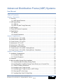
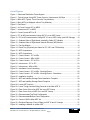
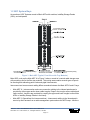
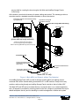
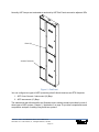
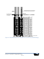
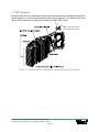
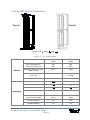
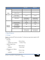
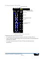
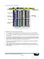
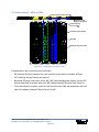
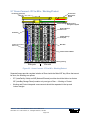
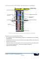
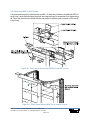
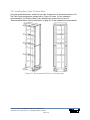
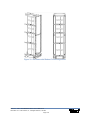
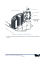
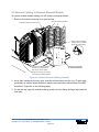
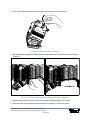
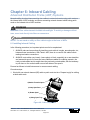
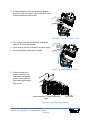
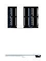
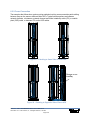
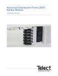
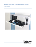
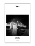
Advanced Distribution Frame (ADF) Systems
User Manual
Advanced Distribution Frame (ADF) Systems
User Manual 119736-4 A0
Copyright 2010, Telect, Inc., All Rights Reserved
Telect and Connecting the Future are registered trademarks of Telect, Inc.
1730 N Madson St., Liberty Lake, Washington
Telect assumes no liability from the application or use of these products. Neither does Telect convey any
license under its patent rights nor the patent rights of others. This document and the products described
herein are subject to change without notice.
About Telect
Telect offers complete solutions for physical layer connectivity, power, equipment housing and other
network infrastructure equipment. From outside plant and central office to inside the home, Telect draws on
more than 25 years of experience to deliver leading edge product and service solutions. Telect is
committed to providing superior customer service and is capable of meeting the dynamic demands of
customer and industry requirements. This commitment to customer and industry excellence has positioned
Telect as a leading connectivity and power solution provider for the global communications industry.
Technical Support
E-mail: [email protected]
Phone: 888-821-4856 or 509-921-6161
Telect, Inc. • USA +1.509.926.6000 • Mexico +52.33.3836.37.52
www.telect.com • © 2010 Telect, Inc., All Rights Reserved, 117736-4 A0
Page ii
Advanced Distribution Frame (ADF) Systems
User Manual
Table of Contents
Chapter 1: Description .............................................................................................................. 1
1.1 Overview .......................................................................................................................... 1
1.1.1 ADF System Features ............................................................................................. 3
1.2 ADF System Bays ............................................................................................................ 4
1.2.1 ADF XIs ................................................................................................................... 7
1.2.2 ADF ICs (after Trough Removed) ........................................................................... 9
1.3 ADF Modules ................................................................................................................. 11
1.4 Telect ADF Feature Comparison ................................................................................... 14
1.5 Specifications ................................................................................................................. 16
1.5.1 Weight ................................................................................................................... 16
1.5.2 Overall Dimensions ............................................................................................... 17
Chapter 2: Applications ........................................................................................................... 19
2.1 Cross-Connect - IFC to NEs .......................................................................................... 19
2.2 Cross-Connect - NEs to NEs ......................................................................................... 20
2.3 Cross-Connect - IFC to IFCs ......................................................................................... 21
2.4 Interconnect - IFC to IFC ............................................................................................... 22
2.5 Interconnect - NEs to NEs ............................................................................................. 23
2.6 Interframe Cross-Connecting ......................................................................................... 24
2.7 Cross-Connect - IFC to NEs - Working/Protect ............................................................. 25
2.8 Cross-Connect - IFC to NEs - Working/Protect - Standalone ........................................ 26
Chapter 3: Frame Installation ................................................................................................. 27
3.1 Installation Considerations ............................................................................................. 27
3.1.1 Location & Space .................................................................................................. 27
3.1.2 Tools & Equipment ................................................................................................ 27
3.2 Inspection ....................................................................................................................... 28
3.3 Main & InterBay Storage Panel Installation ................................................................... 28
3.3.1 Unpacking Main & InterBay Storage Panels ......................................................... 28
3.3.2 Installing Main & InterBay Storage Panels Directly on a Concrete Floor .............. 29
3.3.3 Table of Footprint Dimensions .............................................................................. 31
3.3.4 Installing Lower Trough Junction .......................................................................... 32
3.3.5 Installing Upper Trough Junction on ADF XI Bays ................................................ 32
3.3.6 Securing ADF to the Lineup .................................................................................. 33
3.3.7 Installing Rear Cable Tie-Down Bars .................................................................... 34
Telect, Inc. • USA +1.509.926.6000 • Mexico +52.33.3836.37.52
www.telect.com • © 2010 Telect, Inc., All Rights Reserved, 119736-4
Page iii
3.3.8 Installing Cable Management System (CMS) ....................................................... 36
3.3.9 Grounding ADF ..................................................................................................... 36
3.3.10 Securing ADF Lineup .......................................................................................... 36
3.3.11 Wiring Facility Power ........................................................................................... 36
Chapter 4: Module Installation ................................................................................................ 39
4.1 Installation Considerations ............................................................................................. 39
4.1.1 Pre-Cabled Vs. Uncabled ADF Modules ............................................................... 39
4.1.2 Tools & Equipment Required ................................................................................ 39
4.2 Inspection ....................................................................................................................... 39
4.3 Unpacking an ADF Module ............................................................................................ 39
4.4 Installing an ADF Module to a Main ADF ....................................................................... 40
Chapter 5: Outboard Cabling .................................................................................................. 43
5.1 Intrafacility Cable to Uncabled IFC Module .................................................................... 43
5.2 Network Cabling to Network Element Module ............................................................... 47
Chapter 6: Inboard Cabling ..................................................................................................... 51
6.1 Installing Inboard Cabling .............................................................................................. 51
6.2 Routing & Storing Inboard Cabling ................................................................................ 54
6.2.1 Interconnection ...................................................................................................... 54
6.2.2 Cross-Connection ................................................................................................. 56
Chapter 7: Service ................................................................................................................... 59
7.1 Owner Maintenance ....................................................................................................... 59
7.2 Technical Support .......................................................................................................... 59
7.3 In-Warranty Service ....................................................................................................... 59
7.4 Out-of-Warranty Service ................................................................................................ 59
7.5 Repacking for Shipment ................................................................................................. 59
Chapter 8: Bays and Accessories .......................................................................................... 61
Telect, Inc. • USA +1.509.926.6000 • Mexico +52.33.3836.37.52
www.telect.com • © 2010 Telect, Inc., All Rights Reserved, 119736-4
Page iv
List of Figures
Figure 1 - Advanced Distribution Frame System ......................................................................... 1
Figure 2 - Typical Lineup Using ADF Cross-Connect / Interconnect (XI) Bays ........................... 2
Figure 3 - Main ADF (Typical, Front View with Tray Modules) .................................................... 4
Figure 4 - Main ADFs (as Shipped, without Tray Modules) ......................................................... 5
Figure 5 - End Panel .................................................................................................................... 6
Figure 6 - XI Cross-Connect IFC to NE22 ................................................................................... 7
Figure 7 - Interconnect IFC to NE33 ............................................................................................ 8
Figure 8 - Cross-Connect NFC to IE ............................................................................................ 8
Figure 9 - IFC to NE Interconnection Using ADF ICs in an ADF Lineup ...................................... 9
Figure 10 - IFC to NE Interconnection Using ADF ICs in an ADF LIneup (with ISP Storage) ... 10
Figure 11 - Outboard View of Right-Hand, Intrafacility Cable (IFC) Module .............................. 11
Figure 12 - Outboard View of Right-Hand, Network Element (NE) Module ............................... 12
Figure 13 - Fan-Out Module ....................................................................................................... 12
Figure 14 - Patch Tray (Physically the Same for IFC, NE, and FO Modules) ............................ 13
Figure 15 - ADF Comparisons ................................................................................................... 14
Figure 16 - ADF Comparisons ................................................................................................... 15
Figure 17 - Cross-Connect - IFC to NEs .................................................................................... 19
Figure 18 - Cross-Connect - NEs to NEs ................................................................................... 20
Figure 19 - Cross-Connect - IFC to IFCs ................................................................................... 21
Figure 20 - Interconnect - IFC to IFC ......................................................................................... 22
Figure 21 - Interconnect - NEs to NEs ....................................................................................... 23
Figure 22 - Interframe Cross-Connecting ................................................................................... 24
Figure 23 - Cross-Connect - IFC to NEs - Working/Protect ....................................................... 25
Figure 24 - Cross-Connect - IFC to NEs - Working/Protect - Standalone .................................. 26
Figure 25 - Installation Location ................................................................................................. 27
Figure 26 - ADF and InterBay Storage Panel Installation Template .......................................... 29
Figure 27 - ADF and InterBay Storage Panel Footprints ........................................................... 30
Figure 28 - Lower ADF Junction ................................................................................................ 32
Figure 29 - Lower Trough Junction Being Secured to the Main ADF XI .................................... 32
Figure 30 - Rear Corner View of an ADF XIs in an ADF Lineup ................................................ 33
Figure 31 - Rear Corner View of ADF ICs in an ADF Lineup ..................................................... 33
Figure 32 - Recommended Top Feed Configuration ................................................................. 34
Figure 33 - Recommended Bottom Feed Configuration ............................................................ 35
Figure 34 - Connect CMS to Main ADF XIs ............................................................................... 36
Figure 35 - Electrical Raceway (Front of Base) on ADF XI and IC Lineups .............................. 37
Figure 36 - Installing a Module on a Main ADF .......................................................................... 41
Telect, Inc. • USA +1.509.926.6000 • Mexico +52.33.3836.37.52
www.telect.com • © 2010 Telect, Inc., All Rights Reserved, 119736-4
Page v
Figure 37 - Adjusting Latch Bars (ADF Module Not Shown) ...................................................... 42
Figure 38 - Intrafacility Clamp and Cable ................................................................................... 43
Figure 39 - Riser Cabling to Uncabled IFC Module ................................................................... 44
Figure 40 - Securing Connector to Adapter ............................................................................... 45
Figure 41 - Routing Cable to Breakout Area .............................................................................. 45
Figure 42 - Excess Cable Routing ............................................................................................. 46
Figure 43 - Network Element Cabling (Example) ....................................................................... 47
Figure 44 - Opening Trays ......................................................................................................... 48
Figure 45 - Securing Connector to Adapter ............................................................................... 48
Figure 46 - Routing Cable to Channel ....................................................................................... 49
Figure 47 - Cable Routing through Channel to Rear of Module ................................................. 49
Figure 48 - Cable Preparation .................................................................................................... 51
Figure 49 - Connecting Patch Cord ........................................................................................... 52
Figure 50 - Cable Routing in Tray .............................................................................................. 52
Figure 51 - Cable Routing in Module ......................................................................................... 52
Figure 52 - Interconnecting Cable Routing ................................................................................ 53
Figure 53 - Cross-Connecting Cable Routing ............................................................................ 53
Figure 54 - Cable Routing Down Cascade ................................................................................ 53
Figure 55 - Interconnection within a Single Frame .................................................................... 54
Figure 56 - Interconnection with Storage on ISP ....................................................................... 55
Figure 57 - Patching to Same Side of Same ADF ..................................................................... 56
Figure 58 - Patching to Opposite Side of Same ADF ................................................................ 56
Figure 59 - Patching to Same Side of Different ADFs ............................................................... 57
Figure 60 - Patching to Opposite Side of Different ADFs (without ISP) ..................................... 57
Figure 61 - Patching to Opposite Side of Different ADFs (with ISP) .......................................... 58
Telect, Inc. • USA +1.509.926.6000 • Mexico +52.33.3836.37.52
www.telect.com • © 2010 Telect, Inc., All Rights Reserved, 119736-4
Page vi
Chapter 1: Description
Advanced Distribution Frame (ADF) Systems
1.1 Overview
Telect’s ADF Systems provide inter-connectivity and cross-connectivity of intrafacility cables,
network elements, and patch cords.
•
Each Main ADF consists of an upright frame holding a vertical array of modules on each side
of a patch cord interconnect routing area.
•
Each module holds trays for interconnections or cross-connections.
Each swing-out tray supports 6, 8, or 12 optical connections, depending on the type of adapter.
V e rtic al Spo o l Array fo r
R ou tin g P a tch Ca bling
Be tw ee n M od u les
Upper Trough
T ra ys H o ld 6, 8, or 12 O ptical Ad ap te rs
M od ules W ith Tra ys
ADF Types & Versions
The Telect ADF-XI comes as pictured.
The trough can be removed to provide
inter-connectivity. [ADF-IC]
Two versions of ADF XI are offered,
an ETSI versions and a North American
version. The ETSI version is shown here.
L ow er T roug h
Covers Protect Cable in Bottom Troughs
ADF-12INT-XI
ADF-26F-XI
Figure 1 - Advanced Distribution Frame System
•
ADFs with 12 adapters per tray have up to 2304 junctions per bay (LC).
•
ADFs with 8 adapters per tray have up to 1536 junctions per bay.
•
ADFs with 6 adapters per tray have up to 1152 junctions per bay.
Telect, Inc. • USA +1.509.926.6000 • Mexico +52.33.3836.37.52
www.telect.com • © 2010 Telect, Inc., All Rights Reserved, 119736-4
Page 1-1
Figure 1, “Advanced Distribution Frame System” on page 1, depicts a multipurpose ADF XI bay
with a complete array of modules and an ADF InterBay Storage panel.
The area between right-side and left-side modules contains various spools for routing patch
cords and/or pigtail interconnects. Bulk patch cord storage is provided by InterBay Storage
Panels (ISPs) located between Main ADFs in ADF System lineups.
N o rm a lly , th e to p tra y o f ea c h
q ua d ra n t is c o v e re d t o p ro te c t cab le s
a nd ad a p te rs fro m o v e rhe a d ha za rd s.
Cable
Figure 2 - Typical Lineup Using ADF Cross-Connect / Interconnect (XI) Bays
ADF system lineups consist of Main ADFs, ISPs, and end panels.
Cable, patch cord, and pigtail access differs somewhat between Telect’s ADF Cross-Connect /
Interconnect (XI) and Interconnect (IC) Systems, but generally IFC, OSP, or network element
Telect, Inc. • USA +1.509.926.6000 • Mexico +52.33.3836.37.52
www.telect.com • © 2010 Telect, Inc., All Rights Reserved, 119736-4
Page 1-2
(NE) access are connected at the rear of the modules. Patch cords, as well as NE pigtail
interconnects, are connected at the front of the modules. In cross-connect applications, patch
cords are routed between modules on different Main ADFs through upper and/or lower ADF
troughs.
1.1.1 ADF System Features
•
Industry-leading termination density
•
Simple, straight-forward cable management, access, circuit identification and isolation
•
No fishing of cables
•
Total front access for patching
•
Designed for compliance (fiber bend radius control, flammability safety, structural reliability)
throughout ADF design
•
No line-of-sight laser hazards
•
Easy access to riser/network/patch cord interconnections and cross-connections
•
Light-weight, heavy-duty frame certified for Zone 4 earthquake reliability
•
Easy installation
•
600-mm and 26-in. rack widths that accommodate standard lineups
•
Diverse routing with reduced cable congestion. Diverse routing between ADFs using upper
and/or lower troughs.
•
4.5-m standard, single-length patch cords for ADF cross connections
•
Unique storage spools with wave-like ridges for grouping patch cords
•
Variable placement of tray modules on ADF mounting rails
•
Compatible with WaveTrax™ Cable Management System and other cable
management systems
Telect, Inc. • USA +1.509.926.6000 • Mexico +52.33.3836.37.52
www.telect.com • © 2010 Telect, Inc., All Rights Reserved, 119736-4
Page 1-3
1.2 ADF System Bays
As mentioned, ADF Systems consist of Main ADFs with modules, InterBay Storage Panels
(ISPs), and end panels.
Intrafacility Cabling
Intrafacility Cabling
Figure 3 - Main ADF (Typical, Front View with Tray Modules)
Main ADFs, such as the Main ADF XI in Figure 3, above, consist of a central cable storage area
with mounting rails for the fiber tray modules. The routing area contains several types of spools
for directing and redirecting patch cords and pigtail interconnects.
Interconnect and cross-connect cabling differs somewhat between the Main ADF XI and IC bays:
•
Main ADF XI - Interconnection and cross-connection cabling to the inboard patch areas is
provided by either upper and/or lower cable troughs. Drops in the troughs ensure cable bend
radius control. Junctions are provided for coupling the upper and lower troughs to other Main
ADFs or InterBay Storage Panels in the lineup.
•
Main ADF IC (Specialized for Interconnections) - Interconnect cabling to the inboard patch
area is by direct access from a cable management system above the ADF lineup. Junctions
Telect, Inc. • USA +1.509.926.6000 • Mexico +52.33.3836.37.52
www.telect.com • © 2010 Telect, Inc., All Rights Reserved, 119736-4
Page 1-4
are provided for coupling the lower troughs of all Main and InterBay Storage Panels
in the lineup.
At the bottom is an electrical raceway for power cabling and conduit. The raceway provides a
mounting area for a standard recessed receptacle or other wiring device.
Small holes are tappedto connect dual-hole grounding
lug using M5 screws
Large holes for securing ADF
to the CMS or a ladder rack
Upper ADF Trough (Main ADF XI Only)
Catch for Tray Latch
Main ADF
Interconnect
Main
ADF IC (IC)
without
top trough)
(shown(shown
with top
trough
removed)
Junction (not shown) fits on the edge to
connect the upper trough to the adjacent
frame in the lineup (Main ADF XI [cross-connect] only)
Lower ADF Trough
Patch Cord Cascade
With Turnstiles
Coupling (not shown) fits on lip to
connect lower trough to adjacent
frame in lineup
Cover Plate for Standard Electrical
Receptacle
31.8 mm/1.25 in. (Diameter) Access Hole
on Both Ends of Raceway
MainADF
ADFXI
XIonly
Main
Figure 4 - Main ADFs (as Shipped, without Tray Modules)
An InterBay Storage Panel (ISP) is used for storage of either patch cord cabling from an
overhead CMS and/or inboard cabling terminated at IFC or NE modules. Except for the tray
modules, cable routing through an InterBay Storage Panel is similar to that of a Main ADF.
The Main ADF and ISP can be mounted directly to a concrete floor or on a raised equipment
floor. (A template is provided for mounting panels to the floor.) Support is provided at the top for
added earthquake security and for attaching to a cable management or ladder rack system.
Telect, Inc. • USA +1.509.926.6000 • Mexico +52.33.3836.37.52
www.telect.com • © 2010 Telect, Inc., All Rights Reserved, 119736-4
Page 1-5
Normally, ADF lineups are terminated at each end by ADF End Panels secured to adjacent ISPs.
Doors (2)
Access Covers (2)
Figure 5 - End Panel
You can configure two types of ADF System bays that fit North American and ETSI footprints:
1. ADF Cross-Connect / Interconnect (XI) Bays
2. ADF Interconnect (IC) Bays
The subsections that follow describe and illustrate various cabling scenarios provided by each of
these types of ADF systems. Chapter 2, “Applications” on page 19, provides comprehensive and
comparative analyses of cabling using these two systems.
Telect, Inc. • USA +1.509.926.6000 • Mexico +52.33.3836.37.52
www.telect.com • © 2010 Telect, Inc., All Rights Reserved, 119736-4
Page 1-6
1.2.1 ADF XIs
ADF Cross-Connect/Interconnect bays are used in either cross-connect or interconnect
applications, depending on the type of module installed on the Main ADFs. Lineup access to the
patch cord area on the Main ADFs is through either the bottom or upper troughs with access to/
from patch cord storage on the ISPs via the bottom trough.
Two models are available:
1. The North American model is based on a 26 in. by 24 in. Main ADF footprint. ISPs for the
North American model are 12 in. by 24 in.
2. The ETSI model is based on a 600 mm by 600 mm Main ADF footprint. ISPs for the ETSI
model are 300 mm by 600 mm.
The following figures show a few typical cross-connection and interconnection schemes between
IFC and network element (NE) cabling. In these examples, IFC routing to the rear of the IFC ADF
modules is from the facilities cable (ladder) rack with NE cabling through a cable management
system (CMS).
IFC Cabling to Rear
(Outboard Side)
of IFC Module
Ladder Rack
CMS
Preferred Pigtail
Route from Outboard
Side of NE Module
Via CMS to Network
Element
Patch Cord
Alternate Route
Figure 6 - XI Cross-Connect IFC to NE22
Telect, Inc. • USA +1.509.926.6000 • Mexico +52.33.3836.37.52
www.telect.com • © 2010 Telect, Inc., All Rights Reserved, 119736-4
Page 1-7
IFC Cabling to Rear
(Outboard Side)
of IFC Module
Ladder Rack
Preferred Pigtail
Route from Inboard
Side of IFC Module
Via CMS to Network
Element
CMS
Alternate Route
Alternate Route
Figure 7 - Interconnect IFC to NE33
IFC Cabling to Rear
(Outboard Side)
of IFC Module
Ladder Rack
CMS
Preferred Pigtail
Route from Outboard
Side of NE Module
Via CMS to Network
Element
Patch Cord
Alternate Route
Figure 8 - Cross-Connect NFC to IE
Telect, Inc. • USA +1.509.926.6000 • Mexico +52.33.3836.37.52
www.telect.com • © 2010 Telect, Inc., All Rights Reserved, 119736-4
Page 1-8
1.2.2 ADF ICs (after Trough Removed)
ADF Interconnect (IC) bays are physically similar to but functionally quite different from the ADF
XI bays.
To convert XI to IC, remove the top trough. With the top trough removed, the overhead access to
the patch area of a Main and ISP ADF ICs is confined to a center drop from an overhead cable
management system. Both Main and ISP ADF ICs feature an interconnected bottom trough for
routing cable between the ADF IC bays.
ADF XI and IC bays can be used in the same lineup; cross-aisle connections between lineups
are common applications for ADF ICs.
The following figures show a few typical interconnection schemes between IFC and network
element (NE) cabling. In these examples, IFC routing to the rear of the IFC ADF modules is from
the facilities ladder rack with NE cabling dropped from an overhead cable management system
(CMS).
Preferred Pigtail Route from
Inboard Side of IFC Module Via
CMS to Network Element
CMS
(Optional)
IFC Cabling to Rear
(Outboard Side) of
of IFC Module
Ladder Rack
Alternate Route
Figure 9 - IFC to NE Interconnection Using ADF ICs in an ADF Lineup
Telect, Inc. • USA +1.509.926.6000 • Mexico +52.33.3836.37.52
www.telect.com • © 2010 Telect, Inc., All Rights Reserved, 119736-4
Page 1-9
Preferred Pigtail Route from Inboard Side of
IFC Module Via CMS to Network Element
CMS
(Optional)
Ladder Rack
IFC Cabling to Rear
(Outboard Side)
of IFC Module
Alternate Route
Figure 10 - IFC to NE Interconnection Using ADF ICs in an ADF LIneup (with ISP Storage)
Telect, Inc. • USA +1.509.926.6000 • Mexico +52.33.3836.37.52
www.telect.com • © 2010 Telect, Inc., All Rights Reserved, 119736-4
Page 1-10
1.3 ADF Modules
Normally, Main ADFs are dedicated to either interconnection between intrafacility cabling and
facility elements, or cross-connection between the network elements. The difference lies in the
type of ADF modules on the right and left sides of the Main ADF Panels.
Clamp on Rear of Breakout Box
Secures Riser Cable to Module
Figure 11 - Outboard View of Right-Hand, Intrafacility Cable (IFC) Module
Telect, Inc. • USA +1.509.926.6000 • Mexico +52.33.3836.37.52
www.telect.com • © 2010 Telect, Inc., All Rights Reserved, 119736-4
Page 1-11
Figure 12 - Outboard View of Right-Hand, Network Element (NE) Module
.
Figure 13 - Fan-Out Module
ADF modules are available for accommodating ribbon cabling, combining patching with fiber
splicing, splitting and other capabilities. The modules come in right- and left-side versions, for the
right and left sides of the Main ADF.
Telect, Inc. • USA +1.509.926.6000 • Mexico +52.33.3836.37.52
www.telect.com • © 2010 Telect, Inc., All Rights Reserved, 119736-4
Page 1-12
Three types of modules are available, depending on application:
1. The IntraFacility Cable (IFC) module contains a breakout area for routing standard 900
micron fiber cabling from a rear-side clamp holding the riser cable. The 900-micron fibers
are routed to optical adapters in the trays.
2. The Network Element (NE) module contains raceways for routing standard 2-mm network
element cabling to the adapters.
3. The Fan-Out (FO) module accommodates up to 12 different multifiber cable
clamp positions.
Individual trays swing toward the inboard area of the Main ADF to simplify the cabling process.
The trays contain a moveable adapter bridge that slides toward the rear when the tray is opened.
The sliding bridge provides slack management as the tray opens.
Fiber cables from the breakout area or raceways are routed under a cover to the rear side of the
adapters. The patch cords connected to the front side of the adapters are routed around a spool
containing a retaining flange, through a raceway, to a vertical array of cascade guides with
turnstiles attached to the inboard patch area of the ADF. A door at the end of each raceway helps
guide cables downward into the patch area.
P ivot P oint of T ray
S lide O p ens to Allow IFC o r N etw ork E lem en t C ab ling
D oor Flips D own to A llow P atch C o rd C ab ling
to P atch C ord C asc ad e
S pool R otates to Allow P atch C ord C ab ling
T ab
P atch C ord C asc ad e
W ith Turnstile
Latch
Figure 14 - Patch Tray (Physically the Same for IFC, NE, and FO Modules)
Telect, Inc. • USA +1.509.926.6000 • Mexico +52.33.3836.37.52
www.telect.com • © 2010 Telect, Inc., All Rights Reserved, 119736-4
Page 1-13
1.4 Telect ADF Feature Comparison
Telect IC
Telect XI
Legend: Good
Better
Best
Figure 15 - ADF Comparisons
Capacity
Max. Terminations Per Frame
(Small Form Factor) LC
1536
(2304)
1536
(2304)
Max. Terminations/ Ft2
(Small Form Factor) LC
396
(594)
396
(594)
Maximum Frames in a Lineup
at Max. Density
7 (LC)
4 (LC)
Maximum Terminations
in a Lineup
16,128 (LC)
4,860 (LC)
(4x2304)
Flexibility to Grow
Yes
Yes
Total Front Access
for Service
Yes
Yes
Single Jumper
(Cross-Connect Length)
Yes
(4.5m)
Yes
(4.5m)
On-frame Splicing
Yes
Yes
Off-frame Splicing
Yes
Yes
Intra-Bay Cross-Connect
Inter-Bay Cross-Connect
Inter-Connect
Application
Telect, Inc. • USA +1.509.926.6000 • Mexico +52.33.3836.37.52
www.telect.com • © 2010 Telect, Inc., All Rights Reserved, 119736-4
Page 1-14
Telect IC
Legend: Good
Better
Best
Figure 16 - ADF Comparisons
Telect, Inc. • USA +1.509.926.6000 • Mexico +52.33.3836.37.52
www.telect.com • © 2010 Telect, Inc., All Rights Reserved, 119736-4
Page 1-15
Telect XI
Cable
Management
Physical
Features
Telect IC
Minimum Bend Radius
≥30 mm
≥30 mm
Horizontal Trough Area (in2)
28.5
13.5
Exposed Cable
at Service Aisle
None
None
Port Isolation
(Port Isolation,
Small Form Factor) LC
Maximum of 8
(12) LC
Maximum of 8
(12) LC
Cable Motion
Invisimanage™
Complete Managed
During Movement
Invisimanage™
Complete Managed
During Movement
Weight (lb)
215
215
Earthquake Rating
Certified
Certified
Flammability
(All V0 Plastics)
Yes
Yes
Circuit Designation
(in2/termination)
2.0
2.0
Laser Radiation Protection
Integrated Beam Stop
Preventing Direct
Laser Exposure
Integrated Beam Stop
Preventing Direct
Laser Exposure
1.5 Specifications
1.5.1 Weight
Weights vary among ADF Panels and modules. The following are approximate weights for ADF
XI ETSI bays.
•
Main ADFs
− In Box:
− Installation (w/o modules):
•
•
365 lbs (166 kg)
215 lbs (97.6 kg)
InterBay Storage Panels
− In Box:
260 lbs (118 k