1
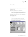
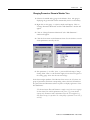
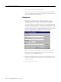
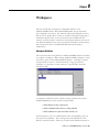
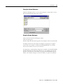
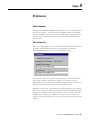
3-2
Monitor View
3. Under the Parameters section of the Monitor View, notice the Trip
Status block is highlighted. The fault will be listed in this area.
(If the Trip Status block is not visible, contact your instructor.)
To show trip status block, right
click on any block and select
Parameter 14 “TRIPSTATUS”
4. Reset the overload trip (press the blue button) and observe the Trip
Status.
5. Now observe the I/O status in the lower right hand quadrant of the
Monitor View. Operate the Hand-Off-Auto switch. Note which input
point (on the E3 overload relay) that the H-O-A switch is connected.
6. Place the HOA switch into HAND mode and press the red push
button. Note which input point (on the E3) that the auxiliary contact of
the 509 NEMA starter is connected.
7. Notice the gauges and trend graphs on the Monitor View. There are
three analog gauges and two trend graphs on the Monitor View for all
devices. When the Monitor View is opened for the first time, factory
default parameters for each gauge and graph are displayed.
What is a Parameter?
All DeviceNet components can store and report data. We refer to the
individual pieces of data as parameters. The data can be divided into three
categories as noted below:
•
Process data - e.g.:
o Amperes on Line 2
o Ground fault Current
o Time until trip occurs
•
Configuration data - e.g.:
o Trip Class
o Motor Full Load Amps (FLA)
o Delay before trip
•
Device specific data - e.g.:
o Firmware revision
o DeviceNet Node address
o Network Baud rate
IntelliCENTER Software will allow the user to change configuration data in
the second group above.
The E3 has more than 70 parameters. For more information, refer to the E3
manual, chapters 5-7 for a complete description of these parameters.
Publication 2100-RM003B-EN-P- March 2003