1
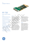
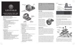
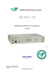
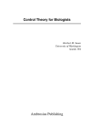
QUAD_Steerer_Manual.doc 26 - July - 2008 User Manual Rev. 1.2 HV QUAD / HV Steerer - Option HV-USB - Option DVM 16 Electronics for Science and Research Kellerweg 23, D - 67582 Mettenheim Germany www.stahl-electronics.com HV QUAD Series Installation and User Manual, Rev 1.0 TABLE OF CONTENTS 1. Safety Hints ………………………………….…………………………………… 3 2. General Information and Overview………………….………………………….. 2.1 Purpose and Description of the Device…………………………….. 2.2 Functional Principle and and Block Diagram………………………. 2.3. Device Variety……………………………………………………… 4 4 4 5 3. Installation ……………………………………………………………………..… 6 3.1. 3.2. Mechanical and Electrical Installation……………………………… Software Installation……………………………………………… .. 3.2.1 USB-Driver…………………………………………………. 3.2.2 LabVIEWTM control program………………………………. 4. Operation and Control Elements ……………………………………………….. 4.1 4.2 4.3 4.4 4.5 4.6 6 6 6 8 10 Elements on the front plate………………………………………… Control Software…………………………………………………… Output Characteristics …………………………………………….. Input and Transfer Characteristics…………………………………. Error Detect Output………………………………………………… Switching the device off …………………………………………… 10 11 13 15 16 16 5. Floating Ground Option…………………………………………………………. 16 6. Maintenance………………………………………….…………………………. 17 7. Specifications……………………………………………………………………. 18 Appendix…………………………………………………………………………… 19 List of commands………………………………………………………….. 19 Declaration of Conformity ………………………………………………………… 21 2 www.stahl-electronics.com phone: +49 6242-504882, fax: +49 6242 504884 HV QUAD Series Installation and User Manual, Rev 1.0 1. Safety Hints Observe all installation, operation, and safety instructions Rear side switch turnes device completely off This equipment must be connected to an earth safety ground Do not modify the unit Do not operate in wet/damp conditions Disconnect power before servicing Do not block chassis ventilation openings Beware of external magnetic fields Operate caryfully with respect to risk of electrical shock Routinely cleaning from dust No outdoor operation Prior to operation, thoroughly review all safety, installation, and operating instructions accompanying this equipment. If the device is not in use for a longer time, it is recommended to turn the mains switch at the rear side off, otherwise the device will not be completely separated from the mains supply. This product is grounded through the grounding conductor of the power cord. To avoid electrical hazard, the grounding conductor must be connected to protective earth ground. Do not make electrical or mechanical modifications to this unit, which are not authorized by the manufacturer. To avoid electric shock hazard, do not operate this product in wet or damp conditions. Protect the device from humidity or direct water contact. To avoid electric shock hazard, disconnect the main power by means of the power switch and power cord prior to any servicing. Slots and openings in the chassis are provided for ventilation purposes to prevent overheating of the equipment and must not be restricted. All 4 case vents should continously be cleared (fan inlet at rear side, air oulet at rear and two at top side), in order to prevent overheating. If mounted in a rack, please allow 2cm clearance at the top cover with respect to the next device above. If in doubt about the sufficiency of air ventilation, provide a software readout of the internal temperature sensor for regular inspection, e.g. every 2 minutes. A temperature over 55°C indicates inadequate air ventilation. Additionally a second sensor can be read out manually in the displays protocol mode (see section 4.1). External magnetic fields can impair, damage or even destroy this device. A maximum external field strength of 10mT is admissible and must never be exceeded. This statement applies for static as well as alternating fields. If in doubt, check possible external field e.g. with a hall probe before switching the device on. In case an external field strength of 10mT is exceeded, once or permanentely, the device may overheat or cause excessive power consumption. This device can produce a voltage up to +/-500VDC at its output lines, which is harmful in case of direct touch with the human body. This voltage may be even exceeded, in case an internal failure occurs. Care must be taken to avoid unintentional touching of any output line by the human body or any devices which might be endangered by high voltages. After long operation, or operation in a dusty environment it is strongly recommended to have the internal parts of the device cleaned by the manufacturer, or an appropriately qualified workshop in order to ensure proper operation and reduce the hazard of overheating. Outdoor operation of the device is not admissible. 3 www.stahl-electronics.com phone: +49 6242-504882, fax: +49 6242 504884 HV QUAD Series Installation and User Manual, Rev 1.0 2. General Information and Overview 2.1 Purpose and Description of the Device Purpose of the HV QUAD/Steerer series devices is the supply of stable DC voltage from 0V to +/275V, optionally up to +/- 450V for electrostatic lenses, especially Quadrupole Lenses, Steerer/Deflector Plates and Ion Traps. Unlike DC power supplies, the outputs currents are limited to small values, and the outputs are optimized for short and long term stability, low ripple, low noise and low temperature drift. Eight input channel are provided, each controls internally two output channels, which are complementary: Every pair of output channels has the same absolute value of voltage, but opposite output polarity. The device is housed in a standard 19-inch rack-mount case. User control of the device can be accomplished by PC control programs, utilizing a standard USB connection (USB 2.0 compatible) in case of the device Option “HV-USB”, or via analog voltage inputs at the rear side. 2.2 Functional Principle and Block Diagram The following picture displays the internal structure, illustrates the functional principle and the typical application. The output voltages are either controlled by analog input voltages, or digital by personal computer (PC) based control. In both cases (analog or digital control) the set-values define the absolute value of a corresponding output amplifier pair. The output DC voltages are calibrated within each pair, in order to match to a high degree, and the voltage sign of the pair-components shows opposite polarity. In total 16 outputs are available, arranged in independend 8 pairs. Regulation circuitry on all 16 output channels establishes individually the desired output DC values. In case a shortcut or overcurrent conditions occurs, the regulation circuitry will fall out of the “lock” state and the corresponding indicator (LED) on the right hand side of the front plate will become red. Without malfunction or overload, the corrsponding indicator will lighten up green again. In case analog control is used, an “Error Detect” output at the devices rear side indicates, if any channel is not locked (low voltage, 0V) or if all channels are correctely locked (high voltage, +5V). Fig. 2.1: Analog or PC control is selectable by the user (dashed line). For clarity only one of 8 independend output channel pairs is shown. The typical application is the supply of electrostatic quadrupole lenses with bipolar voltages. 4 www.stahl-electronics.com phone: +49 6242-504882, fax: +49 6242 504884 HV QUAD Series Installation and User Manual, Rev 1.0 The main difference between the “Quadrupole” and “Steerer” variant lies in the fact, that the output range of the Quadrupole outputs are unipolar (e.g. 0…+450V and 0…-450V for one output pair), but truly bipolar (e.g. -450V… +450V, +450V…-450V) for the Steerer variant outputs. The latter feature a completely continous and glitch-free zero-transitions (no switching around 0 V), which eases its application compared to other devices. From serial number 015008 and higher it is possible to exchange at any later time from “Quadrupole” to “Steerer” variant by exchanging the corresponding output slots (contact manufacturer in that case). 2.3. Device Variety The following devices are currently members of the HV series device family: Output voltage -200V … +200V 8 channels available Output voltage -200V … +200V 16 channels available Output voltage -500V … +500V 8 channels available Output voltage -500V … +500V 16 channels available Output voltage -1kV… 0 or 0…+1kV 4 channels available Output voltage -1kV… 0 or 0…+1kV 8 channels available HV 200-8 HV 200 HV 200-16 HV 500-8 HV 500 HV 500-16 HV 1000-4 HV 1000 HV 1000-8 HV QUAD 275-16 HV QUAD 8 pairs of unipolar complementary outputs with opposite polarity, 0…+/- 275V, or 0…+/-450V designed for electostatic quadrupole lenses HV QUAD 450-16 HV Steerer AMP-HV 500 HV Steerer 250-16 HV Steerer 450-16 8 pairs of bipolar complementary outputs with opposite polarity, designed for electostatic quadrupole lenses and steerer plates similar to HV 500-16, but with analog inputs 5 www.stahl-electronics.com phone: +49 6242-504882, fax: +49 6242 504884 HV QUAD Series Installation and User Manual, Rev 1.0 3. Installation 3.1. Mechanical and Electrical Installation Positioning: Provide sufficient air cooling of the device and loacte in normal horizontal position to allow for defined air convection. Rack mounting into a standard 19” rack is as well possible as resting the device on a table. If mounted in a rack, please allow 2cm clearance at the top cover with respect to the next device above. All 4 case vents must permanently be cleared (fan inlet at rear side, air outlet at rear and top side), in order to prevent overheating. If in doubt about the sufficiency of air ventilation, provide a software readout of the internal temperature sensor for regular inspection, e.g. every 2 minutes. A temperature over 55°C indicates inadequate air ventilation. Alternatively the temperature of a second sensor can be read by switching the display to the protocol mode (see section 4.1, below). Keep air vents always cleared to ensure sufficient ventilation Connecting to mains power: Connect the device to the mains power supply by using an appropriate power cord, being properly wired and providing a grounded outlet. The power cord must be suited with respect to possible load currents and should be rated to 5A current. Cabling of voltage outputs: Always provide appropriate and safe cabling when connecting the device to other devices or vacuum/experimental setups. Cabling is prefered using high voltage cable with proper shielding. SHV connector cables are a suitable choice in order to ensure proper shielding against exernal noise pickup and in order to provide protective ground for safety reasons. Always be aware about the potential hazard of high electrical voltages to human beings and sensitive objects of all kind (see also safety hints in section 1). Please note, that wiring only can be done when the device is turned off, put to zero, or the respective channel is brought to a high impedance state. Connecting a powered-up output to external circuitry can easily cause sparks and electrical discharges. The resulting overvoltages can severely and permanentely damage the device itself and also external circuitry. USB connection, in case of option “HV-USB”: Use a standard type-A-B connnection cable (USB 2.0 standard) to connect the device to the control computer. After connecting to a PC under Windows XP, the “Found New Hardware Wizard” should open (see next section for detailed description), regardless if the HV-Series device is already switched on or not, since the corresponding receiver inside the HV-Series device is powered by the USB bus itself and therefore autonomous. Cable length can be prolongated using an appropriate USB hub or repeater. 3.2. Software installation (Option “HV-USB”) 3.2.1 USB-Driver The HV-Series devices use the USB bus for connecting to a control PC. After proper cabling of the USB connection (see section before) the “Found New Hardware Wizard” under Windows XP should open up. Depending on the Windows XP version allow a few seconds to automatically identify the connected device and install drivers, or follow the described steps below. The automatic or manual 6 www.stahl-electronics.com phone: +49 6242-504882, fax: +49 6242 504884 HV QUAD Series Installation and User Manual, Rev 1.0 installation will install the USB CDM drivers from FTDI Ltd., which is the manufacturer of the USB bus interface circuitry. The supplied installation CD provides suitable drivers for operation under Windows XP. In case FTDI drivers are already installed, a de-installation is recommended before a new re-installation with the latest diver version. Latest drivers, also for different other operating systems (Linux, Mac OS, Windows CE) can be downloaded from http://www.ftdichip.com/FTDrivers.htm. Execute the following steps under Windows XP after automatic start of the “Found New Hardware Wizard”: The following screen opens up, in which you activate the last button “No, not this time” and continue with “Next”. In the following window choose “Install from a list or specific location” => “Next” And afterwards you choose “Search for the best driver in these locations” and “Include this location in the search”. Browse now to the Installation CD and select the appropriate path with the USB drivers. 7 www.stahl-electronics.com phone: +49 6242-504882, fax: +49 6242 504884 HV QUAD Series Installation and User Manual, Rev 1.0 Click “OK” and “Finish” to complete the first driver installation. After a few seconds the first window will show up again (“Found New Hardware Wizard”). This is because the drivers come in two separate parts, which both have to be installed. Go through the installation steps in the same way as before. After completion, the USB drivers are ready for use and Windows indicates this by showing “HV Series: Device Ready” (or similar) in the lower right screen corner for a couple of seconds. Windows usually recommends to restart Windows now, but for immediate use of the HV-Series devices one can skip this point. Nevertheless the PC should be restarted at a later point and latest before installing any other piece of hardware or software. 3.2.2 LabVIEWTM 8.0 control program Assuming that the LabVIEWTM development environment in Version 8.0 or higher is available on the target PC, copy the path containing the LabVIEWTM source code VI’s from the installation CD to a proper place of your choice on a local drive. By double-clicking on the file “HV-ControlPanel.vi” in the path “ui” (“User Interface”) the control panel for HV Series devices will open, which can immediately be started by clicking on the start-arrow in the upper left corner. 8 www.stahl-electronics.com phone: +49 6242-504882, fax: +49 6242 504884 HV QUAD Series Installation and User Manual, Rev 1.0 See section 4.2 for more detailes about operating the control program. In case that the LabVIEWTM development software in version 8.0 or higher is not available on the PC controlling the device, there is a second option. The so-called “LabVIEWTM run time engine” can be installed from the installation CD and the application program (containing the control software for the HV-Series) can be run subsequently. In this case modifications of the control software or implementation in own programs are not possible but the completed software can be run unchanged in the version as it is. Please contact manufacturer for more detailes and possibilities, in case changes of the program are desired. To install, run the LabVIEWTM Runtime Installer Wizard, and follow the instructions. RuntimeEngine File Icon You will be requested to choose an installation directory and location for unzipping the required files. Furthermore (in case not installed before) the National Instruments VISA drivers need to be RuntimeEngine File Icon installed, which enable the LabVIEWTM software access to the PCs hardware resources. After completion of these two installations, the HV-Series control program can be run as executable file. 9 www.stahl-electronics.com phone: +49 6242-504882, fax: +49 6242 504884 HV QUAD Series Installation and User Manual, Rev 1.0 4. Operation and Control Elements 4.1 Elements on the front plate mains supply switch Power-On LED LCD display LED indicators The front plate contains several control elements for the device. The device is powered up after turning on the rear-side mains supply switch and also the power button on the front plate. A warning beeper will temporarily sound, which is used for ventilation fan monitoring. The Power-on-LED (green), indicates proper operation of the internal +24V circuitry. If the device is not in use, it is recommended to use the rear side mains switch to cut it completely off from mains supply. This is recommended in oder to minimize small supply currents which flow, when the the rear side switch is kept on, and also for safety reasons (e.g. overvoltages occasionally occuring on the mains supply line). The LCD display on the front side has several functions. In PC controlled mode (option “HV-USB”) it shows informations about received commands and the latest voltage settings for the output channels. It can be run in two modes: In the “Protocol Mode” all commands, which are received via the USB connection are listed, subsequently one after another. Also the devices internal temperature is shown, regardless if the option remote control option “HV-USB” is used. In the “Voltage Mode” all programmed voltages are listed, sorted by channels. The display modes are toggled by pressing the LCD-display key on the front plate. In case the option “DVM 16” is used, all 16 output voltages on the rear side output lines are internally measured, and displayed at the right hand side of the display at an update rate of roughly 1/sec. Please note, that the indicated voltages are displayed with a much coarser precision than the corresponding output voltages are defined (see also specifications in section 7). The LCD display goes into into power-save mode after roughly 60 min. Any press on the LCD-display key reactivates the backlight again. By toggling to the Protocol Mode the serial number and the number of the virtual COM port, under which the device is accessible from the PC user surface can be seen, as soon as communication with the controlling PC is established. Picture of LCD display in “Voltage Mode” 10 www.stahl-electronics.com phone: +49 6242-504882, fax: +49 6242 504884 HV QUAD Series Installation and User Manual, Rev 1.0 The LED indicators on the right hand side of the device show the overload status of the individual output channels. No light = internal malfunction, channel not operational Green Light = status ok, no overload. Red Light = overload or error condition A LED will become red, when the programmed voltage setting cannot be held correctely at the respective output at the rear side. This can have several reasons. The most common are: 1. 2. 3. 4. There is a problem with the external circuitry, which is attached to the device, maybe a short cut to ground or short cut to another channel or other voltage supply by external cabling. Too much current is drawn from the output, e.g. because of heavy eletrical leakage currents or discharges in vacuum. At heavy capacitive loads (several micro-Farad) the output takes several seconds to built up the desired voltage. The LED therefore might turn red shortly before becoming green again after some seconds as soon as the desired voltage is settled. An internal error appeared. The latter can be excluded, if the LED becomes green again after removing all external cabling. Please note, that in case large voltage steps are programmed (e.g. from minimal voltage to maximum value) the indicator might become red for a short moment, since the output value will not instantaneously coincide with the programmed value. 4.2 Control Software (option “HV-USB”) After starting the LabVIEWTM main VI oder application program the following user surface will appear, which can be operated in a mostly intuitive style. 11 www.stahl-electronics.com phone: +49 6242-504882, fax: +49 6242 504884 HV QUAD Series Installation and User Manual, Rev 1.0 While starting up, the list of connected device (upper left corner) will appear and the program will list all recognized HV-Series devices inside the window. please note, that before taking any action the user should click once to select a device for further operation. picture shows a list with two recognized devices inside the displayed list. The informations about the listed devices show: - device serial number (e.g.: HV016, for a HV-Series device with serial number 016) - the number of available channels on that specific device - the voltage rating (e.g. 500V) - the COM port number, under which the device will be accessible in Microsoft Windows from the PC. Note, that the USB driver on the PC will enumerate detected USB devices automatically. This COM port number may vary from PC to PC and does not depend on the connected HV- Series device itself. If a new device is connected while the program is already running, the list can be forced to be updated by pressing the button. Next right to the list of connected devices the user can set the voltages of each channel in the numerical control field, either manually by entering numbers or by clicking on the up/down arrows. A step size can be defined in the control field underneath the voltage controls. The button “On/High Impedance” selects, if a channel is used and activated, or de-activated and set to zero volts. Note, that this option is on purpose excluded in devices with serial numbers 014001, 015008, 015009, 015010. At right hand side besides the numerical control field for the voltages, the “Overload Status Indicators” appear. They are similar to the LEDs on the front plate and indicate the status of the regulation circuitry for every channel. As long as the set voltage can be held, the indicator is green otherwise red. Routinely once per second the control program reads the actual status over the USB bus and updates the indicator colour. Nevertheless the standard preselected update rate of onc request per second could be slowed down by considerable CPU load or competing LabVIEWTM processes, working in parallel. A forced and immedeate status check is therefore provided, if the user clicks on the button. After presseing the Options Button , the user can manually read the device internal temperature in the subsequent window or enter manually commands to the HV- Series device (for advanced users, see also the list of commands in the appendix). 12 www.stahl-electronics.com phone: +49 6242-504882, fax: +49 6242 504884 HV QUAD Series Installation and User Manual, Rev 1.0 4.3 Output Characteristics General properties The HV series devices feature stable bipolar low-current DC voltage outputs. The 16 outputs are grouped in 8 pairs of complementary channels. Every output pair has two components: A “positive” output and a “negative” output, both are unipolar in case of the Quadrupole version, bipolar in the Steerer version. These pairs are labelled as 1+ and 1- up to 8+ and 8-. All “positive” outputs range from 0V to the maximum specified output voltage; which is either 275V or 450V unipolar, or bipolar +/-450V in case of the Steerer version. An important feature is the glitch-free, continous zero transition of the outputs, if the voltage is swept through zero. The same applies for the corresponding “negative” outputs, which differ from the “positive” ones only by their sign of voltage. The 8 pairs of output lines are available on 16 BNC output connectors at the rear side of the device Apart from opposite sign, the two components of all output pairs are designed to match well to each other with respect to their absolute voltage. The remaining mismatch is typically better 0.02% at voltages above +/-125V. (For further detailes please refer to the specifications in chapter 7.) Output channel scheme, showing one of eight output channel pairs, which deliver DC output voltages at opposite sign (complementary positive/negative outputs) but with same absolute value The output channels can deliver currents up to the internally limited values. The purpose of the limitation is mainly to restrict currents to an amount, which is minor harmful to external devices or human beings. By factory a minimum guaranteed supplied current of +/-50µA is set, the maximum value is limited by the safety circuitry to less than +/-80µA at full output voltage (Quadrupole version), or less than +/- 200µA (Steerer version respectively). Before using an output channel, the user should ensure the completion of external cabling as long as the channel is put to zero volts or the device is completely switched off. It is not recommended to plug a high voltage cable, if the high voltage is already present: In case larger capacitive loads exists or an unintentional short cut to ground or to any other voltage occurs, high transient electrical currents or gas discharges in air may damage the HV device severely or eventually other externally connected devices or experimental setups. Always finish cabling before turning the respective output channel on. 13 www.stahl-electronics.com phone: +49 6242-504882, fax: +49 6242 504884 HV QUAD Series Installation and User Manual, Rev 1.0 The admissible cable length (standard BNC cables RG58) is 200m. Longer cables are possible, but their capacitive load on the outputs has to be considered (see remark below under “settling time”). Using very long cables of 1 km or more is not recommended because of possible excessive noise pickup and sensitivity to capture 50 or 60 Hz hum, either capacitively or inductively. Resolution If controlled by the USB bus, the outputs feature a stable setting of voltages with typically 15 milliVolts resolution, corresponding to an internal resolution of 16 Bits, or few milliVolts offset and less than 0.1% scaling error in case the analog input is used (see specifications in chapter 7 for more detailes). Every output is equipped with a correction loop, which ensures low voltage fluctuations and very good short term stability in order of a few ppm only (with respect to output span). Settling time The outputs voltage settling time depends on the external load and is generally limited by the maximum internal voltage slope of roughly 2500V/sec. In high accuracy applications allow up to 5s to settle the outmost 100ppm accuracy. For small voltage step sizes ( 10V) the settling time to reach 0,1% accuracy is less than 1s typically. Nevertheless factory settings can be adapted to achieve faster response time, or in contrast, longer response time and greater stability on heavy capacitive loads, like very long output cables. The figure of “settling time” of any high-voltage amplifier always represents a trade-off between current-driving load capability, precision and maximum (capacitve or resitive) load. Eventually contact manufacturer for optimization of the settling time characteristics of an individual device in order to suit it to a certain external setup. Output accuracy, fluctuations and loads Precision components ensure a very good basic accuracy and very low long-term drift, both on a 10-4 level. A PID regulation loop on every individual output ensures remarkable stability and compensates for short term temperature-depending or semiconductor-inherent fluctuations. Intrinsic short term stability is therefore on the level of Millivolts, corresponding to only a few ppm’s (part per million) with respect to the full voltage span. For detailes about 24h-fluctuations see technical data in section 7. All outputs feature protection resistors of 2.7 kOhms serially to the internal output amplifiers, which will cause a voltage drop as soon as current is drawn from any output. Please take into account that voltage drop (according to Ohms law) for operation with considerable load currents or for high precision measurements. Note, that also Digital Multimeters draw a considerable current. E.g. 250V / 10MOhms = 25µA is drawn from a multimeter with 10 MOhm input resistance. Loading the outputs with considerable currents should be avoided, if best possible precision and stability is required, since the device is rather optimized for low current applications like electrostatical lenses than driving current loads. Short cuts or other heavy loads at the outputs Generally all outputs are short-cut proof, with respect to GND-short cuts or short cuts to any voltage between the specified min./max. voltage. Nevertheless suddenly occuring short cuts or overvoltages, for instance caused by sparks or other discharges represent a considerable hazard. Even though the outputs feature an internal protection circuitry (based on the output resistor, melting fuse, inductive blocking and overvoltage drain), care should be taken to avoid any possibility to create overvoltages or heavy output current loads, in order to ensure a long life time. Also intentional short cuts at the 14 www.stahl-electronics.com phone: +49 6242-504882, fax: +49 6242 504884 HV QUAD Series Installation and User Manual, Rev 1.0 outputs, e.g. caused by high voltage semiconductor switches are not admissible. In case a fast switch is placed at the output for switching purposes, a series resistance in the order of 2.5kOhm at the respective output is recommended. Recovery from Overload If a overload conditions occurs (indicated by red LED light on the front plate), the outputs show a hysteresis behaviour, which means that the load has to be diminished to a certain amount below the overload threshold, or completely removed. This hysteresis is typically 10% of threshold current or a few volts with respect to voltage. Allow the output overload detection circuitry several seconds to pass before indicating green light after the overload condition was removed. 4.4 Input and Transfer Characteristics (analog inputs) In case electrical analog control input lines are used, they will control the output voltages in the sense of linear DC-amplification. For this purpose a male 25pole Sub-D connector is provided at the rear side of the device with eight DC-voltage input lines with a nominal range of 0V…+2.75V, or 0V … +4.50V respectively, which are buffered by high impedance input amplifiers. Position of 25pole analog I/O connector at rear side Pinout of 25pole Sub-D connector The metal collar should be used for shielding purposes, whereas the Ref-GND Pin represents the reference mass for the analog input and outputs. These input voltages are subsequently amplified by precision high voltage amplifiers by a factor of 100, or -100 for the positive or negative outputs respectively. The two components of all output voltage pairs match well to each other with respect to their absolute voltage. The remaining mismatch is typically better 0.02% at voltages above +/-125V, typically 0.01% at a voltage of +/-250V. 15 www.stahl-electronics.com phone: +49 6242-504882, fax: +49 6242 504884 HV QUAD Series Installation and User Manual, Rev 1.0 The analog input lines are overvoltage protected (max. +/-20VDC permanentely, or 1.5kV ESD human body model) and refer to a common reference GND (Pin 13 at the 25pole connector). Even though this reference Pin has galvanical connection to the metal shield GND of the housing, one should use this dedicated 0V-reference Pin (Pin 13) as reference for input and output lines, and rather use the case ground for shielding purposes only. Response time of the output with respect to changes at the inputs are rather determined by the HV output stages (see above “settling time”). The HV-Series devices are primarily not designed for amplification of AC signals; their frequency response is therefore intentionally kept low with a cutoff frequency (level dependend) of a few Hz. Output verification lines Pins 1…8 and 14…21 of the 25 pole connector provide verification lines for remote checking of correct output operation. These analog outputs provide the down-scaled output voltages, i.e. a factor of 100 smaller than at the rear BNC outputs. Pins 14…21 account for the “positive” outputs, Pins 1 to 8 for the “negative” ones. Their voltages are also displayed on the front side LCD-display, in case the option “DVM 16” is installed. 4.5 Error Detect Output There is one more BNC output at the rear side, besides the HV-outputs: The “Error Detect” output provides a TTL/CMOS compatible line, showing a “low” level in case ANY output channel has a overload/error condition. Otherwise the output shows a “high” level of ca. +5V. 4.6 Switching the device off After switching the device off (from mains supply) the output voltages will assume ground potential. Let at least 2 minutes pass, in order to allow all voltages to fade, before changing the cabling or touching any bare output line by hand. It is recommended to use the rear side mains switch, in order to completely separate the device from external mains supply. 5. 5. Using the Floating Ground Option Floating Ground Option - currently under development for HV-Quad /HV-Steerer - 16 www.stahl-electronics.com phone: +49 6242-504882, fax: +49 6242 504884 HV QUAD Series Installation and User Manual, Rev 1.0 6. Maintenance The HV Series Voltage Source is designed for years of reliable operation. Under normal operating conditions, it should not require electrical maintenance, but routinely cleaning of dust, and in longer time intervals, replacement of rear fan (see below). If any further question should arise, please contact the manufacturer. Routine cleaning All ventilation openings – top, bottom, sides, and rear panel – should be checked periodically and kept free of dust and other obstructions. A vacuum cleaner may be used to clean these vents when the unit is powered off. Do not use compressed air to clear the vents. The front panel may be cleaned periodically with a clean cloth and alcohol solution, when the unit is powered off. It is recommended to send the device to the manufacturer routinely in 2-year intervals for internal cleaning from dust. Visual inspection of the degree of internal pollution and accumulated dirt is possible, but should be carried out by qulified personnel only. In this case wait at least 5min after switching power off, and disconnecting all external high voltage lines and the mains cable. After removing the 6 screws of the upper lid, the latter is removable and allows a look on the internal electronics boards. Very careful cleaning by qualified personnel and using a small miniature vacuum cleaner is admissible. Before continuing operation, ensure that the lid is placed correctely (orientation with respect to rearside/frontside) and that all 6 lid screws are placed and tighened again. In any doubt of possible internal damage contact manufacturer before continuing any further operation. Calibration Under normal operating conditions, the HV Series Voltage Source will not require regular calibration. However, it can be returned to factory for complete electrical and mechanical inspection and calibration purposes. Also, if required, an certificate can be issued for traceability. Contact manufacturer for additional information. Fan life time and temperature monitoring The ventilation fan at the rear side of the housing is a part which shows deterioration in time. Exchange of this part is recommended after latest 50.000 hours of operation. Please contact manufacturer for replacement after long term operation. Complete failure might lead to overheating of the device. Several temperature fuses and other protection measures ensure safety against fire hazard in this case. Nevertheless, it is strongly recommended to read out regulary the devices temperature by software means in order to monitor the devices internal temperature and therefore to ensure avoidance of damage to the device. In the “protocol mode” of the front display the user can also visually check the internal temperature. Values above 65 degrees Celsius are not admissible, values above 55 degree Celsius indicate a possible problem. A warning sounder (beeper) will activate in case of low fan rotational speed (applies for versions from manufacturing date 12/2010 and later). Fire hazard Please note, that excessive accumulation of dust inside the case of the device can lead to overheating. This, together with possible discharges increases the risk of fire, caused by electrical sparks. Routinely cleaning the device from dust minimizes this risk. It is therefore recommended to send the device to the manufacturer routinely in 2-year intervals for internal cleaning from dust, or to have it cleaned by an accordingly qualified electronical workshop. Ambient air, containing oil mists (e.g. proximity to a vacuum forepump or mechanical machines) places a severe danger, since enflammable substances could enter the device through the ventilation holes and cause fire. If in doubt, regular cleaning by a qualified electronical workshop or the manufacturer is strongly recommended. 17 www.stahl-electronics.com phone: +49 6242-504882, fax: +49 6242 504884 HV QUAD Series Installation and User Manual, Rev 1.0 7. Specifications Parameter Output Voltage Range HV Quad 275 HV Quad 450 Output Connectors Per output Current Per device Output Reference Ground Remote Control via USB (option “HV-USB”) Remote Control via analog voltages Accuracy: % of Setting, Related to full span Offset error Ripple Noise, 0…10kHz unipolar 0…-275 V and 0… +275 V (up to 250 V nominal range, above: overrange) unipolar 0…-450 V and 0… +450 V (up to 425 V nominal range, above: overrange) BNC 50 µA guaranteed max. ±400 µA All outputs share a common GND, which is identical to the shield of the BNC connectors USB 2.0 compatible connection to PCs. Galvanic isolation is provided. Free LabVIEW TM 8.0 based user surface and driver routines. 25pole Sub-D connector provides analog input lines, which are scaled up by a factor of 100, or -100 Reference ground is not galvanically isolated from case ground. typical 0.015% USB control maximum 0.05% typical drift 0.002% per day ±100mV ±10mV per day ±10mV 5mVrms 1.5Vrms Optional Analog Control (25pole connector) Input voltage range Nominal Overrange 0 … 2.5V, 0…4.25V 0 … 2.75V, 0…4.5V typical maximum DC Amplification factor 100, -100 Accuracy: (inputs within nominal range) Scale error 0.02% 0.1% Offset error, output related +/-25mV +/-150mV Mismatch between positive and negative output voltage 0,019% @ 125V 0,05% @ 125V for one output pair 0,010% @ 250V 0,03% @ 250V Channel-Channel crosstalk 66 dB Ripple 5 mVrms Noise, 0…10kHz 2.2 mVrms Output verification lines Accuracy: Scale error 0.02% 0.05% Offset error 1mV 275V Version / 450V Version 275V Version / 450V Version typical drift 0.004% per day ±12mV per day Front Plate LCD Screen, Digital Voltmeters Accuracy: Scale error Offset error Storage Temperature Magnetic Field Operating Humidity & Temperature AC Power Supply Case dimensions Weight typical 0.04% 0.1V maximum 0.1% 0.5V -55C° to +105C°. max. 10 mT admissible noncondensing humidity, temperatures between +10°C and +40°C AC input power 230VAC at 50Hz. The power entry module is EMI/RFI-filtered. Fuse: medium fast blow 2.5A. Typical Power Consumption: 60W 19.00” wide x 10” deep. Front-panel mounting holes are configured for M6 rack configurations approximately 4.9kg, configuration dependent 18 www.stahl-electronics.com phone: +49 6242-504882, fax: +49 6242 504884 HV QUAD Series Installation and User Manual, Rev 1.0 Appendix List and Description of communication commands The following commands are sent/received in order to communicate between the HV Series voltage source and a control device, like a standard PC. The commands are sent in clear ASCII text strings over a standard USB-connection (1.0 protocol, but also 2.0 compatible). In case LabVIEWTM (Version 8.0 or higher) is used, a complete driver program with open source SubVI’s is provided by the manufacturer. Self-written programs or other commercial software can use the command structure described in the following section as well. Establishing connection and sending commands: Before sending any command, the USB connection to the device has to be established. This is done by installing an appropriate USB driver. Drivers for Windows (2000, ME, XP, Vista), Mac OS and Linux are provided. Please contact manufacturer or see the USB-manufacturers homepage (www.ftdichip.com) for latest updates. The following table lists the available commands. The abbreviation “DDDDD” stands for the name of the device including its serial number, e.g. “HV009” means HV device with serial number “009”. All commands must be terminated with an ENTER (13 in ASCII code). After establishing the USB link to the HV device and turning it on, the IDN identifier should be sent in order to retrieve the serial number, since it will be used to adress the device. Subsequently the devices voltages can be set, according to the table below. Please see also examples and more detailes after the table. Command String to be sent to device Received from device Observations Identify IDN HV001… The device replies with its name and serial number Set voltage DDDDD CHXX Y.YYYYY CHXX Y.YYYYY Read temperature Check lock status of all channels DDDD TEMP XX.XºC XX is the channel number (01 up to 16) Y.YYYYY is a decimal number between 0 and 1 which represents the scaled voltage. “0” represents the minimum voltage (e.g. -500V), “1” the maximum value (e.g. +500V). 5 digits after the comma have to be provided. XX.X is the temperature in ºC DDDDD LOCK B3 B2 B1 B0 Turn On/Off individual outputs DDDDD SWITCH B3 B2 B1 B0 Send string to LCDdisplay DDDDD DIS “string” Set correction parameters DDDDD CORR ………….. Probes all channels to see if any is unlocked. The response is coded into 4 bytes (B3 to B0), see also appendix 3. If a Bit is zero, then locking is ok, if = 1 then a problem occurred in the respective channel Turns certain channels on or to zero. Coding see below, “1” means on, “0” means off Note, that this command is NOT used in the Steerer/Quadrupole Versions of HV-Series devices. Sends a “string” (arbitrary chain of characters, max. 16 characters long) to be displayed on the front LCD display. The string will be visibe in the protocol mode. For format see appendix 2 Change of correction parameter, in a dedicated LabVIEW control, or coded as shown below. For adjustment during manufacturing process only. 19 www.stahl-electronics.com phone: +49 6242-504882, fax: +49 6242 504884 HV QUAD Series Installation and User Manual, Rev 1.0 Definition of device identifiers, sent back from a device upon request by the “IDN” command: The identifier string consists of several parts, returning informations about the device. Every part is separated from the next by a normal “space”-character: Example: “HV023 500 16 b” = “HV” + “003” + “ 500” + “ 16” + “ b” That means: a HV-series device answers, serial number is 023, voltage range 500V, 16 channels, and having bipolar outputs This identifier string is programmed into the FlashRom of every HV-series device by factory. The different string options are: first string part: always “HV” 2nd part: serial number between “001” and “999” 3rd part: voltage in volts, can be any (integer) number between 1 and 100000 4th part: number of channels, presently either “4” or “8” or “16” 5th part: “b” like bipolar or “u” like unipolar “q” like quadrupole lens supply, “s” like steerer supply Command Example for setting a voltage: The command “HV014 CH02 0.00000” puts channel number 2 on minimum voltage, i.e. 500V for a HV500 device (assuming the the devices serial number is 014). The command “HV014 CH02 1.00000” puts channel number 2 on maximum voltage, i.e. +500V for a HV500 device. The command “HV014 CH02 0.50000” puts channel number 2 on half span between minimum and maximum, which is zero voltage. All other voltages between “0.00000” and “1.00000” are scaled linearly, e.g. “0.75000” represents 75% of full span above minimum voltage, which is +250V for a HV500 device. Coding of the 16 channels/bits into the control 4 bytes B 3B2B1B0: The following encoding is used for the “Check Lock” and “Channel on/Off” command. The first 4 bits (= upper nibble) of every Byte is always 0001 = 16dec. This is in order to avoid certain bit-combinations, which could cause trouble to USB/RS232-based communication (like “enter”, “escape”). Next 4 bits (=lower nibble): in B3: in B2: in B1: in B0: ch16 ch12 ch08 ch04 ch15 ch11 ch07 ch03 ch14 ch10 ch06 ch02 ch13 ch09 ch05 ch01 For instance B0 = 0001 0011 means, channels 3 and 4 are off, 1 and 2 are on, in case of the switching command, and with respect to the lock-status it would mean that 3 and 4 are ok, 1 and 2 not locked. Correction Command (advanced users only) The correction command is only used within the manufacturing process and adjusts some correction routines inside the HV series devices. The format of the correction command looks like “HV004 CORR02 0.12345 +0.54321”, which means that the HV-series device with serial number 004 is changed, specially channel number 2 in this case. The span correction comes first (0.12345), then the offset correction (+0.54321). These both numbers represent the correction parameters. The span correction ranges from 0.00000 to 1.99999 (always 5 digits after the decimal point), and the offset correction ranges from -0.49999 up to +0.49999. For the offset the sign “-” or ”+” always has to be sent es well. The decimal point always must be a point and not a comma (“.” and not ”,”). 20 www.stahl-electronics.com phone: +49 6242-504882, fax: +49 6242 504884 HV QUAD Series Installation and User Manual, Rev 1.0 DECLARATION OF CONFORMITY Manufacturer's Name: Dr. Stefan Stahl - Electronics for Science and Research - Manufacturer's Address: Kellerweg 23 67582 Mettenheim Germany. Declares, that the product Product Name: Model Number: HV series voltage supply HV Quad 275-16, HV Quad 400-16, HV Steerer 500-16, HV Steerer 450-16, HV Steerer 250-16 Product Options: This declaration covers all options of the above product(s) Conforms with the following European Directives: The product herewith complies with the requirements of the: 1. Low Voltage Directive 73/73EEC; 2. EMC Directive 89/336/EEC (including 93/68/EEC) and carries the CE Marking accordingly Date Of Issue __________________ 21. June 2008 General Director 21 www.stahl-electronics.com phone: +49 6242-504882, fax: +49 6242 504884